Article

Large Swing Behavior of Overhead Transmission Lines under Rain-Load Conditions

1
School of Energy Power and Mechanical Engineering, North China Electric Power University, Beijing 102206, China
2
Key Laboratory of Condition Monitoring and Control for Power Plant Equipment Ministry of Education, North China Electric Power University, Beijing 102206, China
*
Author to whom correspondence should be addressed.
Energies 2018, 11(5), 1092; https://doi.org/10.3390/en11051092
Submission received: 11 April 2018 / Revised: 25 April 2018 / Accepted: 25 April 2018 / Published: 28 April 2018
(This article belongs to the Section F: Electrical Engineering)

Abstract

:
In recent years, flashover accidents caused by large swings of overhead conductors that frequently occurred under rain-wind condition, greatly jeopardized the normal operation of power transmission systems. However, the large swing mechanism of overhead conductor under the simultaneous occurrence of rain and wind is not clear yet. Thus, a unified model is proposed with derived stability criterion to analyze the large swing of the overhead conductor. The analytical model is solved by finite element method with the aerodynamic coefficients obtained from simulated rain-wind tests, taking into account the effect of wind velocities, upper rivulet motion, rainfall rates, and rain loads on the large swings of overhead transmission lines. The results show that the proposed model can capture main features of the large swing of overhead conductor, this swing being probably due to the upper rivulet’s motion, by which negative aerodynamic damping occurs at a certain range of wind velocity (10 m/s). Furthermore, the peak swing amplitude of the overhead conductors under rain-wind condition is larger than that under wind only, and the rain loads cannot be neglected.

1. Introduction

Under normal operating conditions, the effect of swing of overhead transmission lines subjected to wind is low. However, under the simultaneous occurrences of wind and rainfall, an unanticipated large swing on the overhead transmission lines takes place in China [1,2]. Such large swings of the overhead conductors can reduce the air gap of conductor-to-tower, and cause flashover accidents within a surprisingly short period. Many studies have been carried out to try to unveil the reasons behind this type of large swing and to find the measures to mitigate such vibrations.
Under rain and moderate winds, single or bundled aerial conductors vibrating severely along changing paths with its own major axis, at one time horizontally and at another time vertically, were first observed on Magdalen Islands test lines in Hydro-Quebec, Canada [3]. This type of vibration, namely rain vibration, often exceeded the commonly accepted safe level of amplitude. Hardy et al. [4] further conducted field investigations on either damping or non-damping articulated spacers with regard to rain vibrations. The results showed that the rain vibration frequency within the range of 6~20 Hz was not significantly correlated with wind velocity. Tsujimotio et al. [5] carried out field measurement of the test line with a span of 353 m in length, equipped with 8-bundled aluminum-steel reinforced conductor, as well as theoretical analysis of spring-mass simulation model, to calculate the possible interphase spacing subjected to wind. The results show that the interphase spacing in a long span will be greatly affected by wind turbulence. Clapp [6] calculated horizontal displacement of conductors under wind loading toward buildings or other supporting structures. These calculated results indicated the horizontal displacement relative to the final unloaded sag was not as great as the tangent of the swing angle. Hu et al. [2,7] carried out a series of experimental tests on 1:1 ratio scale conductor-to-tower structure of air gap with different rainfall intensity, wind velocity, and wind directions. The result indicated that wind-blown rain affected the power frequency discharge characteristics of air gap, and obviously reduced the discharge voltage. Jiang et al. [8,9] carried out a series of simulated rainfall experimental tests, by which the effect of rainfall intensity, rainwater resistivity, and air temperature on AC discharge voltage of rod–plane (rod–rod) air gap were discussed. The results showed that rainfall intensity had obvious effect on AC discharge of rod–plane air gap, and there was a significant negative correlation between discharge voltage and rain intensity. Yan et al. [10] presented a numerical model of overhead transmission line section exposed to stochastic wind field to calculate dynamic swing of suspension insulator. The result showed that the numerically determined dynamic swing angles of the suspension insulator were larger than those calculated with the formulas proposed in the technical code, and the dynamic wind load factor was suggested to be in the range of 1.4–1.5, and the statistical peak factor was set to be 2.2. Xiong et al. [11] proposed an online early warning method for windage yaw discharge of GJ type strain tower with rainfall, and the influence coefficient of rainfall was introduced to revise the permissible minimum clearance. Mazur et al. [12] proposed using wireless sensor networks as a technology to achieve energy efficient, reliable, and low-cost remote monitoring of transmission grids. Wydra et al. [13] proposed a method of measuring the power line wire sag by optical sensors, and applied the method of measuring on real aluminum-conducting steel-reinforced wire. Geng et al. [14] carried out a simulated rainfall experimental test to study the effect of rain intensities and paths on power frequency flashover of air gap on a 1:1 ratio scale of conductor-to-tower structure of air gap. The results indicated that the paths of rainwater had some influence on power frequency flashover of air gap, and the flashover voltage to reduce, by 16%, at an air gap of 1.2 m. Zhu et al. [15,16] studied asynchronous swaying of compact overhead transmission line with nonlinear finite method, and proposed the corresponding prevention measures and configuration of interphase spacers. Zhang et al. [17] carried out wind tunnel tests to simulate windage yaw flashover and tower failures on four types of col model, with different hill slopes and valley widths. The results showed that the degrees of wind velocity were increased at valley axis and hill peak, reaching 33% and 53%, respectively, and higher than the 10% stipulated in regulations, tend to cause more windage yaw flashover or tower failures.
Compared with the field measurements and experimental tests on the large swing of overhead transmission lines, theoretical studies related to aerodynamic characteristics are still very limited. Holmes [18] presented a closed-form solution to estimate the along-wind dynamic response of freestanding lattice towers, and derived the expression for the ratio of the aerodynamic damping coefficients to the critical values. The results showed that the windage yaw of the conductor was larger than that of the lattice towers, and as a result, the aerodynamic damping effect of the conductor was obvious, and cannot be ignored. Lou et al. [19] established a nonlinear dynamic transmission line model consisting of three-span electrical conductors to investigate the impact of aerodynamic damping on the windage yaw of the transmission line. It shows that the aerodynamic damping can reduce the maximum value of the windage yaw significantly, but have no obvious effect on its average values. Stengel et al. [20] presented a finite element model of an overhead transmission line using so-called cable elements, and aerodynamic damping was considered in equation of motion by taking into account the relative velocity between wind flow and the motion of conductors. The numerical result indicated that the effect of aerodynamic damping which must not be neglected while dealing with structures of relatively low structural damping in comparison to aerodynamic damping. Zhou et al. [21] established a two-dimensional model to investigate the effect of wind velocity, damping ratio, and electric field strength on aerodynamic stability of the conductor. The results indicated that the enlarged upper rivulet with electric field may be the main cause of aerodynamic instability.
Although many achievements have been made until now, the large swing mechanism of overhead conductor under rain-wind condition is not clear yet. Raindrops hitting the conductor may form rivulets on surface of the overhead conductor. The position of the rivulets is not fixed, but varies with time, and the aerodynamic coefficients additionally depend on time. Furthermore, rainfall has an obvious effect on the air gap of conductor-to-tower, and raindrop impinging force cannot be neglected; therefore, traditional calculation methods for windage yaw are no longer appropriate. In this paper, a unified model with derived stability criterion is proposed to analyze the large swing mechanism. The analytical model is solved by finite element method with the aerodynamic coefficients obtained from simulated rain-wind tests, taking into account the effect of wind velocity, upper rivulet motion, rainfall rate, and rain load on the large swing of overhead transmission lines.

2. Analytical Model of Large Swing of Overhead Transmission Line Induced by Rain-Wind

Overhead transmission tower-line structures consist of towers, conductors, and insulators. A schematic representation of a one-span tower-line structure section is depicted in Figure 1. The conductor is hung with suspension insulator strings between the suspension tower. The inclination of the conductor is α , the span is L , the sag is s , and a segment of the overhead conductor is Δ l .
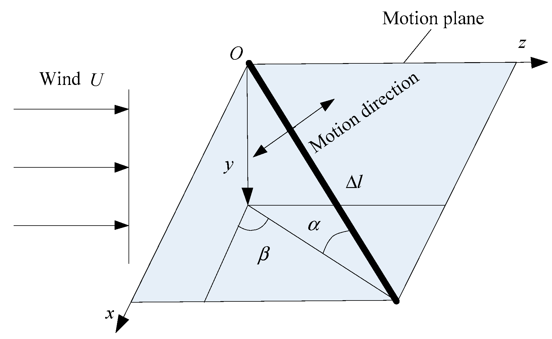
Let us use a rigid and uniform inclined cylinder to represent an overhead conductor segment of Δ l (see Figure 2). The wind angle of the wind towards the cylinder is β , U is mean wind velocity, and the cylinder is supported by springs at its ends. The consideration of such a cylinder, rather than a real conductor, is because many researchers have used it in wind tunnel tests, and some experimental results will be used to verify the analytical model in the present study. Furthermore, a hot summer or high load definitely has an effect on the conductor sag, and the increasing of the conductor length which affected the inclination angle of α. To simplify the analysis, in this section, we assumed the sag is invariable, and the effect of temperature is not taken into consideration.
The mean wind velocity U varies with altitudes and can be obtained by the exponential wind profile expression as
U = U 10 ( y / 10 ) ε
where U 10 is basic wind velocity representing the mean wind velocity during 10 min at the altitude of 10 m, and y is the altitude. ε , the ground roughness coefficient for an open terrain, is 0.16, and for some specific open terrains, is 0.14 [22].
To simulate the stochastic wind field for the overhead conductor, the height above ground is taken into account, and Kaimal spectrum is used to express the variation of wind velocity fluctuation. The Kaimal spectrum is expressed as [22]
U = 0.35 U / ln ( y / y 0 )
where y 0 is the roughens length.
S ( y , f ) = 200 f U 2 / f ( 1 + 50 f ) 5 / 3
where f is frequency, and f = f y / U .
As a preliminary theoretical study, to simplify the analysis, some appropriate assumptions are adopted as follows:
(1)
The rainfall is sufficient to take the form of rivulets on the cylinder with wind. Quasi-steady assumption will be applied.
(2)
The lower rivulet is assumed to add little effect on the aerodynamic coefficients of the cylinder, thus, only the upper rivulet will be considered.
(3)
The cylinder and upper rivulet are distributed uniformly along the longitudinal axis. Axial vortexes and axial flow along the cylinder will not be taken into account.
(4)
Only the swing of the cylinder in along-wind direction will be discussed, whereas in-plane vibration of the cylinder normal to wind direction is not considered.
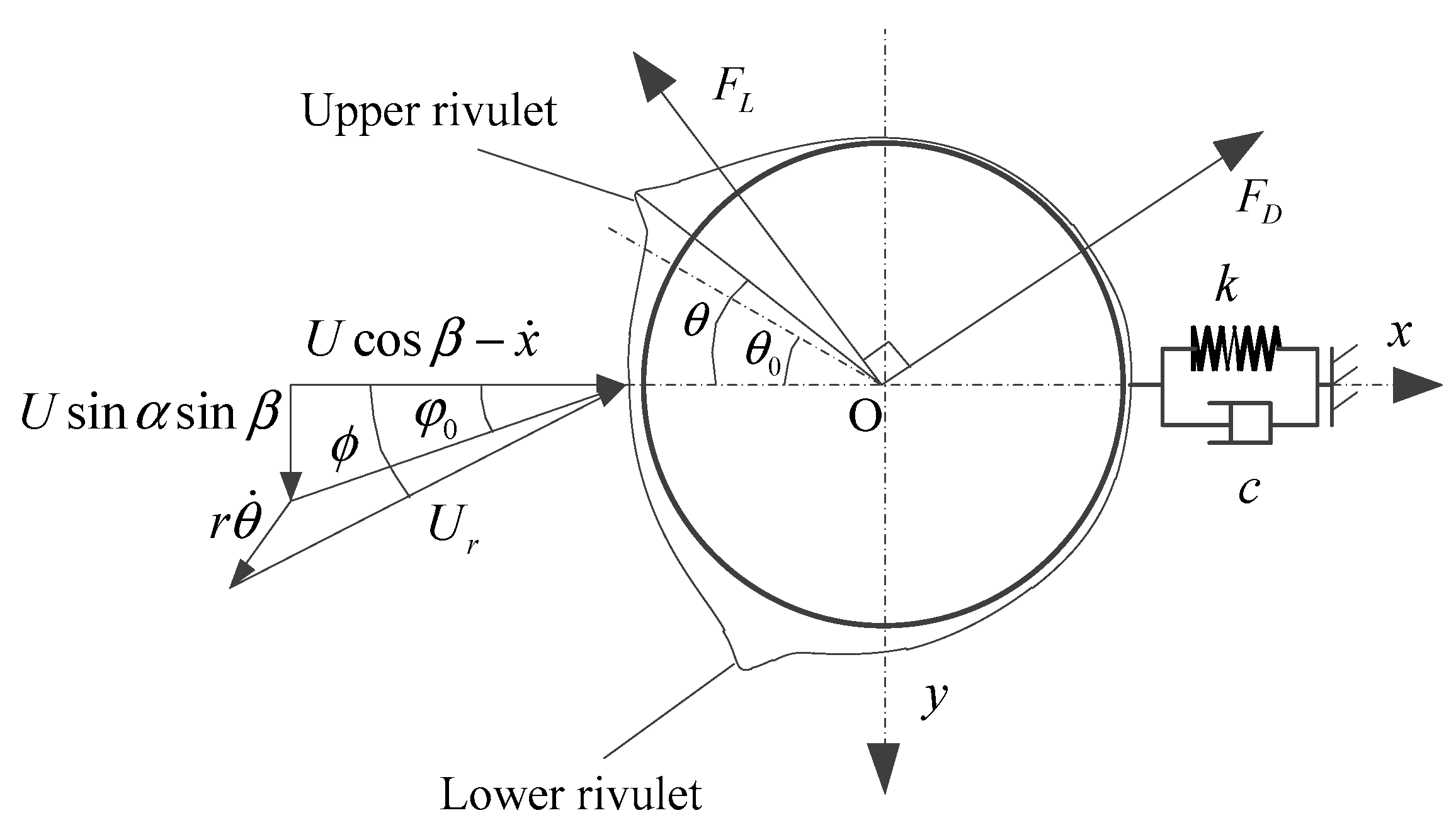
Under a certain rain-wind condition, upper rivulet occurs at the surface of the cylinder. The balance angle of the upper rivulet is θ 0 , by the coupled actions of gravity force, surface tension, and rain-wind loads. The unstable angle of the upper rivulet θ oscillates around θ 0 . The component of the wind velocity U 0 , perpendicular to the cylinder, can be expressed as
U 0 = U cos 2 β + sin 2 β sin 2 α .
The initial attack angle is defined as φ 0 (see Figure 3)
φ 0 = arcsin ( sin α sin β / cos 2 β + sin 2 β sin 2 α ) .
Based on the assumptions given above, the equation of large swing for cylinder takes the following form:
m x ¨ + c x ˙ + k x = F ( λ , ϕ ) ,
where m is the mass of the cylinder per unit length; c is the structural damping of the cylinder; k is the structural stiffness of the cylinder; x is the horizontal displacement of the cylinder; and the term F ( λ , ϕ ) in Equation (6) is the along-wind direction aerodynamic force per unit length of the cylinder and relative attack angle λ = θ + ϕ .
The along-wind direction aerodynamic force per unit length of the cylinder F ( λ , ϕ ) can be obtained by the following:
F ( λ , ϕ ) = ρ U 0 2 r C F ( λ , ϕ ) ,
where C F ( λ , ϕ ) is the aerodynamic force coefficient, ρ is the air density, and r is the radius of the cylinder.
The aerodynamic force coefficient, C F ( λ , ϕ ) , in Equation (7) can be rewritten as
C F ( λ , ϕ ) = = U r 2 ( C D ( λ ) cos ϕ C L ( λ ) sin ϕ ) / U 0 2
where C D , C L are the aerodynamic drag and lift force coefficients, respectively. U r is the instantaneous relative wind velocity.
The instantaneous relative wind velocity and its angle to the horizontal axis are given by
{ U r = [ U 0 sin φ 0 + r θ ˙ cos θ ] 2 + [ U 0 cos φ 0 + r θ ˙ sin θ x ˙ ] 2 ϕ = arctan { ( U 0 sin φ 0 + r θ ˙ cos θ ) / ( U 0 cos φ 0 + r θ ˙ sin θ x ˙ ) } ,
where x ˙ is the horizontal velocity of the cylinder.
A large number of observations show that the raindrop size in horizontal plane obeys a negative exponential distribution [23], which can be expressed by the Marshall–Palmer exponential size distribution as
n ( η ) = n 0 exp ( Λ η ) ,
where n 0 = 8 × 10 3   ( m 3 mm ) for any rainfall intensity and Λ = 4.1 I 0.21 is the slope factor, and I is the rainfall intensity.
Rainfall intensity I was figured out, based 24 h, 6 h, 1 h or 1 min evaluation data received from Meteorological Agency. Some sample values of rainfall [14], as shown in Table 1.
The velocity of raindrop becomes zero very quickly when the raindrop impinges on the high-voltage conductor, which obeys Newton’s second law, as follows:
0 τ f ( t ) + U 0 σ d δ = 0 ,
where τ = η / U is the time interval of impinging, and η is the raindrop radius; σ = 4 π η 3 ρ w / 3 is the mass of a single raindrop, and ρ w is the water density.
The impact force of a single raindrop on a high-voltage conductor can be calculated as
χ ( τ ) = 4 ρ w π η 3 U / 3 τ .
Therefore, the rain load acting on a high-voltage conductor for any rainfall intensity can be obtained as
F i = χ ( τ ) / ( A b κ )
where A = π η 2 is action area, b is the section width of the high-voltage conductor, κ = ( 4 π η 3 / 3 ) n is rainfall intensity factor, and n = λ 1 λ 2 n ( η ) d η .
Appling A and κ into Equation (13) leads to
F i = 16 n ρ w π η 3 U 2 b / 9 .
Based on the above discussion of the forces acting on the sectional cylinder, the equation of large swing Equation (6) can be written as
m x ¨ + c x ˙ + k x = F ( λ , θ ) + 16 n ρ w π η 3 ( U cos β x ˙ ) 2 b / 9

3. Criterion for the Unstable Swing of the Overhead Conductor

In order to derive the criterion, unstable swing of the overhead conductor under rain-wind condition, C F ( λ , ϕ ) is used to be expanded into a Taylor’s series at θ = θ 0 , ϕ = φ 0 , and the items higher than the first order are neglected. Note that ϕ φ 0 ( r θ ˙ sin θ 0 x ˙ sin φ 0 ) / U 0 , U r x ˙ cos φ 0 + r θ ˙ + U 0 when θ = θ 0 and ϕ = φ 0 . Thus
C F ( λ , ϕ ) = [ ( x ˙ cos φ 0 + r θ ˙ + U 0 ) 2 / U 0 2 ] [ C D ( θ 0 + φ 0 ) cos φ 0 C L ( θ 0 + φ 0 ) sin φ 0 ] + [ ( x ˙ cos φ 0 + r θ ˙ + U 0 ) 2 / U 0 2 ] [ C D ( θ 0 + φ 0 ) θ cos φ 0 C L ( θ 0 + φ 0 ) θ sin φ 0 ] ( θ θ 0 ) + [ ( x ˙ cos φ 0 + r θ ˙ + U 0 ) 2 / U 0 2 ] [ C D ( θ 0 + φ 0 ) θ cos φ 0 C D ( θ 0 + φ 0 ) sin φ 0 C L ( θ 0 + φ 0 ) ϕ sin φ 0 C L ( θ 0 + φ 0 ) cos φ 0 ] ( ( r θ ˙ sin θ 0 x ˙ sin φ 0 ) / U 0 )
In Equation (16), the mean aerodynamic coefficient of C D ( θ 0 + φ 0 ) cos φ 0 C L ( θ 0 + φ 0 ) sin φ 0 has no effect on swing of the overhead conductor, and therefore, is not considered in the following analysis. Besides, neglecting the higher-order items of x ˙ and θ ˙ , and substituting Equation (16) into Equation (6) yields
m x ¨ + c x ˙ + k x = ρ r ( ψ 1 θ ˙ + ψ 2 θ ) ,
in which
c = c + c a .
c a is the aerodynamic damping, and c is the total damping, respectively. Obviously, c a depends on such factors as the wind velocity, the balance angle of the upper rivulet, the unstable angle of the upper rivulet, and the swing state of the overhead conductor. c a , ψ 1 , and ψ 2 are expressed as
c a = 2 ρ U 0 r cos φ 0 [ C D ( θ 0 + φ 0 ) cos φ 0 C L ( θ 0 + φ 0 ) sin φ 0 ]    + 2 ρ r U 0 cos φ 0 [ C D ( θ 0 + φ 0 ) θ cos φ 0 C L ( θ 0 + φ 0 ) θ sin φ 0 ] ( θ θ 0 )    ρ r U 0 sin φ 0 [ C D ( θ 0 + φ 0 ) ϕ cos φ 0 C D ( θ 0 + φ 0 ) sin φ 0     C L ( θ 0 + φ 0 ) ϕ sin φ 0 C L ( θ 0 + φ 0 ) cos φ 0 ] ,
ψ 1 = 2 r 2 θ ˙ U 0 [ C D ( θ 0 + φ 0 ) cos φ 0 C L ( θ 0 + φ 0 ) sin φ 0 ] + 2 r 2 θ ˙ U 0 ( θ θ 0 ) [ C D ( θ 0 + φ 0 ) θ cos φ 0 C L ( θ 0 + φ 0 ) θ sin φ 0 ] + r θ ˙ U 0 sin θ 0 [ C D ( θ 0 + φ 0 ) ϕ cos φ 0 C D ( θ 0 + φ 0 ) sin φ 0     C L ( θ 0 + φ 0 ) ϕ sin φ 0 C L ( θ 0 + φ 0 ) cos φ 0 ] ,
ψ 2 = U 0 2 θ [ C D ( θ 0 + φ 0 ) θ cos φ 0 C L ( θ 0 + φ 0 ) θ sin φ 0 ] .
According to the galloping theory, the total damping should be less than or equal to zero when unstable swing of the overhead conductor occurs. Thus, c 0 , to some extent, could be satisfied theoretically as
2 cos 2 φ 0 { [ C D ( θ 0 + φ 0 ) C L ( θ 0 + φ 0 ) tan φ 0 ] + [ C D ( θ 0 + φ 0 ) θ C L ( θ 0 + φ 0 ) θ tan φ 0 ] ( θ θ 0 ) }       sin 2 φ 0 [ C D ( θ 0 + φ 0 ) ϕ cot φ 0 C D ( θ 0 + φ 0 ) C L ( θ 0 + φ 0 ) ϕ C L ( θ 0 + φ 0 ) cot φ 0 ] < 0 .
Let us discuss two special conditions of Equation (22), when one is in cross-wind direction and the other is along-wind direction, by setting φ 0 = 0 and φ 0 = 90 0 , respectively.
When wind flow normal to the overhead conductor axis φ 0 = 0 , the along-wind swings derived from Equation (22) reduce to
δ h = C D ( θ 0 ) + C D ( θ 0 ) θ ( θ θ 0 ) < 0 .
This implies that the criterion of the along-wind swings in wind flow normal to the overhead conductor axis is the function of the balance angle θ 0 , the unstable angle θ , the drag coefficient C D ( θ 0 ) , and its derivative.
Based on the observations from either field measurements or simulated wind-rain tunnel tests of stay-cables in cable-stayed bridges [24], θ θ 0 can be assumed to be harmonic, thus
θ θ 0 = a sin ω t .
The frequency of the upper rivulet motion ω is almost the same as that of the overhead conductor. The amplitude of the upper rivulet motion a can be determined from wind-rain tunnel tests.
As the amplitude of the upper rivulet can obtain a peak value, the value at the wind velocity coinciding with the largest overhead conductor vibration will be rapidly decreased at smaller or larger wind velocities. In this study, the amplitude of the upper rivulet is considered to be a function of wind velocity U 0 in the following:
a ( U 0 ) = a 1 exp ( ( U 0 U P ) 2 / a 2 )
where U P is the wind velocity at which the largest overhead conductor vibration occurs, and a 1 and a 2 are constants to be determined for a given overhead conductor.
For cross-wind swings in wind flow normal to the overhead conductor axis φ 0 = 90 0 , the Equation (22) reduces to
δ v = C D ( θ 0 + 90 ) + C L ( θ 0 + 90 ) ϕ < 0 .
This implies that the criterion of the cross-wind swings in wind flow normal to the overhead conductor axis is equivalent to Den Hartog theory [25], in the absence of structural damping.

4. Experimental Test

As shown in Figure 4, the experimental set-up is designed in an open-circuit tunnel with testing section of 1.3 m (width) × 1.3 m (height), and maximum wind velocity of 50 m/s. The test model of the aluminum steel conductor has a length of 1.8 m and a diameter of 30 mm. The rain-simulating unit of the experimental set-up includes a water sink and two sets of rain-simulation devices. A rain-simulation device consists of a submersible pump, a control valve, a water pipe, and a sprinkler with FULLJET spray nozzles (inch sizes of 1/8, 2/8 and 3/8). The two vertical rectangle-shaped supported frames are specially designed for the test model, in which the test model is suspended with springs. Each supported frame contains two pairs of springs, which are perpendicular to each other. The spring system is designed to catch the along-wind and cross-wind motion of test model, by which the system frequencies are slightly different and controlled by the stiffness of the springs.
Both of the supported frames can be easily adjusted to any height in the vertical plane to match the required inclination angle α of the test model, or adjusted to any position in the horizontal plane to match the required wind yaw angle β of the test model. At both ends of the test model, two sets of accelerometers (PCB 352A24, 100 mV/g, ±50 g pk, 0.0002 g rms) are mounted to measure the response signals. Three sets of pressure tap rings are arranged at longitudinal locations, and perpendicular to the axis of the test model. Each set of tap rings consists of 16 taps circumferentially, and the time-varying surface pressure on all taps gives an instantaneous sectional fluid force within the tap ring section.
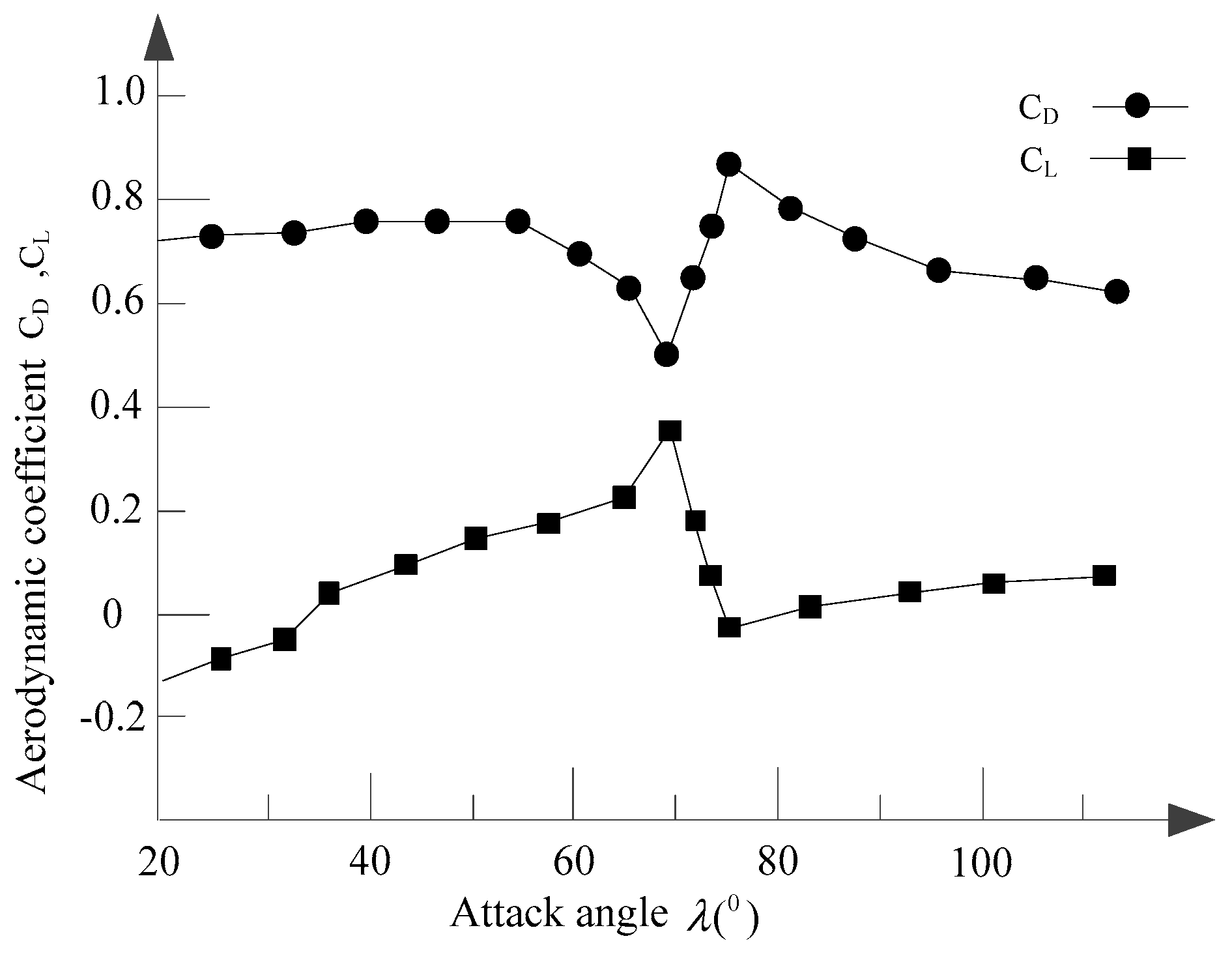
The lift and drag coefficients of the test model vs. attack angle λ at a yaw angle of 30° vary with the rainfall rate of 2.4 mm/min (Figure 5). It is seen that when λ is nearly 69 ° , the derivative of lift coefficients has a sudden change from a positive value to a negative value, whereas the derivative of drag coefficients has a sudden change from a negative value to a positive value. This is because it is sufficient to form the rivulets when λ 69 ° and the wind velocity is about 10 m/s. In addition, the upper rivulet reaches the critical angle, causing the boundary layer to trip, thus influencing the location of the separation point on the upper side of the test model.
To have the best-fitting functions of the measured aerodynamic lift and drag coefficients plotted in Figure 5, the first three terms of the Taylor’s series are used to express C D , C L with respect to λ as
{ C D ( λ ) = D 0 + D 1 λ + D 2 λ 2 / 2 + D 3 λ 3 / 6 C L ( λ ) = L 0 + L 1 λ + L 2 λ 2 / 2 + L 3 λ 3 / 6 .
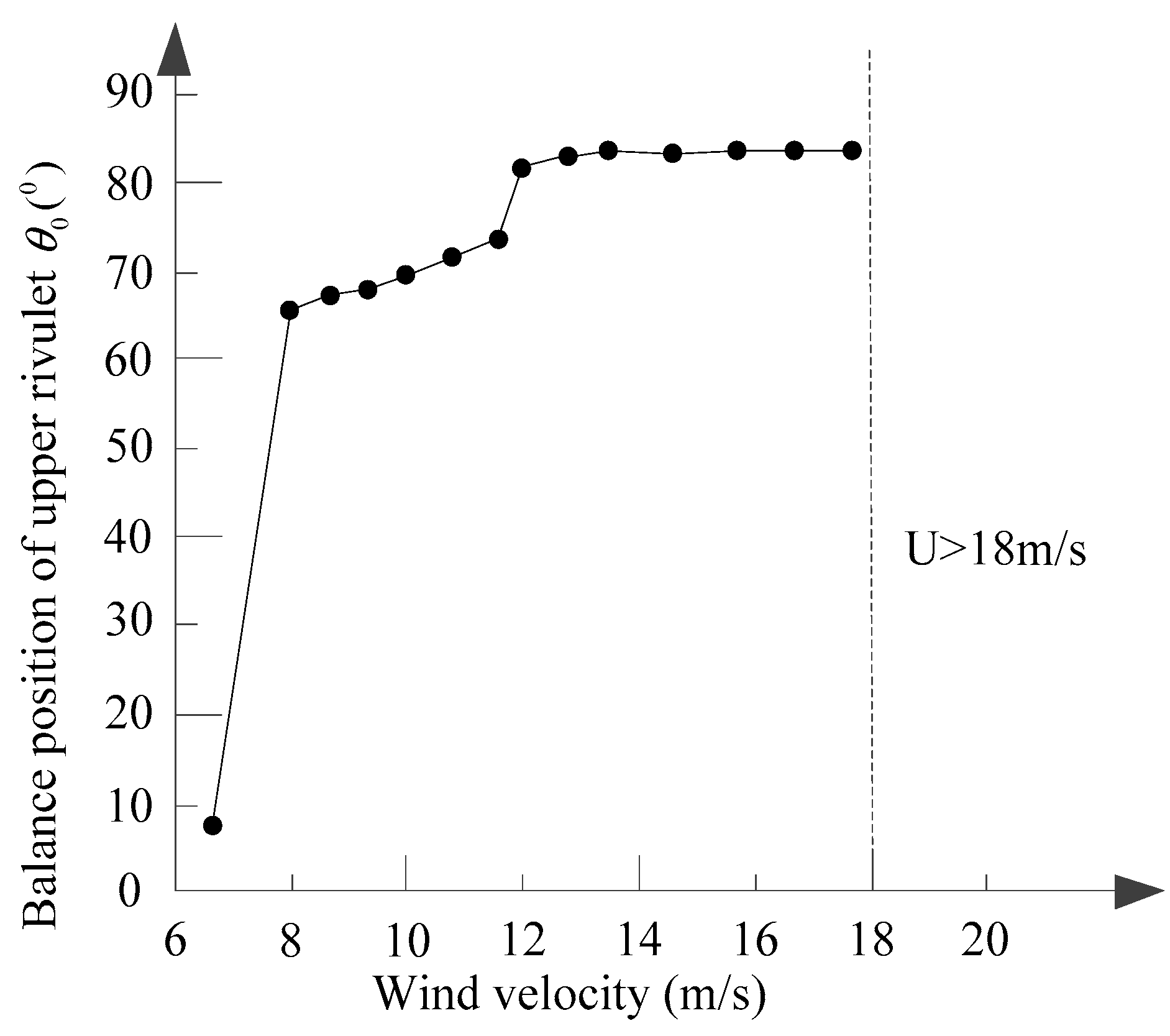
As shown in Figure 6, the balance position of the upper rivulet θ 0 changes with wind velocity U 0 at the rainfall rate of 2.4 mm/min. For U 0 < 8 m / s , there is no rivulet occurring at the surface of test model. For 8 m / s U 0 12 m / s , it is sufficient to form upper rivulet and oscillate around its balance position ( λ 69 ° ) where is the separation point on the upper side of the test model occurs. With further increasing of wind velocity, which is around 12 m / s U 0 18 m / s , the upper rivulet equilibrium position remains almost constant.

5. Numerical Study

As an example, firstly, the unstable swing of a single conductor with the upper rivulet is calculated with the above criteria to discuss the key factors. Moreover, the proposed model is solved by finite element method with the aerodynamic coefficients from simulated wind tunnel tests, by which the effects of wind, rainfall, aerodynamic damping on the large swing of overhead transmission lines are calculated.

5.1. The Key Factors for the Unstable Swing of the Conductor with the Criteria

As investigated above, the single conductor has a length of 1.8 m and a diameter of 30 mm, and the measured drag and lift coefficients are plotted in Figure 5. At the rainfall rate of 2.4 mm/min, the measured aerodynamic coefficients are divided into the two ranges, distinguished by the critical angle of 69 ° . The coefficients D i and L i ( i = 0 , 1 , 2 , 3 ) in Equation (27), obtained from the best fit, are listed in Table 2.
As observed from Figure 6, when λ 69 ° , the wind velocity is about 10 m/s, and the largest overhead conductor vibration may occur. In this section, we assume that the amplitude of the upper rivulet achieves a small value at wind velocity of U 0 < 8 m / s or U 0 > 12 m / s , and yields the following values for swing coefficients in Equation (17) as U p = 10 m / s , a 1 = 1 ° or a 1 = 2 ° (value of a 2 is determined by the decrease of the upper rivulet amplitude of order of 10%).
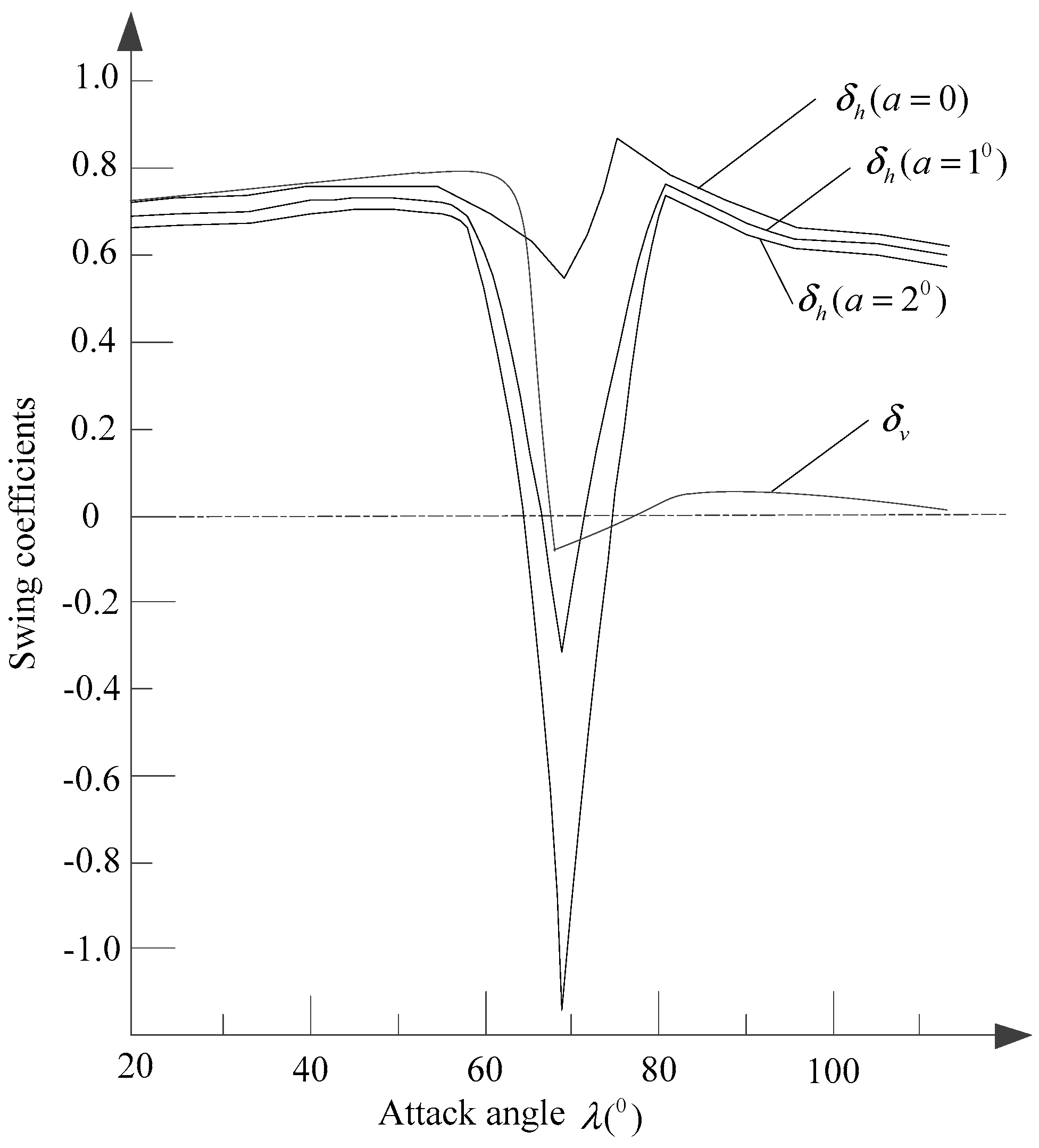
Figure 7 shows that the swing coefficients of the overhead conductor with attack angle λ vary with different δ . Using Equation (15), the swing coefficients of δ h get negative values when the critical angle λ 69 ° . For a 1 = 2 ° , unstable swing region of the overhead conductor is 64 ° < λ < 74 ° . For a 1 = 1 ° , the unstable swing region is 66 ° < λ < 72 ° . It is obvious that the unstable wing region for a 1 = 1 ° is less than that of a 1 = 2 ° . This is because the larger the upper rivulet motion, the higher the aerodynamic coefficient fluctuation. However, for a 1 = 0 , δ h always produces a positive value, and no unstable region appears. The reason why no unstable swing appeared is that the fixed upper rivulet has less effect on the aerodynamic coefficients when a 1 = 0 , which means the upper rivulet is fixed on the overhead conductor. Moreover, the swing coefficient of the cross-wind swings in wind flow normal to the overhead conductor axis was computed with Equation (26), and it is seen that when the critical angle is λ 69 ° ( 68 ° < λ < 78 ° ), the swing coefficients of δ h produce negative values. The criterion of the cross-wind swings in wind flow normal to the overhead conductor axis is equivalent to Den Hartog theory.

5.2. Numerical Calculation of Windage Yaw of the Overhead Conductor

As shown in Figure 8, the overhead conductors are suspended to a cat-head type tower with the suspension insulator strings, which are vertical under normal operation, and free to swing whenever there is an unbalanced force, such as wind, or wind-driven rain. If the clearance distance R between the tower head and the suspended conductor, which depends on the swing angle ψ , is smaller than the tolerable electric insulation distance, flashover may take place. In this study, the length of insulator string is assumed to be 4.97 m, and the maximum static distance of the tower head related to the conductor suspended on the bottom of the insulator string is 6.7 m.
To investigate the swing of the overhead conductor under rain-wind condition, the finite element method is considered to be an efficient means to calculate the windage yaw of the overhead conductor, as shown in Figure 9. A typical 500 kV transmission line section is selected as an example, which consists of two equal spans of 450 m, and no height differences exist between the suspension points. Each sub-conductor of the quad bundle conductor is LGJ-400/35, with a diameter of 30 mm, mass of 1349 kg per unit length, and elastic modulus of 6.5 × 10¹⁰ Pa. Structural damping ratio is 2% of critical damping for overhead conductor, as large experimental tests suggested [26]. To simplify the analysis, the suspension insulator string is modeled as a single rigid element, and only one sub-conductor is done by truss element; other sub-conductors, clamps, and spacers are neglected.
The wind field of this typical line section is B type open terrain, the roughness coefficient ε and the roughness length y 0 , are 0.16 m and 0.03 m [22], respectively. The peak swing amplitude of the overhead conductor are calculated by finite element method with Equations (6) and (15) under only wind (0 mm/min) condition and rain-wind condition (2.4 mm/min), as shown in Figure 10.
By the comparison of these two curves, it is easy to find that the peak swing amplitude of the overhead conductor under rain-wind condition is larger than that under only wind. This is because the wind is accompanied with raindrops. Under rain-wind condition, the raindrop impinging force has a certain contribution on the peak amplitude of the overhead conductor. Furthermore, as the wind velocity is at the near range of 10 m/s, the swing amplitude of the overhead conductor gets a large value of 3.5 m under rain-wind condition (2.4 mm/min). The reason why the large swing value occurs is that the gradients of the lift and drag coefficients have sudden changes and the aerodynamic damping c a gets a negative value and total damping c is small when the wind velocity nearly approaches to 10 m/s.
It is worthwhile to mention that the wind velocity of the maximum 10 min average velocity is considered for 15 year general 110 kV transmission lines, and for 30 year general 500 kV in the technical code for designing overhead transmission lines in China [27], and no wind-driven rain effect is taken into account in the determination of swing angle, which may underestimate the magnitude of the angle. The minimum permissible clearance distance under the rainfall condition may be enlarged by the reason that the sparking voltage decreased significantly. Table 3 shows clearance distances of flashover under different rainfall intensities, with the nominal voltage obtained by experimental tests [14,28]. For a rainfall intensity of 2.4 mm/min, the clearance distance of flashover is 1.833 m, with nominal voltage 500 kV.
Based on the structure of the cat-head type tower (Figure 8), where the length of insulator string is 4.97 m, and the maximum static distance of the tower head related to the conductor suspended on the bottom of the insulator string is 6.7 m, the clearance distance R is calculated with wind velocity and at rainfall rate of 2.4 mm/min. As shown in Figure 11, the clearance distance R is 1.92 m, which is very close to the clearance distance of flashover 1.83 m (Table 2), when the wind velocity is about 10 m/s. If under strong fluctuation of wind velocity, the clearance distance can easily be less than the clearance distance of flashover 1.83 m. Furthermore, when the wind velocity is at the range of 25 m/s, the clearance distance is 1.83 m and flashover may occur, which is obviously larger than the minimum permissible clearance 1.3 m (500 kV) recommended by the current design code for overhead transmission lines in China [27].

6. Conclusions

In this paper, an analytical model for describing large swing of overhead transmission lines under rain-wind condition is presented. The criterion for the unstable region of the overhead conductor is established for along-wind swings and cross-wind swings in wind flow normal to the overhead conductor axis. Moreover, the analytical model is solved by finite element method, with the aerodynamic coefficients from simulated wind tunnel tests, and some conclusions drawn from the whole paper are summarized as follows:
(1)
At the critical angle of λ 69 ° , the swing coefficients of δ h get negative values. For fixed upper rivulet, the criterion of the cross-wind swings in wind flow normal to the overhead conductor axis is equivalent to Den Hartog theory. For moving upper rivulet, the unstable region of the swing of the overhead conductor changes with the fluctuation range of the upper rivulet.
(2)
When wind velocity is close to 10 m/s, due to the rain-wind vibration, the peak swing amplitude of the overhead conductor under rain-wind condition reaches 3.5 m, nearly 2.5 times that of the swing amplitude of the overhead conductor only subjected to wind.
(3)
When the wind velocity approaches 10 m/s, due to the rain-wind vibration, the clearance distance R has a sudden drop, down to 1.92 m, which is very close to the clearance distance of flashover 1.83 m. If under strong fluctuation from wind velocity, the clearance distance can easily be less than the clearance distance of flashover. Moreover, at the range of 25 m/s, the clearance distance is 1.83 m, which is obviously larger than the minimum permissible clearance of 1.3 m (500 kV), recommended by the current design code for overhead transmission lines in China, and flashover may occur.
It should be noted that the proposed analytical model is still a preliminary model. Only the single conductor is studied, and the effects of sub-conductors, clamps, and spacers are neglected. Some assumptions are used in the model, and the criterion may be released in the further study. The systematic wind-rain tunnel tests or field measurements guided by the presented analytical model are needed.

Author Contributions

Chao Zhou established the model of rain-wind vibration. Jiaqi Yin analyzed data and computed with the model. Yibing Liu assisted with the theory and verified the analytical model. Chao Zhou wrote the manuscript in consultation with Jiaqi Yin and Yibing Liu.

Acknowledgments

This project is supported by the National Natural Science Foundation of China (No. 51575180), the Beijing Natural Science Foundation (No. 8152027), and the Fundamental Research Funds for the Central Universities (No. 2018MS020).

Conflicts of Interest

The authors declare no conflict of interest.

References

  1. Hu, Y. Study on trip caused by windage yaw of 500 kV transmission line. High Volt. Eng. 2004, 30, 9–10. [Google Scholar]
  2. Long, L.H.; Hu, Y.; Li, J.L.; Hu, T. Study on windage yaw of transmission line. High Volt. Eng. 2006, 32, 19–21. [Google Scholar]
  3. Hardy, C.; Watts, J.A.; Brunelle, J.; Clutier, L.J. Research on the Dynamics of Bundled Conductors at the Hydro-Quebec Institute of Research; Canadian Electrical Association Transactions, Engineering and Operation Division: Ottawa, ON, Canada, 1975. [Google Scholar]
  4. Hardy, C.; Bourdon, P. The influence of spacer dynamic properties in the control of bundle conductor motion. IEEE Trans. Power Appar. Syst. 1980, 99, 790–799. [Google Scholar] [CrossRef]
  5. Tsujimoto, K.; Yoshioka, O.; Okumura, T.; Fujii, K.; Simojima, K.; Kubokawa, H. Investigation of conductor swinging by wind and its application for design of compact transmission line. IEEE Trans. Power Syst. 1982, 100, 4361–4369. [Google Scholar] [CrossRef]
  6. Clapp, A.L. Calculation of horizontal displacement of conductors under wind loading toward buildings and other supporting structures. In Proceedings of the 37th Annual Conference on Rural Electric Power Conference, Kansas City, MO, USA, 25–27 April 1993. [Google Scholar]
  7. Hu, Y.; Wang, L.N.; Shao, G.W.; Liu, K.; Luo, C.K.; Chen, S.J.; Geng, C.Y. Influence of rain and wind on power frequency discharge characteristic of conductor-to-tower air gap. High Volt. Eng. 2008, 34, 845–850. [Google Scholar]
  8. Jiang, X.L.; Xi, S.J.; Liu, W.; Yuan, Y.; Dong, Y.; Xiao, D.H. Influence of rain on AC discharge characteristics of rod-plane air gap. J. Chongqing Univ. 2012, 35, 52–58. [Google Scholar]
  9. Jiang, X.L.; Liu, W.; Xi, S.J.; Yuan, Y.; Bi, M.Q.; Sun, Y.H. Influence of rain on positive DC discharge characteristic of rod-plane short air gap. High Volt. Eng. 2011, 37, 261–266. [Google Scholar]
  10. Yan, B.; Lin, X.S.; Luo, W.; Chen, Z.D.; Liu, Z.Q. Numerical study on dynamic swing of suspension insulator string in overhead transmission line under wind load. IEEE Trans. Power Deliv. 2010, 25, 248–259. [Google Scholar] [CrossRef]
  11. Xiong, X.F.; Weng, S.J.; Wang, J.; Li, Z.; Liang, Y. An online early warning method for windage yaw discharge of jumper towards “JG” type strain tower considering corrected by rainfall. Power Syst. Protect. Control 2015, 43, 136–143. [Google Scholar]
  12. Mazur, K.; Wydra, M.; Ksiezopolski, B. Secure and time-aware communication of wireless sensors monitoring overhead transmission lines. Sensors 2017, 17, 1610. [Google Scholar] [CrossRef] [PubMed]
  13. Wydra, M.; Kisala, P.; Harasim, D.; Kacejko, P. Overhead transmission line sag estimation using a simple optomechanical system with chirped fiber bragg gratings. Part 1: Preliminary measurements. Sensors 2018, 18, 309. [Google Scholar] [CrossRef] [PubMed]
  14. Geng, C.Y.; Wei, D.; He, X. Rain effect on frequency breakdown voltage. High Volt. Appar. 2010, 46, 103–105. [Google Scholar]
  15. Zhu, K.J.; Li, X.M.; Di, Y.X.; Liu, B. Asynchronous swaying character and prevention measures in the compact overhead transmission line. High Volt. Appar. 2010, 36, 2717–2723. [Google Scholar]
  16. Zhu, K.J.; Di, Y.X.; Li, X.M.; Fu, D.J. Numerical simulation for asynchronous swaying of overhead transmission line. Power Syst. Technol. 2009, 33, 202–206. [Google Scholar]
  17. Zhang, H.J.; Zhao, J.F.; Cai, D.Z.; Niu, H.W. Wind tunnel test on the influence of col features on wind speed distribution. J. Exp. Fluid Mech. 2014, 28, 25–30. [Google Scholar]
  18. Holmes, J.D. Along-wind response of lattice tower-II, aerodynamic damping and deflections. Eng. Struct. 1996, 18, 483–488. [Google Scholar] [CrossRef]
  19. Lou, W.J.; Yang, Y.; Lu, Z.B.; Zhang, S.F.; Yang, L. Windage yaw dynamic analysis methods for transmission lines considering aerodynamic damping effect. J. Vib. Shock 2015, 34, 24–29. [Google Scholar]
  20. Stengel, D.; Mehdianpour, M. Finite element modeling of electrical overhead line cables under turbulent wind load. J. Struct. 2014, 2014. [Google Scholar] [CrossRef]
  21. Zhou, C.; Liu, Y.B.; Ma, Z.Y. Investigation on aerodynamic instability of high-voltage transmission lines under rain-wind condition. J. Mech. Sci. Technol. 2015, 29, 131–139. [Google Scholar] [CrossRef]
  22. Simiu, E.; Scanlan, R.H. Wind Effects on Structures; Wiley: New York, NY, USA, 1996. [Google Scholar]
  23. Marshall, J.S.; Palmer, W.M.K. The distribution of raindrops with size. J. Atmos. Sci. 1948, 5, 165–166. [Google Scholar] [CrossRef]
  24. Hikami, Y.; Shiraishi, N. Rain-wind induced vibrations of cables in cable stayed bridges. J. Wind Eng. Ind. Aerodyn. 1988, 29, 409–418. [Google Scholar] [CrossRef]
  25. den Hartog, J.P. Transmission line vibration due to sleet. Trans. Am. Inst. Electr. Eng. 1932, 51, 1074–1077. [Google Scholar] [CrossRef]
  26. Roshan, F.M.; McClure, G. Numerical modeling of the dynamic response of ice-shedding on electric transmission lines. Atmos. Res. 1998, 46, 1–11. [Google Scholar] [CrossRef]
  27. Northeast Electric Power Design Institute of National Electric Power Corporation. Design manual of High Voltage Transmission Lines for Electric Engineering; China Electric Power Press: Beijing, China, 2003. [Google Scholar]
  28. Geng, C.Y.; Chen, S.J.; Liu, S.Y. Experimental study of the raining effect on frequency breakdown voltage of air-gap. High Volt. Appar. 2009, 45, 36–39. [Google Scholar]
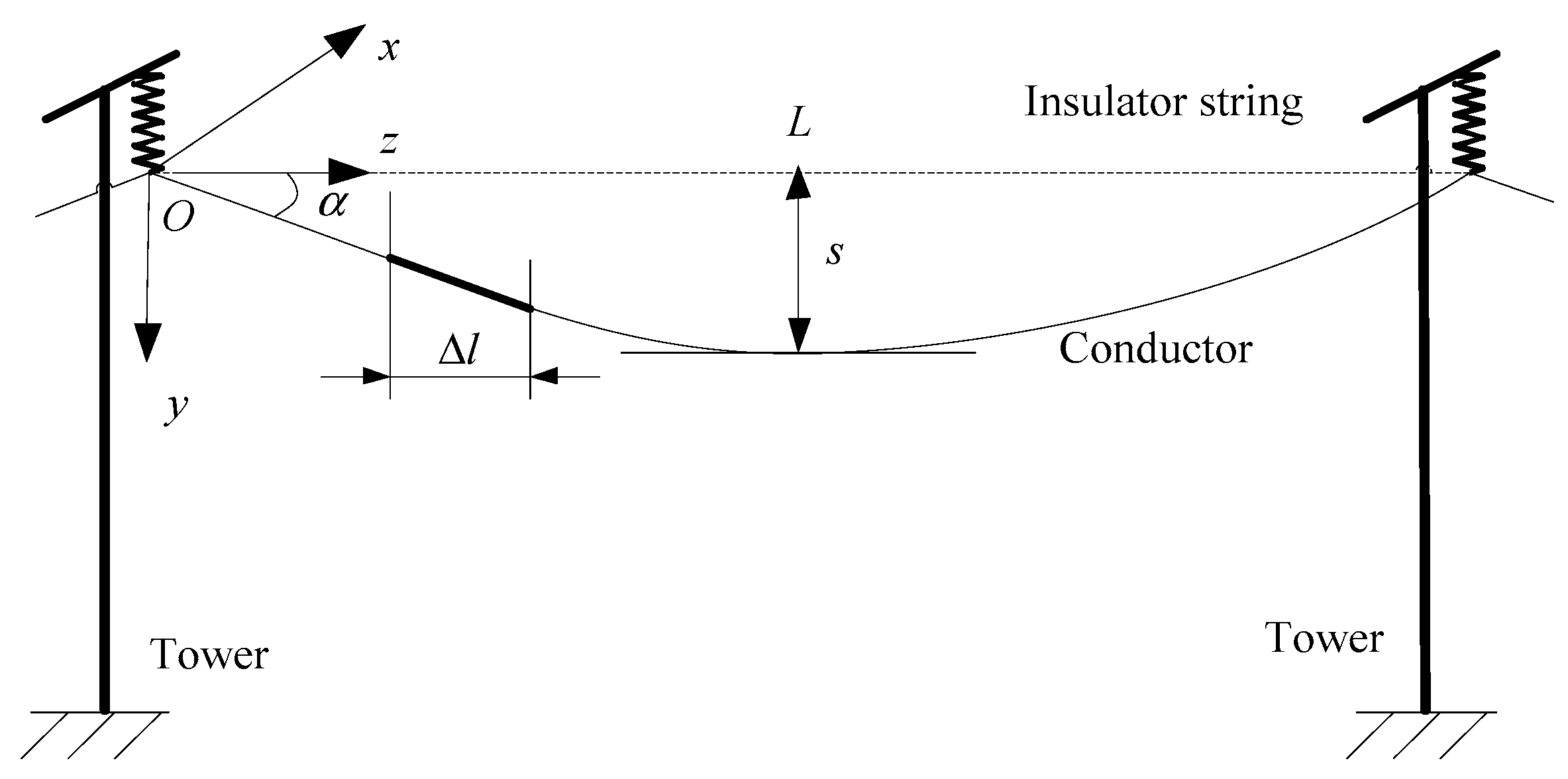
Figure 1. Schematic representation of one-span tower-line structure section.
Energies 11 01092 g001
Figure 2. Relative space position between wind and conductor.
Energies 11 01092 g002
Figure 3. Relative velocity of wind and motion of cylinder.
Energies 11 01092 g003
Figure 4. Experimental set-up of rain-wind tunnel test: (a) schematic of rain-wind experimental set-up, (b) Photoshop of rain-wind tunnel test with spray nozzles.
Energies 11 01092 g004
Figure 5. Aerodynamic coefficients vs. attack angle of λ (when β = 30 ° ).
Energies 11 01092 g005
Figure 6. Upper rivulet equilibrium position θ 0 vs. wind velocity U 0 .
Energies 11 01092 g006
Figure 7. Swing coefficients of the overhead conductor with different δ .
Energies 11 01092 g007
Figure 8. Schematic of windage yaw of the overhead conductor.
Energies 11 01092 g008
Figure 9. Finite element model of the overhead line section.
Energies 11 01092 g009
Figure 10. Peak swing amplitude of the overhead conductor with wind and rain-wind condition.
Energies 11 01092 g010
Figure 11. Clearance distance R with wind velocity, for a rainfall rate of 2.4 mm/min.
Energies 11 01092 g011
Table 1. Rainfall intensity with rainfall levels.
Rainfall LevelsRainfall Intensity (mm)
24 h12 h6 h1 min
Heavy25.0–49.915.0–29.96.0–11.91.00–2.67
Rainstorm50.0–99.930.0–69.912.0–24.92.68–4.24
Heavy Rainstorm100.0–249.970.0–139.925.0–59.94.25–6.25
Super Rainstorm≥250.0≥140.0≥60.0≥6.26
Table 2. The coefficients in Taylor’s form the best fit for the measured data at the rainfall rates of 2.4 mm/min.
RangeD0D1D2D3L0L1L2L3
λ < 69°1.1−0.0370.00055−0.000005−0.2810.00440.00010.0000003
λ 69°−32.461.109−0.0060.00000622.082−0.7220.0039−0.000005
Table 3. Clearance distances (m) of flashover under different rainfall intensity with the nominal voltage.
Nominal Voltage (kV) Rainfall Intensity (mm/min)
02.44.89.614.4
1100.250.2630.2820.3020.311
2200.550.6400.6690.6970.711
3300.901.0761.1101.1381.153
5001.201.8331.8631.8801.891