Article

A Real-Time Simulink Interfaced Fast-Charging Methodology of Lithium-Ion Batteries under Temperature Feedback with Fuzzy Logic Control

1
School of Electrical Engineering, Pusan National University, Busandaehak-ro 63 Beon-gil 2, Busan 46241, Korea
2
School of Electrical Engineering and Computer Science, National University of Sciences and Technology, Islamabad 44000, Pakistan
3
Department of Cogno-Mechatronics Engineering, Pusan National University, Busandaehak-ro 63 Beon-gil 2, Busan 46241, Korea
*
Author to whom correspondence should be addressed.
Energies 2018, 11(5), 1122; https://doi.org/10.3390/en11051122
Submission received: 2 April 2018 / Revised: 28 April 2018 / Accepted: 1 May 2018 / Published: 2 May 2018
(This article belongs to the Section D: Energy Storage and Application)

Abstract

:
The lithium-ion battery has high energy and power density, long life cycle, low toxicity, low discharge rate, more reliability, and better efficiency compared to other batteries. On the other hand, the issue of a reduction in charging time of the lithium-ion battery is still a bottleneck for the commercialization of electric vehicles (EVs). Therefore, an approach to charge lithium-ion batteries at a faster rate is needed. This paper proposes an efficient, real-time, fast-charging methodology of lithium-ion batteries. Fuzzy logic was adopted to drive the charging current trajectory. A temperature control unit was also implemented to evade the effects of fast charging on the aging mechanism. The proposed method of charging also protects the battery from overvoltage and overheating. Extensive testing and comprehensive analysis were conducted to examine the proposed charging technique. The results show that the proposed charging strategy favors a full battery recharging in 9.76% less time than the conventional constant-current–constant-voltage (CC/CV) method. The strategy charges the battery at a 99.26% state of charge (SOC) without significant degradation. The entire scheme was implemented in real time, using Arduino interfaced with MATLABTM Simulink. This decrease in charging time assists in the fast charging of cell phones and notebooks and in the large-scale deployment of EVs.

1. Introduction

The extensive use of petrol, diesel, and other fossil fuels in automobiles has had adverse effects on global warming and greenhouse gas (GHG) emissions [1,2,3]. In addition to global warming and GHG, the fossil fuel prices are increasing rapidly, which is a setback in the automobile industry. To overcome these economic and pollution problems, electric vehicles (EVs) and plug-in hybrid electric vehicles (PHEVs) are becoming a transportation secondary option [4,5,6,7,8]. By 2050, the annual sale of EVs and PHEVs is expected to reach approximately 100 million [9]. This growth in the demand for EVs and PHEVs has captivated many researchers to design rechargeable batteries [10,11,12]. Lithium-ion, lead acid, and nickel–metal hydride(NiMH) batteries have been adopted as energy charge storage devices in EVs and PHEVs [13]. The lithium-ion battery is preferred because of its long life cycle, reliability, high energy density, low toxicity, low self-discharge rate, high power density, and high efficiency [14,15,16,17].
A single cell of a lithium-ion battery has a low voltage. Therefore, a combination of cells is used in series to boost the voltage, but its outcomes are deep discharging, overcharging, and a decrease in battery storage capacity. The undercharged and overcharged conditions influence the life cycle of a battery [18]. The undercharged condition prevents reaching the maximum storage capacity, and the overcharged condition damages the battery physically. In addition to these deficiencies, a critical concern is the long charging time.
In recent years, decreasing the charging time of lithium-ion batteries without affecting their capacity and physical condition has been a serious concern for researchers. For the charging of lithium-ion batteries, different charging techniques, such as constant current and constant voltage (CC/CV), pulse charging (PC) algorithm, model-based charging, and multistage current charging algorithm (MSCC), have been reported [19,20,21,22,23,24,25,26,27,28,29,30,31,32,33,34]. The CC/CV techniques is computationally efficient and can be implemented easily. This technique has two main steps. In the first step, a constant current is provided to the battery until the battery voltage reaches the preset voltage. In the second interval, the constant voltage mode is turned ON, and the battery current begins to decrease exponentially until it reaches a preset small charging current [19]. In this method, different sensors are required to check the current and battery voltage. Many variants of the CC/CV charging algorithm have been reported, e.g., the double-loop charger (DL–CC/CV). In the DL–CC/CV technique, the role of the current sensor is eliminated by taking the feedback of the battery voltage [20]. Tsang and Chan presented the concept of the PC algorithm. In the PC algorithm, the main part is to control the frequency of the pulse to check the response of the current [21]. The optimal frequency can be achieved at low battery impedance, resulting in the maximum charging current.
Similarly, the MSCC algorithm has been implemented to charge the battery, in which different charging currents are applied at different intervals, but the hindrance is how to determine the appropriate current for different charging intervals. For this purpose, a controller or computer is necessary to calculate the values. The Taguchi methodology decides the charging current by estimating the state of charge (SOC) of the battery [22]. In the model-based charge control, the estimation of the SOC is a crucial step. Several previous studies have discussed equivalent circuit models to estimate the SOC. However, the SOC and capacity determination is still a challenging task because it is difficult to measure it with sensors. Recently, Wei and coauthors [23,24,25] presented recursive online models to estimate the SOC of a lithium-ion battery. Wei et al. [23] indicated the problem of biased results for the estimation of the SOC using conventional identification methods in the model-based charging technique. They proposed a recursive least square-based Frisch scheme to enhance the model identification and estimation of the SOC in the presence of noise. In their subsequent work, Wei et al. [24] proposed a multi-timescale method for dual estimation of the SOC with the online battery model. Their results suggest that this method determines SOC and capacity with fast convergence and high accuracy. In a recent study of Wei et al. [25], a novel recursive total least square-based observer method was proposed to suppress the noise effect in a model. The authors were able to estimate the SOC with high accuracy. However, the equivalent circuit model for a lithium-ion battery varies from a simple representation to a very complex mathematical form. A simple model can simulate the dynamic characteristics of the battery up to a certain accuracy. On the other hand, a complex model shows much better results as compared to the simple one, but these are difficult to implement in real time.
Furthermore, Guo et al. [26] reported another way to improve the charging time and life cycle using a universal voltage protocol. Zhang et al. [27] proposed that a dynamic optimization algorithm can be utilized to determine the optimal charging time. Liu et al. [28] implemented the ant colony algorithm to find the optimal current to charge a lithium-ion battery. In addition to these methodologies, a fuzzy logic controller (FLC) could be beneficial [29,30,31,32,33,34]. Huang et al. [29] used FLC to find the charging current for different intervals, in which the inputs of the controller were the temperature rise and the deviation of the temperature rise. The proposed methodology increased the charging efficiency of the battery but required more time to charge it. Lee et al. [30,34] also implemented the FLC to equalize the voltages of a cell in a string. This reduced the equalization time of voltages in a string compared to the conventional process. Ho et al. [31] implemented the FLC with the Taguchi method to improve the charging time. The Taguchi method was utilized to determine the optimal output membership function of the FLC. The temperature of the battery and the gradient of temperature rise were the inputs of the FLC. Lyn et al. [32] used battery voltage and charging current as inputs of the FLC, and the longer time consumption for higher charging efficiency was the limitation of this methodology. Hsieh et al. [33] used the FLC by monitoring the charging state of the battery and replaced the CV mode of the CC/CV method with the proposed methodology. This only reduces the charging time of the CV mode; however, the overall charging time improvement was not so high.
This paper proposes the MSCC technique embedded with fuzzy logic and temperature feedback for series-connected lithium-ion batteries. The voltage and temperature were fed to the controller to find the optimal charging current within the safe temperature limit. The proposed method charges the battery in a faster way. Also, the temperature control unit avoids the effects of fast charging on the aging mechanism and protects the battery from an overvoltage condition. The proposed technique was implemented on a three-cell lithium-ion battery. Figure 1 presents the general diagram of the proposed system. The FLC and temperature control units were implemented using Arduino MEGA 2560 interfaced with MATLABTM Simulink 2017. Extensive testing and comprehensive analysis were done to validate the proposed technique. The charging time, charging capacity, and life cycle of the battery are discussed.
The paper is organized as follows. Section 2 describes the fuzzy logic control temperature-feedback battery-charging system. Section 3 presents the experimental setup. Section 4 discusses the results. The conclusions are summarized in the last section.

2. Theory

2.1. Background of Fuzzy Logic for the Lithium-Ion Battery

The lithium-ion battery is a very complex nonlinear system. Therefore, it is very difficult to determine the precise mathematical model of the lithium-ion battery. Consequently, it is necessary to use a controller, which does not require a precise mathematical model of a battery. In this regard, a fuzzy logic controller is a better choice because it is used for nonlinear mapping of the input data to scalar output data. In this study, a fuzzy logic controller was implemented to enhance the charging efficiency of a lithium-ion battery.
A fuzzy logic-controlled system can be divided into four parts: fuzzification, fuzzy rule base, fuzzy inference engine, and defuzzification [35,36,37,38]. Figure 2 presents a generic overview of the FLC.
Fuzzification: This converts the input true data value into fuzzy linguistic sets, using a membership function. Fuzzy rule base: This is the main component of the system and the operating control of the system designed in it. In addition, the control law parameters of the system are stored in a database. This requires considerable professional skill and experience to design a fuzzy rule base. Inference engine: This is an operating method that converts a fuzzy linguistic input to a fuzzy linguistic output according to the control law defined in a fuzzy rule base. Defuzzification: This converts the fuzzy linguistic output to the true value according to the membership function.

2.2. Fuzzy Logic Controller Design

A fuzzy logic base Arduino controller is proposed to control the charging current of the battery. The fuzzy controller has two inputs. The first is the lowest single-cell voltage of the string (VB), and the other one is the highest voltage difference between the two cells of the battery (Vd), as shown in Figure 2. The fuzzifier changes the input data to linguistic fuzzy sets, and the inference engine then determines the optimal value using the input fuzzy data and rule base. The rule base, which is stored in the database of the system, is listed in Table 1. Finally, the defuzzifier changes the fuzzy linguistic sets of the output in the numerical value of the charging current Icharge.
The five linguistic variables used in Table 1 are: VS (very small), S (small), M (medium), L (large), and VL (very large). When the variable appears on the horizontal top row in Table 1 (blue color), it shows the voltage difference; similarly, when appearing in the leftmost column of Table 1 (green color), it shows the battery voltage levels, and, when appearing inside Table 1 (black color), it represents different stages of the charge current. Lee et al. [30] used a similar set of rule bases. The fuzzy variables for VB, Vd, and Icharge are µB, µA, and µo, respectively. Figure 3 shows the sets of membership functions of the fuzzy variables.
In defuzzifier and inference engine, the method of the center of gravity and the max–min composition were used. on the basis of the rapid charging control strategy, the fuzzy control rules for battery charging are defined as follows [34,37]:
R a : IF   V d a   is   LGSV d a   and   V B a   is   LGSV B a   THEN   I charge a   is   LGSI charge a
where LGSI and LGSV are the signed disturbance linguistic values in the ath variable of the IO fuzzy sets. The proposed rule base is already defined in Table 1. The design of the proposed fuzzy logic controller is as follow:
  • Step 1: The true value of w i j is calculated from the ith input value of the membership function for x and from the jth input value of the membership function for y:
    w ij = min { µ Ai ( x ) ,   µ Bj ( y ) } ;   for   i = 1 ,   2 ,   5   and   j = 1 ,   2 ,   5
  • Step 2: Using w i j and each rule for the kth membership output function, the fuzzy output value µ o i j   ( z ) is:
    µ oij   ( z ) = min { w ij ,   µ ok   ( z ) } ;   for   k = 1 ,   2 ,   5
  • Step 3: The fuzzy set for output z is
    µ out   ( z ) = max { µ o 11   ( z ) ,   µ o 12   ( z ) ,   µ o 54   ( z ) ,   µ o 55   ( z ) }
  • Step 4: The charging current of the battery (Icharge), using the center of gravity method and defuzzification process is expressed as follows:
    I charge = a = 1 b µ out   ( z 1 ) · ( z 1 ) a = 1 b µ out   ( z 1 )
The output of the fuzzy logic controller is the numerical value of the Icharge based on Vd and VB. Figure 4 shows the 3-D graphical representation of the fast-charging fuzzy logic controller, where Vd is presented on the x-axis, VB on the y-axis, and Icharge on the z-axis. Vd and VB are the inputs, and Icharge is the output of the fuzzy controller. The charging current is adjusted automatically on the basis of the value of Vd and VB. Figure 4 indicates that, when the Vd is high, it indicates that one of the battery cells is at a lower potential with reference to the other. Thus, injecting a high current helps to charge the cell in minimum time. However, at the same time, it is necessary to ensure that this high value of current does not affect the battery life. For that particular reason, the temperature control unit was been added which continuously measures and adjusts the current value accordingly. The detail of the temperature control unit are discussed in Section 2.3.

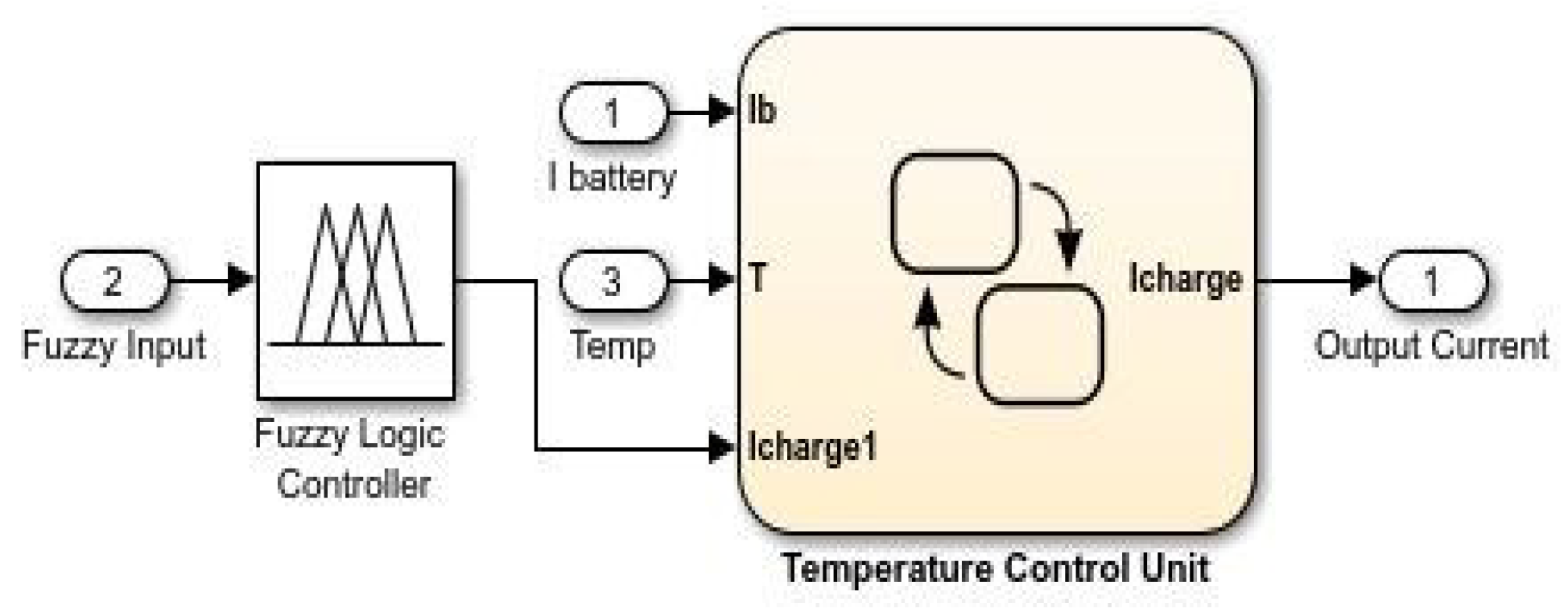
2.3. Temperature Control Unit

The basic function of the temperature control unit is to maintain the battery temperature to a safe limit predefined by the manufacturer. Figure 5 shows the temperature control flow chart of the Samsung ICR18650-26F lithium-ion battery. In the Samsung ICR18650-26F lithium-ion battery, the charging temperature limit is 0–45 °C [39]. Hence, the temperature upper limit check was set to 40 °C to be safe.
The temperature control unit continuously senses the battery current (Ib) and the battery temperature (T). If the temperature is below 40 °C, the fuzzy logic output current is supplied to the battery. When the battery temperature (T) crosses the 40 °C limit, the controller compares the battery current (Ib) with the range defined in the flow chart. If Ib lies between 3.6 and 4.1 A, the controller sets Icharge to 3.5 A and continuously checks the temperature every 7 s to verify whether the temperature is increasing or is maintained at the same level. If the temperature is outside the defined limits, it reduces the Icharge to 3 A. Similarly, if the temperature is at the same level, i.e., greater than the defined limit, the controller sets Icharge to 2.6 A, which is the safe current for a battery, as defined by the manufacturer [39].

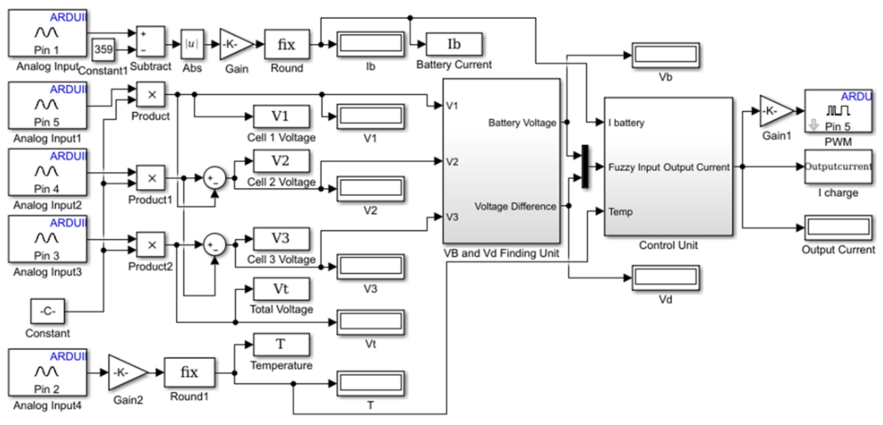
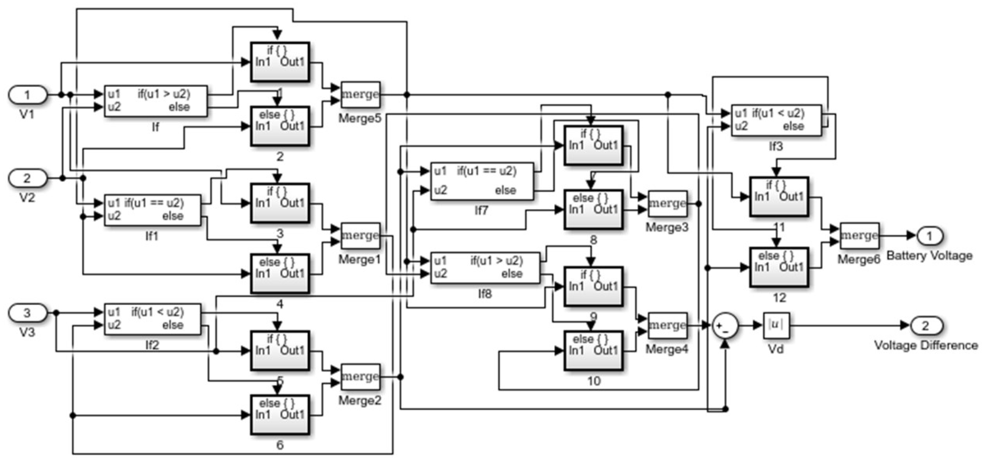
3. Experimental Setup

The Samsung ICR18650-26F lithium-ion battery was used in the current experimental setup to analyze the methodology. A string of three cells connected in series was used. Figure 6 shows the experimental setup, with different sensors used to measure and monitor the parameters, such as battery voltage, charge current, and temperature.
The proposed technique was implemented using Arduino Mega 2560. MATLABTM Simulink 2017 was used to program the controller; the real-time data were measured and monitored in MATLABTM Simulink. The data were also recorded in the workspace. Figure 7, Figure 8 and Figure 9 present the Simulink configuration of the battery-charging system.
Figure 7 shows the real-time measuring and monitoring system of the battery charging on Simulink MATLABTM. The sensor output to the Arduino analogue pins were converted to true values. These values were then passed to module 2, as shown in Figure 8. Figure 8 shows the scheme followed to of find Vd and VB.
Figure 9 presents the fuzzy logic controller and temperature control unit. Vd and VB are the inputs of the fuzzy logic controller. The output of the fuzzy logic controller is the input of the temperature control unit along with the battery temperature (T) and the battery current (Ib). The temperature control unit was programed using the state flow chart of MATLABTM.

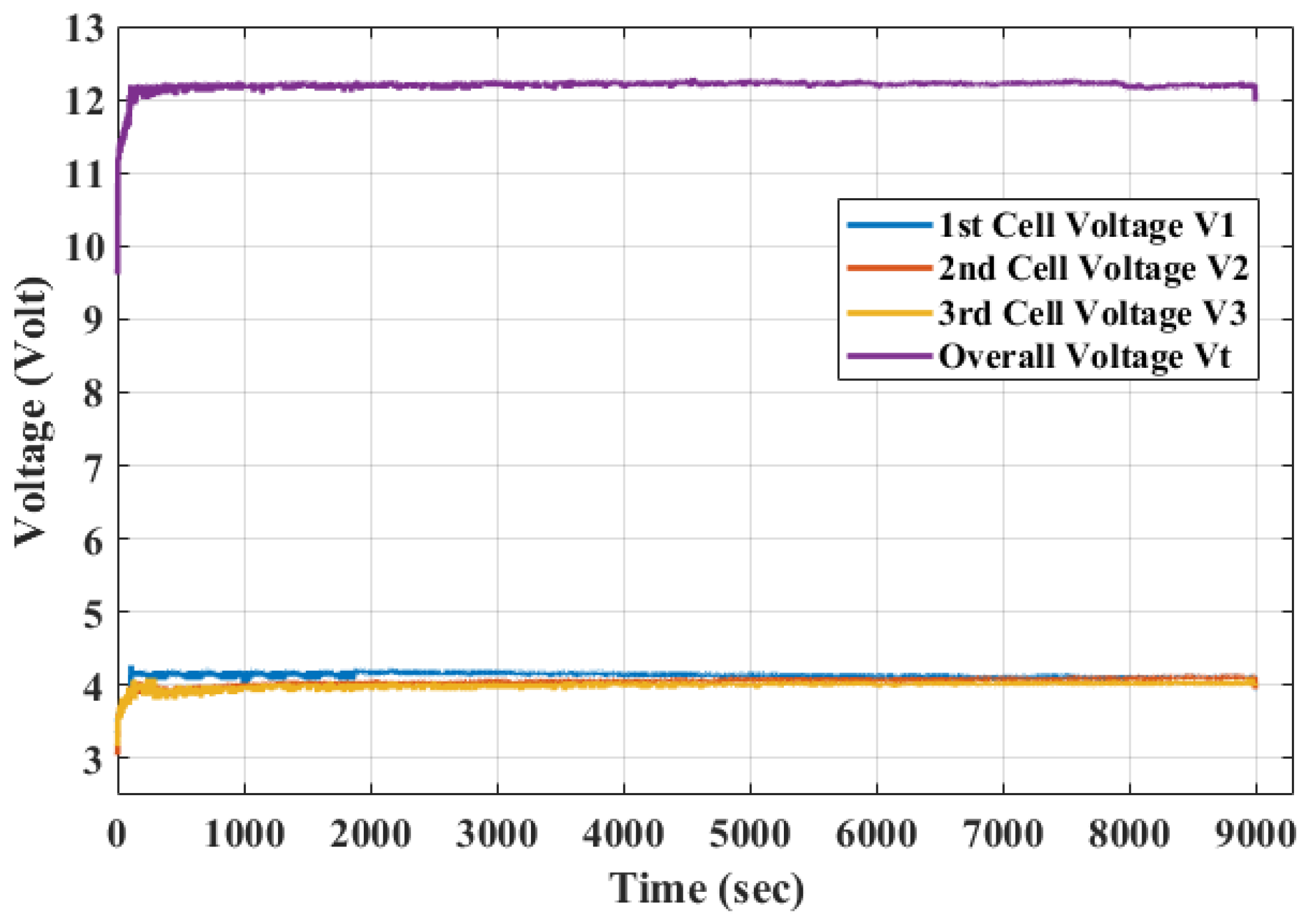
4. Results and Discussion

A wide range of electrical equipment, such as notebooks, cell phones, MP3 players, and EVs, are operated by batteries. These batteries take several hours to charge, which leads to a long out-of-service time. Therefore, a reduction in battery charging time has become a significant issue. The basic aim of fast charging is to charge the battery in a fast, safe, and efficient manner.
Figure 1 gives a general overview of the proposed fast-charging methodology. Three series of connected lithium-ion cells were used. The sensors feed the states of the battery to the controller, and the controller is interfaced with MATLABTM Simulink. Figure 2 shows the fuzzy logic control system in detail. Table 1 and Figure 3 present the rule base and membership functions values, respectively. Figure 4 shows the relationship between the inputs and output of the FLC. Figure 5 presents a flow chart of the temperature control unit of the battery, and Figure 6 shows the experimental setup of the proposed charging system. Figure 7, Figure 8 and Figure 9 present the MATLABTM Simulink measuring, monitoring, and control system. Figure 10 and Figure 11 present the charging profile of the battery using the conventional and proposed way of charging, respectively. Figure 12 shows the current profile of battery charging using the proposed technique. Figure 13 and Figure 14 show the temperature during the proposed charging methodology. Figure 15, Figure 16 and Figure 17 present the battery capacity and discharging curves. The comparison of the life cycle tests between the proposed and the conventional charging methodology is shown in Figure 18. Table 2 summarizes the results of this research.
Several experiments were performed with different initial cell voltages to verify the proposed technique. First, the battery was charged using the CC–CV method (defined by the manufacturer) to determine its normal charging time [39]. The initial cell voltages were V1 = 3.391 V, V2 = 3.263 V, and V3 = 3.353V. Figure 10 shows the conventional charging profile of the battery. The process took 8997 s (2.5 h) to fully charge the battery (see Figure 10); the same charging time (2.5 h) was also mentioned by the manufacturer [39].
The proposed charging technique was applied to a three-cell battery with different initial cell voltages. In this case, the initial voltages were V1 = 3.393 V, V2 = 3.367 V, and V3 = 3.273 V. Figure 11 and Figure 12 show the charging profiles using the proposed technique.
The battery took 8118 s (2.25 h) to charge, as shown in Figure 11 and Figure 12. This was almost 15 min (879 s) less than the normal charging time. The spike shown in the graph was attributed to the over-temperature limit. When the temperature increased to more than 40 °C, the charging current reduced to manage the temperature, as described in Section 2.3 and shown in the magnified part of Figure 11. The temperature was monitored and measured using a thermocouple and FLUKE VT04A visual infrared IR thermometer. The thermocouple provided the input directly to the controller, and an IR thermometer was used to monitor the temperature manually. Figure 13 presents some of the images captured during the proposed charging using the IR thermometer.
The temperature of the cells was 27.3 °C at the beginning of charging, as shown in Figure 13a. As charging began, the temperature started to rise because of the high charging current and reached 40.9 °C (Figure 13c). The temperature control unit then reduced the charging current to control the temperature of the battery. Owing to the reduction in the charging current, a spike in the charging curve was observed (Figure 11). The temperature then began to decrease because the battery started to draw a low current (Figure 13e–g). After charging, the temperature of the battery was 27.4 °C, as shown in Figure 13h. The temperature-versus-time graph of the battery during charging is shown in Figure 14.
The charging capacity of the battery using this technique was approximately 99.26%, which was the same as that of a 1 C charge. The proposed technique did not reduce the life cycle of the battery because the temperature of the battery remained within the safe limit (below 45 °C). Figure 15 shows the discharging curve of the battery at 0.23 C (0.6 A).
Figure 16 shows the relationship between the voltage and the capacity (mAh) of the battery during the discharging condition.
Figure 17 presents the discharging curves of the battery at 0.38 C of 26th cycle, 0.8 C of 24th cycle, 1 C of 21st cycle, and 2 C of 29th cycle. These curves show that the battery was charged almost at its full capacity (2600 mAh) using the proposed technique.
Using the proposed technique, the charging time of the battery was decreased without affecting its life cycle and charge capacity. A total of 50 experiments were performed to validate the proposed technique. The comparison of cycle life tests between the proposed and the CCCV technique is shown in Figure 18.
Some other experiments were performed by changing the number of fuzzy variables and the value of the membership functions. By adopting three fuzzy variables, the decrease in the charging time was 3 to 4 min, and by increasing the value of the membership function, the temperature increased at a rapid pace. In the proposed technique, five fuzzy variables were selected with the membership value mentioned in Table 1 and Figure 3. Different experiments were performed with different initial voltages. The results are shown in Table 2.
In recent years, many intelligent charging methods have been applied using microprocessors and computers. One of these techniques is to control the charging process by sensing the tuning points. These tuning points have been selected based on the battery temperature, voltage, and lapsed charging time [40]. The control algorithm changes the charging behavior only at the tuning points, and the period outside the tuning points is unaffected. The ant colony algorithm was used to optimize the MSCC profile [28]. This optimization algorithm does not use the real-time measurements of the state of the battery to change the charging current, but rather finds the best charging profile for the entire process. Saberi et al. [41] applied a genetic algorithm (GA) to solve the charging problem for the lithium-ion battery. The performance of the GA was dependent on the system accuracy; the robustness of the GA decreased because of the noise and time variance properties of the battery. Chen et al. [42] used the grey prediction technique for battery charging without taking the temperature into consideration. The advantages of the proposed methodology over the previous techniques are that it is easy to implement and that all battery states are considered during the charging state. Therefore, the battery can be protected from overvoltage, overcharging, and overheating conditions. The results show an almost 15 min decrease in the charging time without affecting the capacity and life cycle, which is significant for the battery life.

5. Conclusions

A real-time multistage current charging technique embedded with fuzzy logic and temperature feedback was implemented in this paper. The proposed technique was designed and programmed in MATLABTM Simulink. The methodology was implemented using a three-cell lithium-ion battery. The results revealed a 9.76% reduction in the charging time compared to the conventional way of charging. This method of charging does not decrease the charging capacity and charging efficiency. The temperature feedback was introduced to protect the battery from overheating. The experimental results show that the proposed charging technique for charging a battery is faster and safer than the conventional techniques.

Author Contributions

Hee-Je Kim and Muhammad Umair Ali have conceptualized the idea of this study. The experimental setup has developed and analyzed by Muhammad Umair Ali and Sarvar Hussain Nengroo. Muhammad Adil khan and Kamran Zeb contributed in the controller programming. The initial manuscript prepared by Muhammad Umair Ali and Muhammad Ahmad Kamran. Hee-Je Kim supervised and finalized the research manuscript.

Acknowledgments

The work was supported by BK 21 plus.

Conflicts of Interest

The authors declare no conflict of interest.

References

  1. Hannan, M.; Azidin, F.; Mohamed, A. Hybrid electric vehicles and their challenges: A review. Renew. Sustain. Energy Rev. 2014, 29, 135–150. [Google Scholar] [CrossRef]
  2. Budzianowski, W.M. Negative carbon intensity of renewable energy technologies involving biomass or carbon dioxide as inputs. Renew. Sustain. Energy Rev. 2012, 16, 6507–6521. [Google Scholar] [CrossRef]
  3. Sulaiman, N.; Hannan, M.; Mohamed, A.; Majlan, E.; Daud, W.W. A review on energy management system for fuel cell hybrid electric vehicle: Issues and challenges. Renew. Sustain. Energy Rev. 2015, 52, 802–814. [Google Scholar] [CrossRef]
  4. Poullikkas, A. Sustainable options for electric vehicle technologies. Renew. Sustain. Energy Rev. 2015, 41, 1277–1287. [Google Scholar] [CrossRef]
  5. Hofmann, J.; Guan, D.; Chalvatzis, K.; Huo, H. Assessment of electrical vehicles as a successful driver for reducing CO2 emissions in china. Appl. Energy 2016, 184, 995–1003. [Google Scholar] [CrossRef] [Green Version]
  6. Casals, L.C.; Martinez-Laserna, E.; García, B.A.; Nieto, N. Sustainability analysis of the electric vehicle use in europe for CO2 emissions reduction. J. Clean. Prod. 2016, 127, 425–437. [Google Scholar] [CrossRef]
  7. Abdul-Manan, A.F. Uncertainty and differences in ghg emissions between electric and conventional gasoline vehicles with implications for transport policy making. Energy Policy 2015, 87, 1–7. [Google Scholar] [CrossRef]
  8. Sathishkumar, P.; Piao, S.; Khan, M.A.; Kim, D.-H.; Kim, M.-S.; Jeong, D.-K.; Lee, C.; Kim, H.-J. A blended sps-esps control dab-ibdc converter for a standalone solar power system. Energies 2017, 10, 1431. [Google Scholar] [CrossRef]
  9. Tanaka, N. Technology Roadmap: Electric and Plug-In Hybrid Electric Vehicles; International Energy Agency, Technical Report; International Energy Agency: Paris, France, 2011. [Google Scholar]
  10. Herrmann, F.; Rothfuss, F. Introduction to hybrid electric vehicles, battery electric vehicles, and off-road electric vehicles. In Advances in Battery Technologies for Electric Vehicles; Elsevier: Cambridge, UK, 2015; pp. 3–16. [Google Scholar]
  11. Shareef, H.; Islam, M.M.; Mohamed, A. A review of the stage-of-the-art charging technologies, placement methodologies, and impacts of electric vehicles. Renew. Sustain. Energy Rev. 2016, 64, 403–420. [Google Scholar] [CrossRef]
  12. Yong, J.Y.; Ramachandaramurthy, V.K.; Tan, K.M.; Mithulananthan, N. A review on the state-of-the-art technologies of electric vehicle, its impacts and prospects. Renew. Sustain. Energy Rev. 2015, 49, 365–385. [Google Scholar] [CrossRef]
  13. Manzetti, S.; Mariasiu, F. Electric vehicle battery technologies: From present state to future systems. Renew. Sustain. Energy Rev. 2015, 51, 1004–1012. [Google Scholar] [CrossRef]
  14. Saw, L.H.; Ye, Y.; Tay, A.A. Integration issues of lithium-ion battery into electric vehicles battery pack. J. Clean. Prod. 2016, 113, 1032–1045. [Google Scholar] [CrossRef]
  15. Rao, Z.; Wang, S.; Zhang, G. Simulation and experiment of thermal energy management with phase change material for ageing lifepo4 power battery. Energy Convers. Manag. 2011, 52, 3408–3414. [Google Scholar] [CrossRef]
  16. Scrosati, B.; Garche, J. Lithium batteries: Status, prospects and future. J. Power Sources 2010, 195, 2419–2430. [Google Scholar] [CrossRef]
  17. Jugović, D.; Uskoković, D. A review of recent developments in the synthesis procedures of lithium iron phosphate powders. J. Power Sources 2009, 190, 538–544. [Google Scholar] [CrossRef]
  18. Horiba, T. Lithium-ion battery systems. Proc. IEEE 2014, 102, 939–950. [Google Scholar] [CrossRef]
  19. Hussein, A.A.-H.; Batarseh, I. A review of charging algorithms for nickel and lithium battery chargers. IEEE Trans. Veh. Technol. 2011, 60, 830–838. [Google Scholar] [CrossRef]
  20. Tsang, K.; Chan, W. Current sensorless quick charger for lithium-ion batteries. Energy Convers. Manag. 2011, 52, 1593–1595. [Google Scholar] [CrossRef]
  21. Chen, L.-R. A design of an optimal battery pulse charge system by frequency-varied technique. IEEE Trans. Ind. Electron. 2007, 54, 398–405. [Google Scholar] [CrossRef]
  22. Vo, T.T.; Chen, X.; Shen, W.; Kapoor, A. New charging strategy for lithium-ion batteries based on the integration of taguchi method and state of charge estimation. J. Power Sources 2015, 273, 413–422. [Google Scholar] [CrossRef]
  23. Wei, Z.; Meng, S.; Xiong, B.; Ji, D.; Tseng, K.J. Enhanced online model identification and state of charge estimation for lithium-ion battery with a fbcrls based observer. Appl. Energy 2016, 181, 332–341. [Google Scholar] [CrossRef]
  24. Wei, Z.; Zhao, J.; Ji, D.; Tseng, K.J. A multi-timescale estimator for battery state of charge and capacity dual estimation based on an online identified model. Appl. Energy 2017, 204, 1264–1274. [Google Scholar] [CrossRef]
  25. Wei, Z.; Zou, C.; Leng, F.; Soong, B.H.; Tseng, K.-J. Online model identification and state-of-charge estimate for lithium-ion battery with a recursive total least squares-based observer. IEEE Trans. Ind. Electron. 2018, 65, 1336–1346. [Google Scholar] [CrossRef]
  26. Guo, Z.; Liaw, B.Y.; Qiu, X.; Gao, L.; Zhang, C. Optimal charging method for lithium ion batteries using a universal voltage protocol accommodating aging. J. Power Sources 2015, 274, 957–964. [Google Scholar] [CrossRef]
  27. Zhang, S.; Zhang, C.; Xiong, R.; Zhou, W. Study on the optimal charging strategy for lithium-ion batteries used in electric vehicles. Energies 2014, 7, 6783–6797. [Google Scholar] [CrossRef]
  28. Liu, Y.-H.; Teng, J.-H.; Lin, Y.-C. Search for an optimal rapid charging pattern for lithium-ion batteries using ant colony system algorithm. IEEE Trans. Ind. Electron. 2005, 52, 1328–1336. [Google Scholar] [CrossRef]
  29. Huang, J.-W.; Liu, Y.-H.; Wang, S.-C.; Yang, Z.-Z. Fuzzy-Control-Based Five-Step Li-Ion Battery Charger. In Proceedings of the International Conference on Power Electronics and Drive Systems (PEDS 2009), Taipei, Taiwan, 2–5 November 2009; IEEE: Piscataway, NJ, USA, 2009; pp. 1547–1551. [Google Scholar]
  30. Lee, Y.-S.; Cheng, M.-W. Intelligent control battery equalization for series connected lithium-ion battery strings. IEEE Trans. Ind. Electron. 2005, 52, 1297–1307. [Google Scholar] [CrossRef]
  31. Ho, Y.-H.; Huang, S.-S.; Liu, Y.-H.; Chiu, Y.-S.; Liu, C.-L. Optimization of a fuzzy-logic-control-based five-stage battery charger using a fuzzy-based taguchi method. Energies 2013, 6, 3528–3547. [Google Scholar]
  32. Lyn, C.E.; Rahim, N.; Mekhilef, S. Dsp-Based Fuzzy Logic Controller for a Battery Charger. In Proceedings of the 2002 IEEE Region 10 Conference on Computers, Communications, Control and Power Engineering (TENCON’02), Beijing, China, 28–31 October 2002; IEEE: Piscataway, NJ, USA, 2002; pp. 1512–1515. [Google Scholar]
  33. Hsieh, G.-C.; Chen, L.-R.; Huang, K.-S. Fuzzy-controlled li-ion battery charge system with active state-of-charge controller. IEEE Trans. Ind. Electron. 2001, 48, 585–593. [Google Scholar] [CrossRef]
  34. Lee, Y.-S.; Cheng, M.-W.; Yang, S.-C. Fuzzy controlled individual cell equalizers for lithium-ion batteries. IEICE Trans. Commun. 2008, 91, 2380–2392. [Google Scholar] [CrossRef]
  35. Mendel, J.M. Fuzzy logic systems for engineering: A tutorial. Proc. IEEE 1995, 83, 345–377. [Google Scholar] [CrossRef]
  36. Kickert, W.J.; Mamdani, E.H. Analysis of a fuzzy logic controller. Fuzzy Sets Syst. 1978, 1, 29–44. [Google Scholar] [CrossRef]
  37. Driankov, D.; Hellendoorn, H.; Reinfrank, M. Introduction. In An Introduction to Fuzzy Control; Springer: Berlin/Heidelberg, Germany, 1996; pp. 1–36. [Google Scholar]
  38. Dunn, R.; Bell, K.; Daniels, A. Fuzzy logic and its application to power systems. In Proceedings of the IEE Colloquium on Artificial Intelligence Techniques in Power Systems (Digest No: 1997/354), London, UK, 3 November 1997; IET: Washington, DC, USA, 1997; pp. 4/1–4/4. [Google Scholar]
  39. Samsung SDI Co., Ltd. Specification of Product for Lithium-Ion Rechargeable Cell Model: Icr18650-26f; Samsung SDI Co., Ltd.: Yongin-si, South Korea, 2009. [Google Scholar]
  40. Díaz, J.; Martin-Ramos, J.A.; Pernía, A.M.; Nuño, F.; Linera, F.F. Intelligent and universal fast charger for ni-cd and ni-mh batteries in portable applications. IEEE Trans. Ind. Electron. 2004, 51, 857–863. [Google Scholar] [CrossRef]
  41. Saberi, H.; Salmasi, F. Genetic optimization of charging current for lead-acid batteries in hybrid electric vehicles. In Proceedings of the International Conference on Electrical Machines and Systems (ICEMS), Seoul, South Korea, 8–11 October 2007; IEEE: Piscataway, NJ, USA, 2007; pp. 2028–2032. [Google Scholar]
  42. Chen, L.-R.; Hsu, R.C.; Liu, C.-S. A design of a grey-predicted li-ion battery charge system. IEEE Trans. Ind. Electron. 2008, 55, 3692–3701. [Google Scholar] [CrossRef]
Figure 1. General diagram of the proposed battery-charging system.
Energies 11 01122 g001
Figure 2. Fuzzy logic system; VB = lowest single-cell voltage of the string, Vd = highest voltage difference between two cells of a battery, µB = fuzzy variable of VB, µA = fuzzy variable of Vd, Icharge = Output Charging Current, and µo = fuzzy variable of Icharge.
Energies 11 01122 g002
Figure 3. Membership function for a fuzzy controller.
Energies 11 01122 g003
Figure 4. Output surface (Icharge) of the fuzzy logic controller according to Vd and VB.
Energies 11 01122 g004
Figure 5. Temperature control flow chart.
Energies 11 01122 g005
Figure 6. Hardware configuration of the fast-charging system.
Energies 11 01122 g006
Figure 7. Real-time Simulink configuration.
Energies 11 01122 g007
Figure 8. Finding the largest voltage difference of the cells (Vd) and the lowest battery voltage (VB).
Energies 11 01122 g008
Figure 9. Fuzzy logic controller and temperature control unit.
Energies 11 01122 g009
Figure 10. Charging profile of a lithium-ion battery at 1 C.
Energies 11 01122 g010
Figure 11. Charging voltage profile of the lithium- ion battery using the proposed technique.
Energies 11 01122 g011
Figure 12. Current profile of the lithium-ion battery using the proposed technique.
Energies 11 01122 g012
Figure 13. Temperature measurements during the proposed charging scheme at different time intervals, (a) at t = 0 s, (b) at t = 163 s, (c) at t = 283 s, (d) at t = 433 s, (e) at t = 2711 s, (f) at t = 4455, (g) at t = 6862, and (h) after complete charging.
Energies 11 01122 g013
Figure 14. Temperature of the battery during the proposed charging.
Energies 11 01122 g014
Figure 15. Discharging curve at 0.23 C.
Energies 11 01122 g015
Figure 16. Battery capacity curve.
Energies 11 01122 g016
Figure 17. Discharging curves at 0.38 C of 26th cycle, 0.8 C of 24th cycle, 1 C of 21st cycle, and 2 C of 29th cycle.
Energies 11 01122 g017
Figure 18. Comparison of cycle life tests between the proposed and the CCCV technique.
Energies 11 01122 g018
Table 1. Rule base for linguistic variables. VS, S, M, L, and VL are very small, small, medium, large and very large respectively.
Voltage Difference, Vd
Cell Voltage, VBOutputVSSMLVL
VSVSMLVLVL
SVSMLVLVL
MVSMLVLVL
LVSSMLVL
VLVSSMLVL
Table 2. Comparison of the charging techniques.
MethodWorst Time
(s)
Average Time
(s)
Best Time
(s)
Charging Efficiency
(%)
Conventional Charging [39]90138983892198.06
Proposed Technique81488106805698.11
Improvement9.60%9.76%9.69%0.05

