Abstract
The thermal enhancement of parabolic trough collectors is a critical issue and numerous ideas have been applied in the literature on this domain. The objective of this paper is to investigate some usual thermal enhancement techniques for improving the performance of evacuated and non-evacuated receivers of parabolic trough solar collectors. More specifically, the use of twisted tape inserts, perforated plate inserts, and internally finned absorbers are compared with the reference case of the smooth absorber. The analysis is conducted with a developed and validated thermal model in Engineering Equation Solver. The collector is investigated for a typical flow rate of 100 L/min and for inlet temperatures between 50 °C and 350 °C with Syltherm 800 as working fluid. According to the final results, the use of internally finned absorber leads to the highest thermal efficiency enhancement, which is up to 2.1% for the non-evacuated collector and up to 1.6% for the evacuated tube collector. The perforated plate inserts and the twisted tape inserts were found to lead to lower enhancements, which are up to 1.8% and 1.5%, respectively, for the non-evacuated collector, while they are up to 1.4% and 1.2%, respectively, for the evacuated collector. Moreover, the pressure drop increase with the use of the thermal enhancement methods is investigated and the use of internally finned absorber is found again to be the superior technique with the performance evaluation criterion to be ranged from 1.5 to 1.8 for this case.
1. Introduction
Solar energy exploitation is one of the most promising ways for facing important issues as the fossil fuel depletion, the global warming and the increasing worldwide energy consumption [1,2]. Concentrating solar collectors are technologies that can be applied in a great range of applications, such as space-heating, space-cooling, refrigeration, domestic hot water production, chemical processes, industrial heat, desalination, and electricity production [3,4,5].
The most mature solar concentrating technology is the parabolic trough solar collector (PTC), which is a linear concentrating technology with a concentration ratio from 10 up to 50. This collector has been used in various applications for temperatures of up to 400 °C with thermal oil and up to 550 °C with molten salts [6].
Usually, the receiver of the PTC is an evacuated tube receiver that consists of a metallic inner tube where the heat transfer fluids flow and an external cover tube made of glass. Between these materials there are vacuum conditions (extremely low pressure), and so the convection thermal losses of the absorber are eliminated. This technique leads to increased thermal performance, especially for operating at high-temperature levels. However, the use and maintenance of the vacuum inside the tube is a critical issue that increases the capital cost of the PTC. So, there are many applications which use a non-evacuated tube in order to reduce the installation cost. Moreover, there are many cases where the vacuum is lost and so the tubes operate as non-evacuated tubes. In these cases, the thermal performance of the PTC is reduced compared to the respective design with evacuated tubes.
The thermal performance of the PTC is a critical issue because it determines their feasibility and their further evolvement. On this direction, a lot of research has been conducted in order to find ways of enhancing the thermal performance of PTC. These techniques are important for operating at high-temperature levels where the thermal losses are high and they really influence the total system performance. Usually, these techniques are accompanied with an increase in the pressure drop along the tube, and this is a critical issue that has to be taken into consideration when these methods are evaluated.
The main idea of these techniques is the increase of the heat transfer coefficient between the absorber tube and the working fluid. These techniques can be separated into two main categories [7]; the use of modified absorber geometries and the use of nanofluids as working fluid. Both methods have extensively examined in the literature for PTC and they are able to increase the thermal performance. However, the use of nanofluids faces important limitations that are associated with the high nanofluid cost, the agglomeration problems, and the lifespan of the nanofluids [8,9]. Thus, the use of nanofluid-based PTC is not yet ready to be commercialized and to be widely extended.
On the other hand, the use of thermal enhancement techniques that are based on modified absorbers is an attractive way because they can be applied with a relatively low-cost in the PTC receivers. Numerous ideas have been examined in the literature as the use of inserts [10] (twisted tape, perforated plate, porous discs, wire coils, etc.), as well as the use of internally modified absorber surface with internal fins or dimples [11].
One of the most usual techniques is the use of twisted tape inserts inside the flow. Jaramillo et al. [12] performed an experimental study with water working fluid and twisted tape inserts in a PTC. They finally found the maximum thermal efficiency enhancement to be up to 10% with 400% increase in the Nusselt number and 2000% increase in the friction factor. Mwesigye et al. [13] investigated the use of wall-detached twisted tape inserts with Syltherm 800 as working fluid in a PTC. They found thermal efficiency enhancements of up to 10% with an increase in the Nusselt number of 370% and 600% increase in the friction factor. The performance evaluation criterion (PEC) was found to be ranged from 0.74 to 1.27. Moreover, in other literature studies, Ghadirijafarbeigloo et al. [14] found an increase in the Nusselt number of 110% with louvered twisted tape insert, Zhu et al. [15] of 210% with wavy-tape insert, Chang et al. [16] of 190% with conventional twisted tape insert, and Rawani et al. [17] of 350% with a serrated twisted tape insert. Furthermore, other investigated ideas are the use of two twisted tape inserts [18] and the use of helical screw tape insert [19].
Another interesting idea is the use of wire coil inserts in the PTC absorber. Divan and Soni [20] found that this technique leads to a 330% increase in the Nusselt number and about 23 times greater friction factor when compared to the reference case. Similar results were found by Sahin et al. [21]. The use of metal foams have been investigated by Jamal-Abad et al. [22] and it is found to be a 3% thermal efficiency enhancement with 20 times greater friction factor. Moreover, Wang et al. [23] found seven times greater Nusselt number and 16 times greater friction factor with metal foams. The perforated plate inserts have been examined by Mwesigye et al. [24,25] with Syltherm 800. They found up to a 8% thermal efficiency enhancement, 250% Nusselt number increase, and about 25 times greater friction factor when compared to the plain tube. The use of an eccentric rod insert has been suggested and examined by Chang et al. [26]. They found Nusselt number increase up to seven times and friction factor increase of up to 11 times, with the performance evaluation criterion (PEC) to reach up to values that are close to 3.
The use of porous discus is also a usually investigated idea in the literature. Ghasemi and Ranjbar [27] found that this technique leads to a 50% increase in the Nusselt number coefficient and a 1000% increase in the friction factor, while Kumar and Reddy [28] 64% and 1500%, respectively. In Reference [29], the thermal efficiency enhancement with this method was found to be up to 6%, while in Reference [30], the Nusselt number increase was found 31% and the friction factor increase 2000%. Lastly, Zheng et al. [31] investigated the use of porous discs with steam, and they found a 3% thermal efficiency enhancement, 350% Nusselt number increase, and a 100 times greater friction factor.
The next part of the literature includes studies with modifications in the inner absorber surface. Numerous ideas have been suggested by the researchers, which are innovative or they have been taken from the general heat transfer field. Cheng et al. [32] investigated the use of vortex generators in the down part of the absorber tube and they found a 60% Nusselt number increase and a 150% friction factor increase. A similar idea has been examined by Xiangtao et al. [33] using pin fin arrays in the down part of the absorber tube. They found a 3% Nusselt number enhancement and a 20% friction factor increase. The use of two greater fins in the down part of the absorber has been studied by Benabderrahmane et al. [34], and they found a 68% Nusselt number increase and a 60% friction factor increase. In the same direction, Reddy et al. [35] investigated the use of porous fins in the down part of the absorber, and they found a 40% increase in the Nusselt number and a 120% increase in the friction factor. The use of longitudinal rectangular internal fins in the entire absorber periphery has been examined by Bellos et al. [36,37,38,39,40] for operation with gas working fluids [36,37,38] and liquids working fluids [39,40]. The thermal enhancement with gas working fluids is found to be up to 7%, while the maximum Nusselt number enhancement of 500% accompanied with a 150% increase in the friction factor. On the other hand, the use of internal longitudinal rectangular fins with liquids leads up to 1.5% thermal efficiency enhancement, with about two times greater Nusselt number and up to eight times greater friction factor. Recently, Bellos et al. [41] investigated the optimum number of internal fins, as well as the optimum location of the internal fins. Conducting a multi-objective evaluation method, they found the best design to be with three fins in the down part of the absorber. Furthermore, the use of helical fins has been studied by Munoz and Abanades [42,43].
Alternative ideas have been also investigated. Fyqiang et al. [44] studied an asymmetric outward convex corrugated absorber in a PTC and they found a 150% Nusselt number increase and only a 15% increase in the friction factor. Huang et al. [45] found that a dimpled absorber leads to a 35% Nusselt number increase and to 5% higher friction factor. Bitam et al. [46] studied the use of a sinusoidal absorber shape tube. They found a 3% thermal efficiency enhancement with a penalty in the friction factor of 50%. This design leads to 60% Nusselt number increase, 40% friction factor increase, and to a performance evaluation criterion (PEC) of around 1.35. Furthermore, Bellos et al. [47] studied a converging-diverging absorber tube with a sinusoidal profile only in the internal side of the absorber. They found a 4.55% mean thermal efficiency enhancement with this design.
Lastly, it is important to state about two comparative studies. Too and Benito [10] compared the use of dimpled absorber tube, as well as the use of twisted tape inserts and the use of coil inserts. They found that the dimpled absorber tube is the best case among the examined. Moreover, Huang et al. [48] compared the use of internal dimples, protrusions, and helical fins in the absorber of a PTC. They found the use of dimples to be generally the best case with the use of prostrations to be the second choice.
The previous literature review indicates that there is a lot of research in the field of thermal enhancement methods in PTC. Numerous ideas have been examined in thermal and hydraulic studies. Generally, every study investigated only one method, while there are only two comparative studies [10,48]. In this direction, this paper is a comparative study among three usual thermal enhancement methods of the literature. More specifically, the use of twisted tape inserts, the use of perforated plate inserts, as well as the use of longitudinal fins are the investigated thermal enhancement method. To our knowledge, there is no other study in the literature that compares these thermal enhancements methods, and generally, the comparative studies are restricted. So, this work is innovative because it comes to present with a systematic way the comparison among three usual thermal enhancement methods. Moreover, this study investigates the use of these thermal enhancement methods in evacuated and non-evacuated tube collectors, which is something that is very important. The thermal enhancement of the non-evacuated tubes is a critical issue, because, in these cases, there is a higher need for performance enhancement due to the high thermal losses. So, this study presents a clear way that the performance enhancement margin with three typical methods and for both evacuated and non-evacuated tubes.
The analysis is performed with a developed thermal model in Engineering Equation Solver (EES) [49], which is validated by literature experimental results. The validation procedure regards both the evacuated and the non-evacuated absorbers, and it is conducted for the thermal efficiency and the thermal losses. Moreover, it is important to state that a similar thermal model has been applied in our previous works [50,51,52,53,54,55,56,57], so the present methodology is an acceptable one. The modeling of the thermal enhancement methods is performed using literature equations about the Nusselt number and the friction factor for studies about PTC.
2. Material and Methods
2.1. The Examined Solar Collector
The examined PTC is the LS-2 module that is a usually studied PTC case in the literature. This module has been examined experimentally by Dudley et al. [58], while it has been examined by various numerical studies as the work of Foristall [59]. Figure 1 illustrates the investigated solar collector. The examined module has 7.8 m length, 5 m width, and 1.71 m focal distance. The absorber tube has 66 mm inner diameter and 70 mm outer diameter, while the glass covers 109 mm inner diameter and 115 outer diameter. The absorber tube has cermet coating in order to reduce the radiation thermal losses.
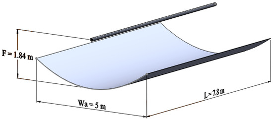
Figure 1.
The investigated LS-2 module designed in SolidWorks.
The maximum optical efficiency of this system is about 73.3%, as it is stated in References [58,59]. More specifically, the cover transmittance is selected 93.5%, the absorber absorbance 95%, and the equivalent concentrator reflectance 82.6%. It is essential to state that the equivalent reflectance includes various optical errors as tracking error, geometrical errors, and clearness factors for the concentrator and the receiver [60]. Table 1 includes all of the information about the examined PTC. The working fluid is Syltherm 800 [61], which can operate in liquid phase from −40 °C up to 400 °C.

Table 1.
Basic parameters of the examined module [58,59,60].
2.2. Basic Mathematical Formulation
2.2.1. Thermal Model
The basic mathematical equations for the development of the present model are given in Section 2.2 with details. The available solar irradiation on the collector aperture (Qs) is the product of the aperture area and the direct beam solar irradiation:
The thermal efficiency of the solar collector (ηth) is the ratio of the useful heat (Qu) to the solar irradiation (Qs):
The useful heat can (Qu) can be calculated with two ways. The first one is the energy balance on the working fluid volume.
The second way is using the heat transfer between the absorber tuber and the fluid.
The heat transfer coefficient (h) is the key parameter in this calculation. This parameter can be estimated using the Nusselt number:
Moreover, the mean fluid temperature (Tfm) is estimated as:
The thermal losses of the absorber to the cover (Qloss) are the same as the thermal losses of the cover to the ambient, because the system is considered to be in steady-state conditions. The thermal losses of the absorber to the cover can be radiation and convection thermal losses. The convection thermal losses exist only in the case of the non-evacuated tube case.
The temperature levels in Equation (7) have to be in Kelvin units. For the case of the evacuated tube collector, the (hin) is equal to zero. On the other hand, for the case of a non-evacuated tube, the inner heat transfer coefficient (hin) between the absorber and cover is calculated using the effective thermal conductivity method [62]:
The effective thermal conductivity (keff) is calculated, as below [62]:
The Prandtl number (Pr), the Rayleigh number (Ra) and the thermal conductivity (k) of the air are calculated for the mean temperature between the cover and receiver. The geometric parameter (Fg) is calculated as [62]:
The emittance of the selective cermet coating is calculated, as below [59]:
The thermal losses from the cover to the ambient are calculated as:
The temperature levels in Equation (12) have to be in Kelvin units. The heat transfer coefficient between the cover and ambient (hout) is calculated as [63,64]:
The sky temperature (Tsky) can be calculated using the following formula [65]:
The energy balance on the absorber is the most important equation of this modeling. According to this equation, the absorbed solar energy (Qabs) is separated into useful heat (Qu) and thermal losses (Qloss).
The absorbed solar energy is calculated using the optical efficiency (ηopt):
The optical efficiency is dependent on the incident angle (θ) and it is expressed using the incident angle modifier (K):
For the LS-2 module, the incident angle modifier (K) can be written as [58]:
The incident angle (θ) is in degrees for Equation (18).
2.2.2. Hydraulic Model
The calculation of the pressure drop and the pumping work is very important for the PTC evaluation. The pressure drop (ΔP) can be calculated using the friction factor (f):
The mean fluid velocity (u) is calculated as:
The pumping work demand (Wp) for the fluid movement through the absorber tube is calculated as:
2.2.3. Evaluation Criteria of the Thermal Enhancement Techniques
The thermal enhancement techniques lead to increased thermal performance and pressure drop, as it has been highlighted in Section 1. Thus, this situation has to be evaluated properly. Three different criteria are used in the pressure work for the evaluation of the flow enhancement with the simultaneous pressure drop increase, the exergy efficiency, the overall efficiency, and the performance evaluation criterion (PEC).
The exergy efficiency (ηex) evaluates the useful heat production as possible work. Also, it takes into account the pressure drop along the absorber tube. It is defined as the ratio of the useful exergy production (Eu) to the exergy flow if the solar irradiation (Es):
The useful exergy production (Eu) is calculated as [50]:
The exergy flow of the solar irradiation (Es) is calculated using the Petela model [66]:
The temperature levels in Equations (23) and (24) are in Kelvin units. The reference temperature (To) is selected at 298.15 K and the sun temperature (Tsun) at 5770 K.
The overall efficiency (ηovr) evaluates the pumping work demand as the equivalent primary energy consumption and practically gives the net useful heat production of the collector:
The electrical efficiency (ηel) is the average electrical efficiency of the grid and it takes values close to 33%. In this work, the value of 32.7% [67] is selected.
The last evaluation criterion is the performance evaluation criterion (PEC), which is a flow criterion. This index tries to evaluate the heat transfer coefficient enhancement increase under the equivalent conditions of “same pumping work demand”. Thus, the following equation is suggested for this reason [68]:
The (Nuo) and the (fo) are the Nusselt number and the friction factor of the smooth absorber case, respectively. When the (PEC) takes values over 1, then there is flow enhancement. Higher values of (PEC) indicate higher performance enhancement. The physical meaning of this parameter is the enhancement of the heat transfer coefficient (h/ho) under the same pumping work conditions between the case with the thermal enhancement method and the reference case with the smooth and empty absorber.
2.3. The Examined Thermal Enhancement Techniques
In this section, the thermal enhancement techniques of this work are presented. Equations about the Nusselt number and the friction factor are given for every case. It is important to state that the flow conditions for the present work are turbulent (Re > 2300), so the equations for turbulent flow are given.
- (a)
- Smooth case
First of all, the equations about the reference case with the smooth and empty absorber are given. For turbulent flow conditions, the Nusselt number can be written as below, using the Dittus-Boelter model [69]:
The friction factor (f) is calculated using the Moody equation [70]:
- (b)
- Internally finned absorber
Figure 2 illustrates the internally finned absorber tube. This absorber has rectangular longitudinal fins and it has been examined by Bellos et al. [39,40]. In Reference [40], equations about the Nusselt number and friction factor are given.
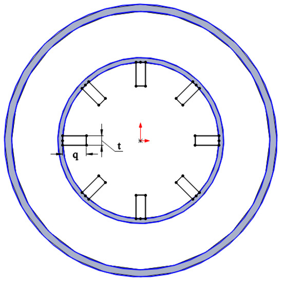
Figure 2.
Cross-section of the internally finned absorber tube.
The parameter (t) is the fin thickness and it is selected at 4 mm, while the parameter (q) is the fin length, which is selected at 15 mm in this work. These values are reliable selections, according to the results of Reference [40].
- (c)
- Twisted tape inserts
Figure 3 depicts the twisted tape insert from the study of Mwesigye et al. [13]. This insert is a usual one in the literature, and thus it is investigated in this paper. Below, equations about the Nusselt number and the friction factor are given:
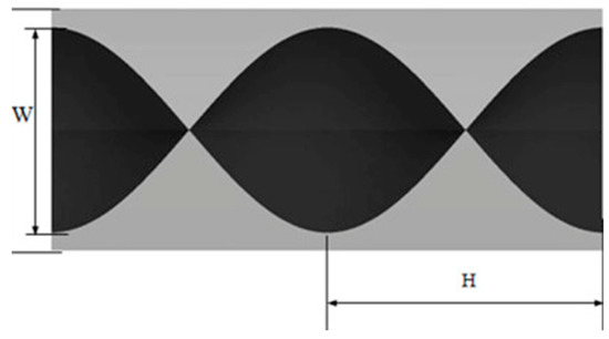
Figure 3.
The twisted tape insert from Mwesigye et al. study [13].
The parameter (H) is the twisted tape half pitch and it is selected to be 66 mm, while the parameter (W) is the twisted tape width, which is selected at 49.5 mm. These values are typical values in the suggested range of the Reference [13].
- (d)
- Perforated tape insert
Figure 4 depicts the perforated plate insert of study [24]. The Nusselt number and the friction factor about this case are given below:
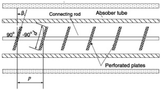
Figure 4.
Perforated plate inserts from Mwesigye et al. study [24].
The parameter p is the perforated plate spacing and it is selected at 780 mm, the parameter d is the perforated plate diameter, and it is selected at 49.5 mm, while the parameter β is the angle of the perforated plate, which is selected at zero degrees.
At the end of this section, it is important to state that the previous literature equations have been developed for PTC with thermal oil, and especially the Syltherm 800, which is the used oil for the present study. Moreover, all of these equations are valid in the examined flow conditions of this work with Reynolds numbers over 2300.
2.4. The Developed Model in EES
The present work is performed using a developed thermal model in EES. This model solves the equations of the Section 2.2 and Section 2.3, and so the collector performance is calculated under steady-state conditions. This model has been also used in References [50,51,52,53,54,55,56,57] with small modifications from study to study. Table 2 summarizes the parameters that have been selected as boundary conditions for the present problem.
Table 2.
Parameters of the present work.
The solar irradiation is selected at 1000 W/m2, while zero incident angle is selected. These values are usually in thermal studies that are focused on the thermal comparison of different ideas. The wind speed is selected at 1 m/s, which is a reasonable value according to the literature [63]. The flow rate has been select at 100 L/min, a reasonable value according to Reference [54], as well as the References [39,40,41]. The inlet temperature ranged from 50 °C to 350 °C, covering a great range of possible operating conditions.
Practically, the examined collector is investigated for different inlet temperatures, from 50 °C to 350 °C with step 25 °C, and every time one of the four absorber cases of Section 2.3 are applied. More specifically, the smooth absorber case, the internally finned absorber cases, the use of twisted tape inserts inside the absorber, and the use of perforated plate inserts inside the absorber are investigated.
These four cases are examined for both the evacuated and non-evacuated tube collector. In the case of an evacuated tube, there are no convection thermal losses between the absorber and the cover. On the other hand, for the case of a non-evacuated tube, air with 1 bar pressure is assumed to exist between cover and absorber, leading to important convection losses of the absorber.
2.5. Model Validation
This section is devoted to presenting validation evidence of the developed thermal model for both the evacuated and non-evacuated receivers. Experimental results from the study of Dudley et al. [58] are used for performing a suitable validation procedure. The investigated conditions about inlet temperature, flow rate, ambient temperature, and wind speed are used for every validation scenario, as they have been described for the experiments with cermet coating in Reference [58]. More specifically, it can be briefly stated that solar irradiation levels were close to 900 W/m2, the flow rates close to 50 L/min, the ambient temperature was around 25 °C, and there were low wind speeds of up to 3 m/s. In this work, the validation results are presented using figures in order to put the errors bars in them and to present a more suitable comparative analysis. Moreover, in every case, the mean deviation between experimental results and model is given.
The validation is conducted for the thermal efficiency and for the thermal losses. The thermal efficiency validation corresponds to real operating conditions with solar irradiation concentration. On the other hand, the thermal loss experiment is conducted with the collector being unfocused in order to check the calculation of the thermal losses.
Firstly, the validation procedure for the evacuated tube collector is given. Figure 5 depicts the thermal efficiency validation, and Figure 6, the thermal losses validation. Generally, the obtained points of the model are inside the error bars of the experiment, the fact that proves high model accuracy. The mean deviation of the thermal efficiency is 1.2% (between model and experimental results), while the mean relative experimental error of the measurements is 3.0%. The deviation of the thermal losses is 5.43 W/m2, while the mean experimental error is 6.80 W/m2. These results prove that the obtained results are acceptable and the model for the evacuated tube case is close to the experimental results and inside the error limits.
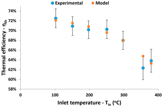
Figure 5.
Thermal efficiency validation results for the evacuated tube receiver.
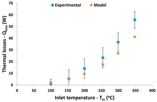
Figure 6.
Thermal losses validation results for the evacuated tube receiver.
For the non-evacuated tube case, Figure 7 and Figure 8 illustrate the validation results for the thermal efficiency and the thermal losses, respectively. The obtained results are satisfying with the model points to be generally inside the error bars of the experimental results. The mean deviation of the thermal efficiency is 2.7%, while the mean relative experimental error of the measurements is 3.1%. The deviation of the thermal losses is 2.41 W/m2, while the mean experimental error is 7.52 W/m2. These results prove that the obtained results are acceptable and that the model for the evacuated tube case is close to the experimental results and inside the error limits.
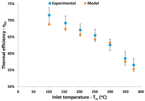
Figure 7.
Thermal efficiency validation results for the non-evacuated tube receiver.
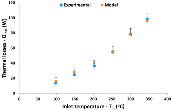
Figure 8.
Thermal losses validation results for the non-evacuated tube receiver.
So, the developed thermal model can be used both for evacuated and non-evacuated cases, and it can be characterized as reliable. All of the validations procedures are performed successfully.
3. Results and Discussion
3.1. Evacuated Tube Receiver Performance
Section 3.1 is devoted to presenting the performance results of the case with the evacuated tube collector. Figure 9 depicts the Nusselt number variation with the inlet temperature for the four examined cases. It is obvious that the use of the thermal enhancement methods leads to an increase in the Nusselt number. The highest increase is observed for the internally finned absorber and the mean Nusselt number enhancement is 135% when compared to the reference case with the smooth absorber. The use of perforated inserts is the second one case with 79% mean Nusselt number enhancement, while the use of twisted tape inserts leads to the lowest Nusselt number enhancement close to 63%. It is important to state that the enhancements are getting greater with the inlet temperature increase. Moreover, it is worthy to comment that the use of twisted tape and perforated tape inserts leads to similar results with the use of perforated tape inserts to be a better choice.
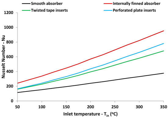
Figure 9.
Nusselt number of the examined case with evacuated tube receiver.
Figure 10 illustrates the thermal of the evacuated tube with the smooth absorber, as well as the thermal improvements with the thermal enhancement techniques. For the smooth case, the thermal efficiency is ranged from 67% to 73%, while the thermal enhancement methods lead to higher values. The best enhancement method is the use of internally finned absorber, which leads to a mean enhancement of 0.7%, while the use of perforated tape insert leads to 0.6%, and the use of twisted tape insert to 0.5%. The maximum thermal efficiency enhancements are achieved for a higher inlet temperature, because in these cases, there is higher thermal efficiency enhancement margin due to the increased thermal losses. The increased thermal losses lead to lower thermal efficiency in high temperatures, as it is proved from the results of Figure 10 for the smooth tube case.
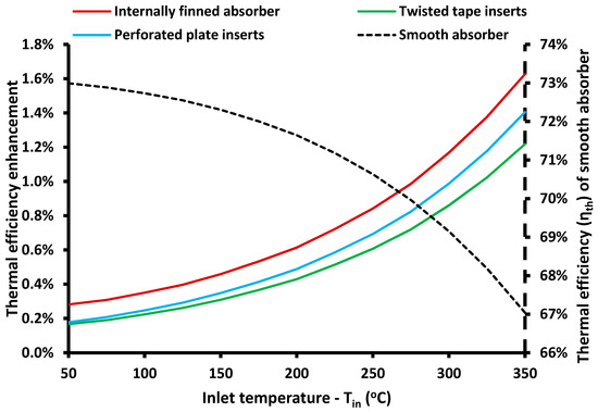
Figure 10.
Thermal efficiency of the smooth case and the thermal efficiency enhancement with the examined methods for the evacuated tube receiver.
Figure 11 shows the exergy efficiency results of the examined cases. The exergy efficiency of the smooth case has an increasing rate of the temperature increase and it reaches up to 37.9%. The increase of the inlet temperature makes the exergy factor (1 − To/Tfm) to be higher, and so the exergy efficiency has an increasing rate. However, the rate of the increase is getting lower and the curve tends to be horizontal for high temperatures. The main reason for this result is the decrease of the thermal performance, and consequently, of the useful thermal output for high temperatures. The best thermal enhancement method is again the use of internal fins with mean exergy efficiency enhancement 0.8%, while the perforated tape insert leads to 0.6%, and the twisted tape insert to 0.5%.
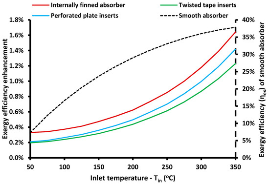
Figure 11.
Exergy efficiency of the smooth case and the thermal efficiency enhancement with the examined methods for the evacuated tube receiver.
Figure 12 exhibits the results of the overall efficiency. The overall efficiency of the smooth case ranged from 67% to 73%, and it decreases with the inlet temperature. The overall efficiency has practical the same values as the thermal efficiency, the fact that proves the extremely low impact of the pressure drop on the overall system performance. The enhancements methods aid the overall efficiency, with the mean enhancements to be 0.7%, 0.6%, and 0.5% with the use of internal fins, perforated tapes, and twisted tapes, respectively. The obtained results indicate that all of the criteria indicate the same sequence in the performance between the examined methods. Moreover, similar enhancements are observed for all of the criteria.
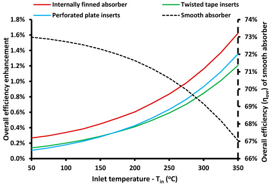
Figure 12.
Overall efficiency of the smooth case and the thermal efficiency enhancement with the examined methods for the evacuated tube receiver.
3.2. Non-Evacuated tube Receiver Performance
Section 3.2 presents the performance results for the non-evacuated tube case. In this case, there are extra convection thermal losses between the absorber and the cover, so the expected system performance is lower than the evacuated tube case (results of Section 3.1). There are important similarities between the results of Section 3.2 with the results of Section 3.1, especially in the trends of the obtained curves. Figure 13 depicts the Nusselt number for the examined cases with the non-evacuated tube. It is obvious that the obtained results are approximately the same as the results of Figure 9 for the evacuated tube case. Again, all of the thermal enhancement methods lead to Nusselt number increase when compared to the smooth case.
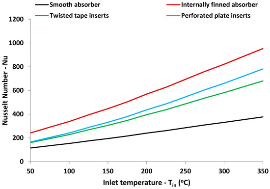
Figure 13.
Nusselt number of the examined case with non-evacuated tube receiver.
Figure 12 depicts the thermal efficiency of the non-evacuated tube case, which ranged from 71.6% to 60.7%. The mean enhancement with the internal fins is 1.3%, with perforated plate inserts 1.0% and with the twisted tape inserts being 0.9%. The enhancements have an increasing rate with the increase of the inlet temperature. Figure 13 illustrates the exergy efficiency of the non-evacuated collector that takes values up to 34.3% for the smooth case. The mean enhancements with the internal fins, the perforated tapes, and the twisted tapes are 1.4%, 1.0%, and 0.9%, respectively. Figure 14 shows the overall efficiency, which ranged from 60.7% to 71.6%. The mean enhancements with the internal fins, the perforated tapes, and the twisted tapes are 1.3%, 1.1%, and 0.9%, respectively. An interesting result of Figure 14, Figure 15 and Figure 16 is that the performance enhancement presents a high increasing rate after the inlet temperatures of 250 °C. This result is explained by the high thermal losses after this temperature limit, which makes the enhancement methods more effective.
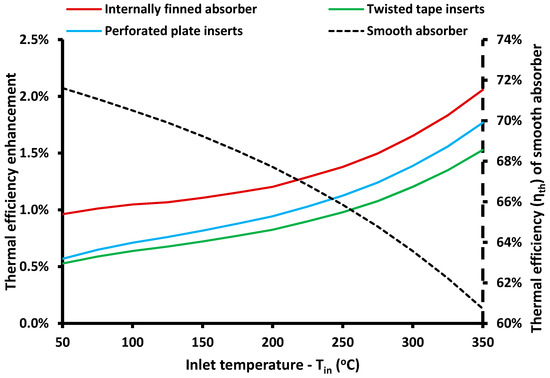
Figure 14.
Thermal efficiency of the smooth case and the thermal efficiency enhancement with the examined methods for the non-evacuated tube receiver.
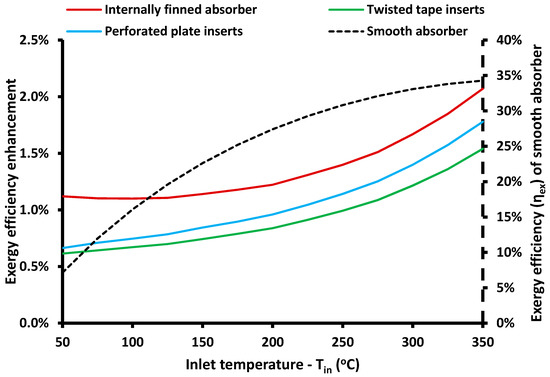
Figure 15.
Exergy efficiency of the smooth case and the exergy efficiency enhancement with the examined methods for the non-evacuated tube receiver.
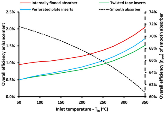
Figure 16.
Overall efficiency of the smooth case and the thermal efficiency enhancement with the examined methods for the non-evacuated tube receiver.
The obtained performance results for the non-evacuated results indicate a lower performance when compared to the evacuated tube case. More specifically, the thermal efficiency seems to be significantly lower, especially at high temperatures. For inlet temperature that is equal to 350 °C, the evacuated tube has a 67% thermal efficiency, while the non-evacuated case has 60.7%. The exergy efficiency decreases from 37.9% to 34.3%, while the overall efficiency has similar behavior to the thermal efficiency. Moreover, when comparing the enhancements of the evaluation indexes, higher enhancements are obtained for the non-evacuated cases, because in these cases, there are greater thermal losses, which is the fact that makes the performance improvement easier.
3.3. Hydraulic Performance of the Collector
The next step in this work is the hydraulic evaluation of the examined collector. The use of the thermal enhancement methods is associated with increased friction, factor, pressure drop, and pumping work, as it has been highlighted by the Section 1. Section 3.3 comes to complete this work by giving results about the friction factor, the pumping work, and the performance evaluation criterion (PEC). It is important to state that the results of Section 3.3 regarding the evacuated tube case, while they have approximately the same for the non-evacuated tube case. So, there is no reason for giving the “same” figures two times.
Figure 17 shows that the friction factor of the smooth case is the lowest among the examined cases. The use of perforated tape inserts leads to the highest friction factor, while twisted tape inserts is the second case and the internally finned absorber the third one. The mean friction factor increase with the perforated plates is 1250%, with the twisted tape inserts 370%, and with the internal fins 180%. It is obvious that the perforated plate inserts case leads to an extremely high friction factor.
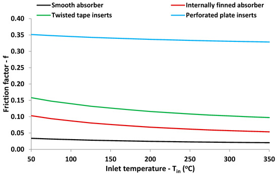
Figure 17.
Friction factor of the examined cases.
The higher friction factor leads to higher pressure drop, and consequently to higher pumping work. Figure 18 depicts the pumping work for the examined inlet temperatures. The small difference in the curves trends is explained by the influence of the density on the results, which is reduced with the temperature increase. For instance, the Syltherm 800 density is 882 kg/m3 at 80 °C, 773 kg/m3 at 200 °C, and 648 kg/m3 at 320 °C. At this point, it is important to state that the maximum pumping work is close to 8 W, while the useful heat production is about 25,000 W. So, it is obvious that the obtained pumping work is an extremely low quantity when compared to the useful heat amount. This result explained the extremely close values of thermal efficiency and overall efficiency, as they have been presented in Section 3.1 and Section 3.2.
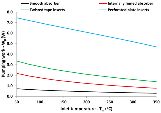
Figure 18.
Pumping work demand of the examined cases.
The last evaluation criterion is the performance evaluation criterion (PEC), which is a flow criterion. This criterion does not take into account that there are thermal losses and they are depended on the receiver temperature. It evaluates the Nusselt number enhancement and the simultaneous penalty in pressure drop. So, the values of this criterion in the solar system are not so important because it does not take into consideration the final useful yield in order to determine if the applied methods are able to enhance the overall system performance. However, this criterion has to be used for evaluating the enhancements methods and to compare them with another point of view, the flow performance view (and not the collector performance view).
Figure 19 exhibits the results about the PEC. The smooth case has (PEC = 1) and it is depicted as a horizontal line. The cases with (PEC > 1) are assumed to be enhanced, while the cases with (PEC < 1) are not enhanced. The use of internal fins leads always to values that are over 1 and from 1.4 to 1.8, results that indicate that this method leads to really flow enhancement. On the other hand, the use of perforated plate inserts leads always to value slower than 1, the fact that proves that this method does not enhance the flow. The main reason for this result is the extremely high friction factor of this method, as it has been highlighted in Figure 17. Moreover, the use of twisted tape inserts leads to the enhanced flow conditions at high temperatures (over 225 °C), because in these cases there are significant Nusselt number enhancements.
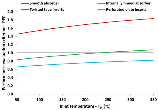
Figure 19.
Performance evaluation criterion of the examined cases.
At the end of this section, is important to state that the exergy efficiency and the overall efficiency criteria indicate that all of the method leads to performance enhancement because they evaluate the pumping work value and not the friction factor as the PEC. The exergy and the overall efficiencies are most appropriate criteria for the evaluation of the PTC because they take into account the relationships between the useful heat production and the pumping work, while the PEC takes into account flow criteria as the Nusselt number and friction factor. In other words, the PEC does not take into account whether the flow is inside a solar collector or in a tube of a heat exchanger for instance. So, it is suggested to not use the PEC as the sole criterion for the thermal enhancement methods evaluation, but to use this as a consulting criterion that has to be combined with other performance criteria as the exergy efficiency, the overall efficiency, or the entropy generation ratio criterion.
3.4. Thermal Enhancement Comparison of Evacuated and Not Evacuated Receiver
The last part of the results section is devoted to comparing the evacuated and the non-evacuated receiver with the investigated enhancement methods. Figure 20 shows the thermal efficiency enhancement with the three enhancement methods for the two receiver kinds. It is obvious that the enhancements are significantly higher for the non-evacuated tuber receiver for all of the methods. Moreover, the same sequence of the methods exists for both receivers. More specifically, the internally finned absorber enhances the performance of the non-evacuated tube up to 2.1%, while of the evacuate tube by up to 1.6%. The use of perforated plate inserts leads to an enhancement of 1.8% and 1.1% for the non-evacuated and evacuated tube, while the tested tape inserts to 1.5% and 1.2%, respectively.
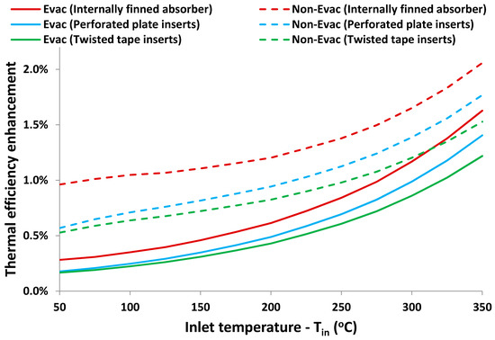
Figure 20.
Thermal efficiency enhancements with the examined methods for both the evacuated and non-evacuated tube receivers.
The reason for the higher thermal efficiency enhancement in the case of the non-evacuated tube is based on the higher thermal losses, which give a higher enhancement margin. Figure 21 depicts the thermal losses for both of the receivers, as well as the thermal loss decrease with the applied enhancement methods. It is obvious that the thermal losses with the non-evacuated tube reach up to 4940 W, while they are up to 2478 W for the evacuated tube. This result shows that the thermal losses of the evacuated tube are approximately the half when compared to the non-evacuated case. This result makes the enhancement margin to be higher in the cases of non-evacuated tube receiver. Figure 21 also shows that the thermal loss decrease with the enhancement methods is higher for the case of the non-evacuated tube. For instance, the thermal losses decrease with the internally finned tube is up to 44% for the non-evacuated tube case, and up to 31% for the evacuated tube case.
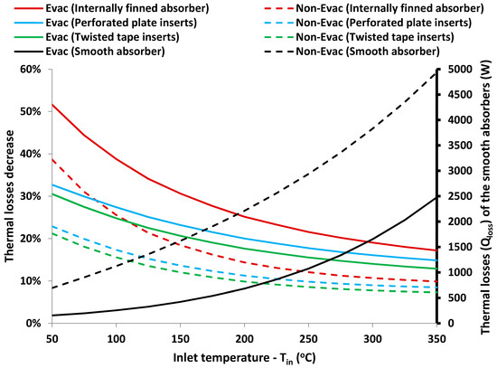
Figure 21.
Thermal losses for the smooth cases and the thermal losses enhancement with the examined methods for both the evacuated and non-evacuated tube receivers.
At the end of this analysis, it is important to state that the obtained results indicate that the thermal enhancement methods are more effective for the non-evacuated tubes than the evacuated tubes. This fact makes the use of the enhancement methods a more attractive choice for the enhancement of the performance in the non-evacuated tubes. Moreover, it can be said that, in some cases, the thermal enhancement method can be used in non-evacuated tubes in order to eliminate partially the lower performance of them compared to the evacuated tubes. However, the final selection of this design is a multi-parametric issue that is based mainly on financial parameters. Lastly, it can be said that the use of some enhancement methods can be applied in existing installation, in non-evacuated tubes that have lost their vacuum in order to enhance their performance. With this technique, the performance of the tubes with lost vacuum can be enhanced with a simple way. For instance, the use of an insert can be applied easily in the existing installations and so the non-evacuated tubes can be retrofitted. However, this idea has to be studied carefully in order to face possible operation and installation problems.
4. Conclusions
The objective of this work is to compare three usual thermal efficiency enhancement methods in parabolic trough solar collectors. The use of internally finned absorber, the use of perforated plate inserts, and the use of twisted tape inserts are investigated and compared with the reference case with the tube and empty absorber tube. The analysis is conducted both for evacuated and non-evacuated tube receivers. Typical values about the examined parameters are selected, according to the literature. The most important conclusions of this work are listed below:
- -
- All of the examined thermal efficiency enhancement methods are found to be effective and they enhance the thermal efficiency of the solar collector. Moreover, the exergy efficiency and the overall efficiency are also enhanced. The obtained enhancements are greater at higher inlet temperature levels.
- -
- The enhancements are higher for the non-evacuated tube cases, because in these cases, there are higher thermal losses and a higher thermal enhancement margin.
- -
- The highest enhancements are found with the use of internal fins, while the use of perforated inserts is the second choice and the use of twisted tape inserts leads to the lowest enhancements.
- -
- The mean thermal efficiency enhancement with the internal fins is 0.7% for the evacuated tube and 1.3% for the non-evacuated tube, while the maximum enhancements are 1.6% and 2.1%, respectively. It is important to state that these small thermal enhancements are explained by the low thermal losses of the PTC.
- -
- Furthermore, it is important to state that these small thermal enhancements are close to the possible errors from the uncertainties that are associated with the Nusselt number calculation from the used literature formula. However, there is a thermal enhancement in all of the cases, but there is uncertainty about the values of the enhancement.
- -
- The thermal enhancements methods lead to a higher friction factor and pumping work demand. The highest pressure drop was found for perforated tape inserts, while the other methods lead to lower pressure drop increases. The exergy and the overall efficiency criteria proved that the increase of the pumping work is not adequate to eliminate the thermal enhancement, and so all of the enhancement methods are effective. On the other hand, the performance evaluation criterion (PEC) showed that the use of internal fins for all the inlet temperatures and the use of twisted tape inserts for inlet temperatures over 225 °C leads to flow enhancement.
The final conclusion of this paper is that the use of the thermal enhancement method is able to increase the thermal performance of the PTC and the enhancements are higher in the non-evacuated tubes. This fact makes the combination of non-evacuated tubes with thermal enhancements methods an attractive case in order to achieve higher thermal efficiency and to design more efficient systems. Moreover, it is highlighted that the thermal enhancement methods increase the pumping work demand, but this quantity is too low in order to create limitations in the adoption of the thermal enhancement methods in the PTC.
Author Contributions
E. Bellos and C. Tzivanidis have the same contribution in all the parts of the present article.
Acknowledgments
Evangelos Bellos would like to thank “Bodossaki Foundation” for its financial support.
Conflicts of Interest
The authors declare no conflicts of interest.
Nomenclature
| A | Area | m2 |
| C | Concentration ratio | - |
| cp | Specific heat capacity under constant pressure | J/kg K |
| D | Diameter | m |
| d | Perforated plate diameter | m |
| E | Exergy rate | W |
| F | Focal distance | m |
| f | Friction factor | - |
| Fg | Geometric parameter | - |
| Gb | Solar direct beam irradiation | W/m2 |
| H | Twisted tape half pitch | m |
| h | Heat transfer coefficient of the flow | W/m2K |
| hin | Convection coefficient between absorber and cover | W/m2K |
| hout | Convection coefficient between cover and ambient | W/m2K |
| K | Incident angle modifier | - |
| keff | Effective thermal conductivity | W/mK |
| k | Thermal conductivity | W/mK |
| L | Tube length | m |
| m | Mass flow rate | kg/s |
| Nu | Nusselt number | - |
| p | Perforated plate spacing | m |
| Pr | Prandtl number | - |
| Q | Heat rate | W |
| q | Fin length | m |
| Ra | Rayleigh number | - |
| Re | Reynolds number | - |
| r | Reflectance | - |
| T | Temperature | oC or K |
| t | Fin thickness | m |
| Tsky | Sky temperature | K |
| Tsun | Sun temperature | K |
| T0 | Reference temperature | K |
| u | Fluid velocity | m/s |
| V | Volumetric flow rate | L/min |
| Vwind | Ambient air velocity | m/s |
| W | Twisted tape width | m |
| Wa | Width | m |
| Wp | Pumping work | W |
Greek Symbols
| α | Absorbance | - |
| β | Slope of the perforated plate | ° |
| ε | Emittance | - |
| ΔP | Pressure drop | Pa |
| ηel | equivalent electrical efficiency | - |
| ηex | Exergy efficiency | - |
| ηopt | Optical efficiency | - |
| ηovr | Overall efficiency | - |
| ηth | Thermal efficiency | - |
| θ | Incident angle | ° |
| μ | Dynamic viscosity | Pa s |
| ρ | Density | kg/m3 |
| σ | Stefan-Boltzmann constant | [=5.67 × 10⁻⁸ W/m2K4] |
| τ | Transmittance | - |
Subscripts and Superscripts
| a | aperture |
| air | air inside the receiver |
| am | ambient |
| c | cover |
| ci | cover inner |
| co | outer cover |
| fm | mean fluid |
| in | inlet |
| max | maximum |
| o | reference case |
| out | outlet |
| r | receiver |
| ri | inner receiver |
| ro | receiver outer |
| s | solar |
| u | useful |
Abbreviations
| EES | Engineering equation solver |
| PEC | Performance evaluation criterion |
| PTC | Parabolic trough collector |
References
- Rogada, J.R.; Barcia, L.A.; Martinez, J.A.; Menendez, M.; Juez, F.J.D. Comparative Modeling of a Parabolic Trough Collectors Solar Power Plant with MARS Models. Energies 2018, 11, 37. [Google Scholar] [CrossRef]
- Praveen, R.P.; Baseer, M.A.; Awan, A.B.; Zubair, M. Performance Analysis and Optimization of a Parabolic Trough Solar Power Plant in the Middle East Region. Energies 2018, 11, 741. [Google Scholar] [CrossRef]
- Calise, F.; Capuano, D.; Vanoli, L. Dynamic Simulation and Exergo-Economic Optimization of a Hybrid Solar-Geothermal Cogeneration Plant. Energies 2015, 8, 2606–2646. [Google Scholar] [CrossRef]
- Bellos, E.; Tzivanidis, C. Optimization of a Solar-Driven Trigeneration System with Nanofluid-Based Parabolic Trough Collectors. Energies 2017, 10, 848. [Google Scholar] [CrossRef]
- Buonomano, A.; Calise, F.; Palombo, A. Solar heating and cooling systems by absorption and adsorption chillers driven by stationary and concentrating photovoltaic/thermal solar collectors: Modelling and simulation. Renew. Sustain. Energy Rev. 2018, 82, 1874–1908. [Google Scholar] [CrossRef]
- Bellos, E.; Tzivanidis, C.; Tsimpoukis, D. Thermal, hydraulic and exergetic evaluation of a parabolic trough collector operating with thermal oil and molten salt based nanofluids. Energy Convers. Manag. 2018, 156, 388–402. [Google Scholar] [CrossRef]
- Bellos, E.; Tzivanidis, C. A review of concentrating solar thermal collectors with and without Nanofluids. J. Therm. Anal. Calorim. 2018. [Google Scholar] [CrossRef]
- Kasaeian, A.; Daneshazarian, R.; Mahian, O.; Kolsi, L.; Chamkha, A.J.; Wongwises, S.; Pop, I. Nanofluid flow and heat transfer in porous media: A review of the latest developments. Int. J. Heat Mass Transf. 2017, 107, 778–791. [Google Scholar] [CrossRef]
- Gupta, M.; Singh, V.; Kumar, R.; Said, Z. A review on thermophysical properties of nanofluids and heat transfer applications. Renew. Sustain. Energy Rev. 2017, 74, 638–670. [Google Scholar] [CrossRef]
- Bhakta, A.K.; Panday, N.K.; Singh, S.N. Performance Study of a Cylindrical Parabolic Concentrating Solar Water Heater with Nail Type Twisted Tape Inserts in the Copper Absorber Tube. Energies 2018, 11, 204. [Google Scholar] [CrossRef]
- Too, Y.C.S.; Benito, R. Enhancing heat transfer in air tubular absorbers for concentrated solar thermal applications. Appl. Therm. Eng. 2013, 50, 1076–1083. [Google Scholar] [CrossRef]
- Jaramillo, O.A.; Borunda, M.; Velazquez-Lucho, K.M.; Robles, M. Parabolic trough solar collector for low enthalpy processes: An analysis of the efficiency enhancement by using twisted tape inserts. Renew. Energy 2016, 93, 125–141. [Google Scholar] [CrossRef]
- Mwesigye, A.; Bello-Ochende, T.; Meyer, J.P. Heat transfer and entropy generation in a parabolic trough receiver with wall-detached twisted tape inserts. Int. J. Therm. Sci. 2016, 99, 238–257. [Google Scholar] [CrossRef]
- Ghadirijafarbeigloo, S.H.; Zamzamian, A.H.; Yaghoubi, M. 3-D Numerical Simulation of Heat Transfer and Turbulent Flow in a Receiver Tube of Solar Parabolic Trough Concentrator with Louvered Twisted-tape Inserts. Energy Procedia 2014, 49, 373–380. [Google Scholar] [CrossRef]
- Zhu, X.; Zhu, L.; Zhao, J. Wavy-tape insert designed for managing highly concentrated solar energy on absorber tube of parabolic trough receiver. Energy 2017. [Google Scholar] [CrossRef]
- Chang, C.; Xu, C.; Wu, Z.Y.; Li, X.; Zhang, Q.Q.; Wang, Z.F. Heat Transfer Enhancement and Performance of Solar Thermal Absorber Tubes with Circumferentially Non-uniform Heat Flux. Energy Procedia 2015, 69, 320–327. [Google Scholar] [CrossRef]
- Rawani, A.; Sharma, S.P.; Singh, K.D.P. Enhancement in Performance of Parabolic Trough Collector with Serrated Twisted-tape Inserts. Int. J. Thermodyn. 2017, 20, 111–119. [Google Scholar] [CrossRef]
- Liu, Y.; Chen, Q.; Hu, K.; Hao, J.-H. Flow field optimization for the solar parabolic trough receivers in direct steam generation systems by the variational principle. Int. J. Heat Mass Transf. 2016, 102, 1073–1081. [Google Scholar] [CrossRef]
- Song, X.; Dong, G.; Gao, F.; Diao, X.; Zheng, L.; Zhou, F. A numerical study of parabolic trough receiver with nonuniform heat flux and helical screw-tape inserts. Energy 2014, 77, 771–782. [Google Scholar] [CrossRef]
- Diwan, K.; Soni, M.S. Heat Transfer Enhancement in Absorber Tube of Parabolic Trough Concentrators Using Wire-Coils Inserts. Univers. J. Mech. Eng. 2015, 3, 107–112. [Google Scholar] [CrossRef]
- Şahin, H.M.; Baysal, E.; Dal, A.R.; Şahin, N. Investigation of heat transfer enhancement in a new type heat exchanger using solar parabolic trough systems. Int. J. Hydrog. Energy 2015, 40, 15254–15266. [Google Scholar] [CrossRef]
- Jamal-Abad, M.T.; Saedodin, S.; Aminy, M. Experimental investigation on a solar parabolic trough collector for absorber tube filled with porous media. Renew. Energy 2017, 107, 156–163. [Google Scholar] [CrossRef]
- Wang, P.; Liu, D.Y.; Xu, C. Numerical study of heat transfer enhancement in the receiver tube of direct steam generation with parabolic trough by inserting metal foams. Appl. Energy 2013, 102, 449–460. [Google Scholar] [CrossRef]
- Mwesigye, A.; Bello-Ochende, T.; Meyer, J.P. Heat transfer and thermodynamic performance of a parabolic trough receiver with centrally placed perforated plate inserts. Appl. Energy 2014, 136, 989–1003. [Google Scholar] [CrossRef]
- Mwesigye, A.; Bello-Ochende, T.; Meyer, J.P. Multi-objective and thermodynamic optimisation of a parabolic trough receiver with perforated plate inserts. Appl. Therm. Eng. 2015, 77, 42–56. [Google Scholar] [CrossRef]
- Chang, C.; Sciacovelli, A.; Wu, Z.; Li, X.; Li, Y.; Zhao, M.; Deng, J.; Wang, Z.; Ding, Y. Enhanced heat transfer in a parabolic trough solar receiver by inserting rods and using molten salt as heat transfer fluid. Appl. Energy 2018, 220, 337–350. [Google Scholar] [CrossRef]
- Ghasemi, S.E.; Ranjbar, A.A. Numerical thermal study on effect of porous rings on performance of solar parabolic trough collector. Appl. Therm. Eng. 2017, 118, 807–816. [Google Scholar] [CrossRef]
- Kumar, K.R.; Reddy, K.S. Thermal analysis of solar parabolic trough with porous disc receiver. Appl. Energy 2009, 86, 1804–1812. [Google Scholar] [CrossRef]
- Reddy, K.S.; Kumar, K.R.; Ajay, C.S. Experimental investigation of porous disc enhanced receiver for solar parabolic trough collector. Renew. Energy 2015, 77, 308–319. [Google Scholar] [CrossRef]
- Kumar, K.R.; Reddy, K.S. Effect of porous disc receiver configurations on performance of solar parabolic trough concentrator. Heat Mass Transf. 2012, 48, 555–571. [Google Scholar] [CrossRef]
- Zheng, Z.; Xu, Y.; He, Y.-L. Thermal analysis of a solar parabolic trough receiver tube with porous insert optimized by coupling genetic algorithm and CFD. Sci. China Tech. Sci. 2016, 59, 1475–1485. [Google Scholar] [CrossRef]
- Cheng, Z.D.; He, Y.L.; Cui, F.Q. Numerical study of heat transfer enhancement by unilateral longitudinal vortex generators inside parabolic trough solar receivers. Int. J. Heat Mass Transf. 2012, 55, 5631–5641. [Google Scholar] [CrossRef]
- Gong, X.; Wang, F.; Wang, H.; Tan, J.; Lai, Q.; Han, H. Heat transfer enhancement analysis of tube receiver for parabolic trough solar collector with pin fin arrays inserting. Solar Energy 2017, 144, 185–202. [Google Scholar] [CrossRef]
- Benabderrahmane, A.; Aminallah, M.; Laouedj, S.; Benazza, A.; Solano, J.P. Heat Transfer Enhancement in a Parabolic Trough Solar Receiver using Longitudinal Fins and Nanofluids. J. Therm. Sci. 2016, 25, 410–417. [Google Scholar]
- Reddy, K.S.; Satyanarayana, G.V. Numerical Study of Porous Finned Receiver for Solar Parabolic Trough Concentrator. Eng. Appl. Comput. Fluid Mech. 2008, 2, 172–184. [Google Scholar] [CrossRef]
- Bellos, E.; Tzivanidis, C.; Daniil, I.; Antonopoulos, K.A. The impact of internal longitudinal fins in parabolic trough collectors operating with gases. Energy Convers. Manag. 2017, 135, 35–54. [Google Scholar] [CrossRef]
- Bellos, E.; Tzivanidis, C.; Daniil, I. Energetic and exergetic investigation of a parabolic trough collector with internal fins operating with carbon dioxide. Int. J. Energy Environ. Eng. 2017, 8, 109–122. [Google Scholar] [CrossRef]
- Bellos, E.; Tzivanidis, C.; Daniil, I. Thermal and exergetic evaluation of parabolic trough collectors with finned absorbers operating with air. Proc. Inst. Mech. Eng. Part J. Power Energy 2017. [Google Scholar] [CrossRef]
- Bellos, E.; Tzivanidis, C.; Tsimpoukis, D. Thermal enhancement of parabolic trough collector with internally finned absorbers. Solar Energy 2017, 157, 514–531. [Google Scholar] [CrossRef]
- Bellos, E.; Tzivanidis, C.; Tsimpoukis, D. Multi-criteria evaluation of parabolic trough collector with internally finned absorbers. Appl. Energy 2017, 205, 540–561. [Google Scholar] [CrossRef]
- Bellos, E.; Tzivanidis, C.; Tsimpoukis, D. Optimum number of internal fins in parabolic trough collectors. Appl. Therm. Eng. 2018, 137, 669–677. [Google Scholar] [CrossRef]
- Muñoz, J.; Abánades, A. A technical note on application of internally finned tubes in solar parabolic trough absorber pipes. Solar Energy 2011, 85, 609–612. [Google Scholar] [CrossRef]
- Muñoz, J.; Abánades, A. Analysis of internal helically finned tubes for parabolic trough design by CFD tools. Appl. Energy 2011, 88, 4139–4149. [Google Scholar] [CrossRef]
- Wang, F.; Tang, Z.; Gong, X.; Tan, J.; Han, H.; Li, B. Heat transfer performance enhancement and thermal strain restrain of tube receiver for parabolic trough solar collector by using asymmetric outward convex corrugated tube. Energy 2016, 114, 275–292. [Google Scholar]
- Huang, Z.; Li, Z.-Y.; Yu, G.-L.; Tao, W.-Q. Numerical investigations on fully-developed mixed turbulent convection in dimpled parabolic trough receiver tubes. Appl. Therm. Eng. 2017, 114, 1287–1299. [Google Scholar] [CrossRef]
- Bitam, E.W.; Demagh, Y.; Hachicha, A.A.; Benmoussa, H.; Kabar, Y. Numerical investigation of a novel sinusoidal tube receiver for parabolic trough technology. Appl. Energy 2018, 218, 494–510. [Google Scholar] [CrossRef]
- Bellos, E.; Tzivanidis, C.; Antonopoulos, K.A.; Gkinis, G. Thermal enhancement of solar parabolic trough collectors by using nanofluids and converging-diverging absorber tube. Renew. Energy 2016, 94, 213–222. [Google Scholar] [CrossRef]
- Huang, Z.; Yu, G.L.; Li, Z.Y.; Tao, W.Q. Numerical study on heat transfer enhancement in a receiver tube of parabolic trough solar collector with dimples, protrusions and helical fins. Energy Procedia 2015, 69, 1306–1316. [Google Scholar] [CrossRef]
- F-Chart Software, Engineering Equation Solver (EES), 2015. Available online: http://www.fchart.com/ees (accessed on 1 February 2018).
- Bellos, E.; Tzivanidis, C.; Antonopoulos, K.A. A detailed working fluid investigation for solar parabolic trough collectors. Appl. Therm. Eng. 2017, 114, 374–386. [Google Scholar] [CrossRef]
- Bellos, E.; Tzivanidis, C. A detailed exergetic analysis of parabolic trough collectors. Energy Convers. Manag. 2017, 149, 275–292. [Google Scholar] [CrossRef]
- Bellos, E.; Tzivanidis, C.; Antonopoulos, K.A.; Daniil, I. The use of gas working fluids in parabolic trough collectors—An energetic and exergetic analysis. Appl. Therm. Eng. 2016, 109, 1–14. [Google Scholar] [CrossRef]
- Bellos, E.; Tzivanidis, C. Thermal efficiency enhancement of nanofluid-based parabolic trough collectors. J. Therm. Anal. Calorim. 2018. [Google Scholar] [CrossRef]
- Bellos, E.; Tzivanidis, C. Assessment of the thermal enhancement methods in parabolic trough collectors. Int. J. Energy Environ. Eng. 2017, 9, 59–70. [Google Scholar] [CrossRef]
- Bellos, E.; Tzivanidis, C. Thermal analysis of parabolic trough collector operating with mono and hybrid nanofluids. Sustain. Energy Technol. Assess. 2018, 26, 105–115. [Google Scholar] [CrossRef]
- Bellos, E.; Tzivanidis, C. Parametric investigation of supercritical carbon dioxide utilization in parabolic trough collectors. Appl. Therm. Eng. 2017, 127, 736–747. [Google Scholar] [CrossRef]
- Bellos, E.; Tzivanidis, C. Parametric investigation of nanofluids utilization in parabolic trough collectors. Therm. Sci. Eng. Progress 2017, 2, 71–79. [Google Scholar] [CrossRef]
- Dudley, V.; Kolb, G.; Sloan, M.; Kearney, D. SEGS LS2 solar collector-test results. In Report of Sandia National Laboratories; SAN94-1884; Philogiston Press: Cambridge, MA, USA, 1994. [Google Scholar]
- Forristall, R. Heat Transfer Analysis and Modeling of a Parabolic trough Solar Receiver Implemented in Engineering Equation Solver; National Renewable Energy Laboratory (NREL): Golden, CO, USA; Springfield, VA, USA, 2003.
- Behar, O.; Khellaf, A.; Mohammedi, K. A novel parabolic trough solar collector model—Validation with experimental data and comparison to Engineering Equation Solver (EES). Energy Convers. Manag. 2015, 106, 268–281. [Google Scholar] [CrossRef]
- Available online: https://www.loikitsdistribution.com/files/syltherm-800-technical-data-sheet.pdf (accessed on 1 February 2018).
- Raithby, G.D.; Hollands, K. A general method of obtaining approximate solutions to laminar and turbulent free convection problems. Adv. Heat Transf. 1975, 11, 265–315. [Google Scholar]
- Qiu, Y.; Li, M.-J.; He, Y.-L.; Tao, W.-Q. Thermal performance analysis of a parabolic trough solar collector using supercritical CO2 as heat transfer fluid under non-uniform solar flux. Appl. Therm. Eng. 2017, 115, 1255–1265. [Google Scholar] [CrossRef]
- Bhowmik, N.C.; Mullick, S.C. Calculation of tubular absorber heat loss factor. Solar Energy 1985, 35, 219–225. [Google Scholar] [CrossRef]
- Swinbank, W.C. Long-wave radiation from clear skies. QJR Meteorol. Soc. 1963, 89, 339–340. [Google Scholar] [CrossRef]
- Petela, R. Exergy of undiluted thermal radiation. Solar Energy 2003, 74, 469–488. [Google Scholar] [CrossRef]
- Wirz, M.; Petit, J.; Haselbacher, A.; Steinfeld, A. Potential improvements in the optical and thermal efficiencies of parabolic trough concentrators. Solar Energy 2014, 107, 398–414. [Google Scholar] [CrossRef]
- Hasanpour, A.; Farhadi, M.; Sedighi, K. A review study on twisted tape inserts on turbulent flow heat exchangers: The overall enhancement ratio criteria. Int. Commun. Heat Mass Transf. 2014, 55, 53–62. [Google Scholar] [CrossRef]
- Leinhard, J., IV; Leinhard, J., V. A Heat Tranfer Textbook, 4th ed.; Philogiston Press: Cambridge, MA, USA, 2012. [Google Scholar]
- Moody, L.F. Friction factors for pipe flow. Trans. ASME 1944, 66, 671–684. [Google Scholar]


© 2018 by the authors. Licensee MDPI, Basel, Switzerland. This article is an open access article distributed under the terms and conditions of the Creative Commons Attribution (CC BY) license (http://creativecommons.org/licenses/by/4.0/).