3.1. Electromagnetic Design of the High Speed BLDCM
For this BLDCM, the PM is magnetized in parallel with two poles for high energy density and well sine wave of air-gap flux density [
19]. The BLDCM is designed for rated power 30 kW with highest speed 60,000 rpm. For coordinating electromagnetic and mechanical performance, the outer diameter and thickness of PM, and the outer diameter of rotor are set as dynamic variables, namely, key sizes left to determine in
Section 3.3 and
Section 3.4.
After initial design via Formula (1) for BLDCM [
11], diameters and length of motor stator are set. Three dynamic variables left as
Table 1 shows and they are to be solved with MB design and mechanical design in the following Parts.
With losses calculated by (4) and (5), the initial design parameters are defined as
Table 1 shows. They are set as design interface for MBs design, rotor design, and thermal design, to coordinate various requirements interactively.
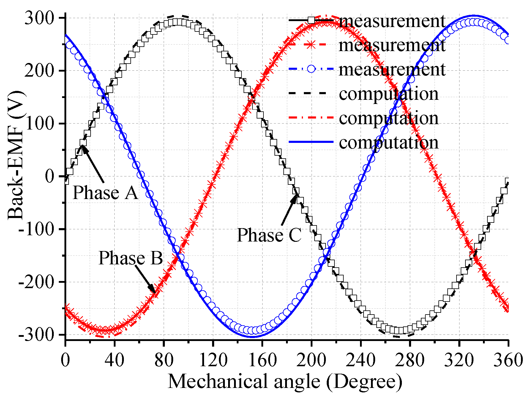
Back-EMF (electro-motive-force) of BLDCM Vemf, related to flux density and angular speed, is calculated by [
30]:
B is the flux density analyzed by electromagnetic equations of BLDCM. The maximum value of
B is calculated as 0.35 T. The result of back-EMF coefficients are 0.0677 Vs/rad, which would be validated via deceleration EMF test in
Section 4.1. The general solutions for back-EMF and the flux density distribution in air-gap are introduced in [
31] in detail. Then, electromagnetic field equation is modeled. In addition the eddy current expression, including varieties of harmonic components penetrating into the whole surface of the rotor, can be deduced from equivalent current sheet [
31]. Thus, based on the Poynting vector theory, the corresponding average electromagnetic power loss in rotor is given by [
27]:
Because of obvious influence on eddy current loss (ECL) exerted by outer diameter of rotor and slot notch width, these two variables are set as dynamic variables. They are to be solved by means of mechanical and thermal analysis in following parts, jointly.
Besides, core loss in stator can be calculated via [
32]:
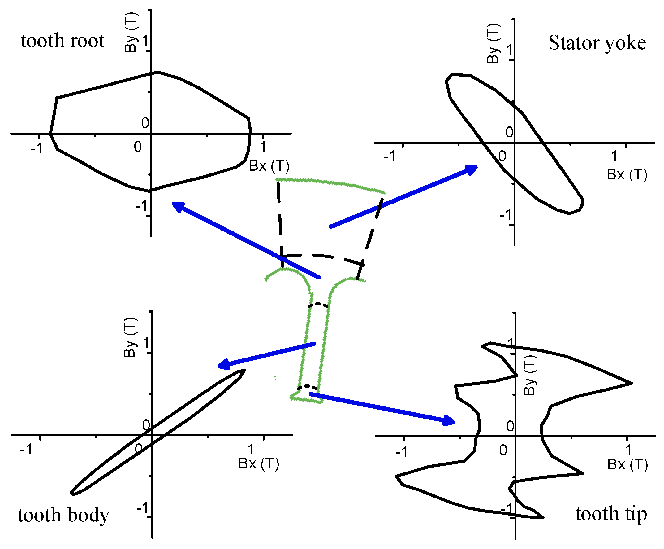
The stator is divided into several subdomains, such as yoke and tooth, to get flux discs, as
Figure 5 shows. Then
Bkmax and
Bkmin are obtained via Elliptic Fourier operator on each elliptic loci of flux discs shown in
Figure 5 by algorithm.
Since size of yoke like outer diameter has been determined in initial design via Formula (1), the slot sizes are determined here via core loss by (5).
Kh,
Kc,
Ke, varying by frequency of excitation current and thickness of lamination, are got by BP fitting method as
Table 2 shows.
In
Table 2, the steel lamination made of 20WTG with 0.2 mm thickness is adopted, whose
α = 1.62 in low frequency. By means of the Formula (4) and (5), and core loss coefficients in
Table 2, the ECL and core loss can be calculated, which is used for estimate efficiency and thermal heat source.
Based on above calculation, as
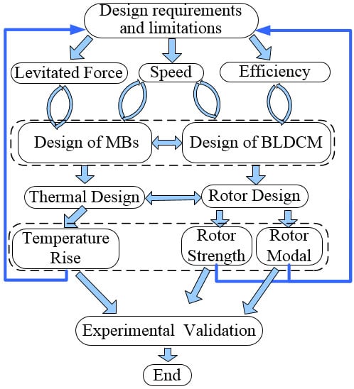
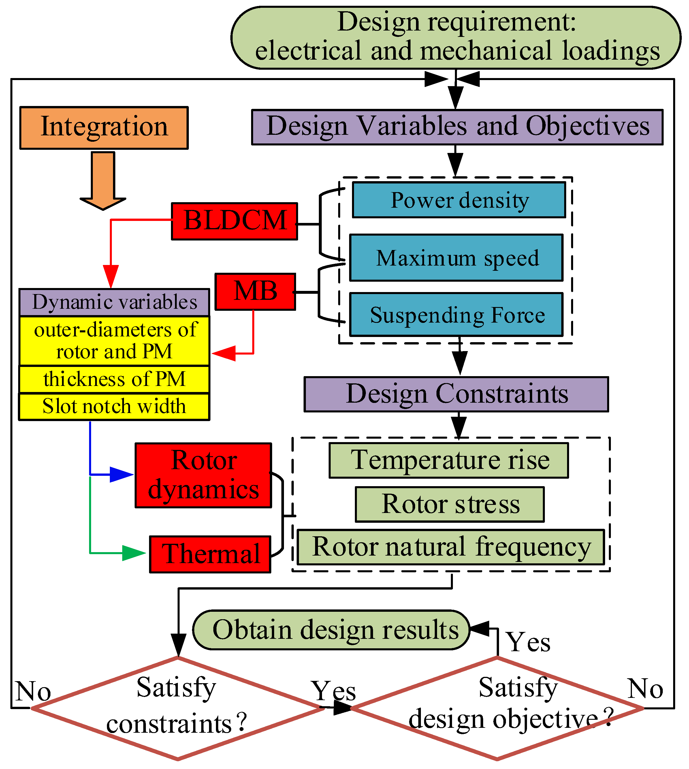
Table 3 shows, the ECL is 289 W, and the core loss is 187 W when the machine operates at 48,000 rpm. The loss values are set as the design interfaces for thermal design, because losses are heat source for thermal calculation and simulation. Temperature rise of motor got by thermal analysis completes the design loop to improve the integration design procedure (which has been shown in
Figure 2).
In
Table 4,
x9 is left as dynamic variable, for it affects ECL obviously, so which is to be solved after thermal analysis.
3.2. Electromagnetic Design of the MBs
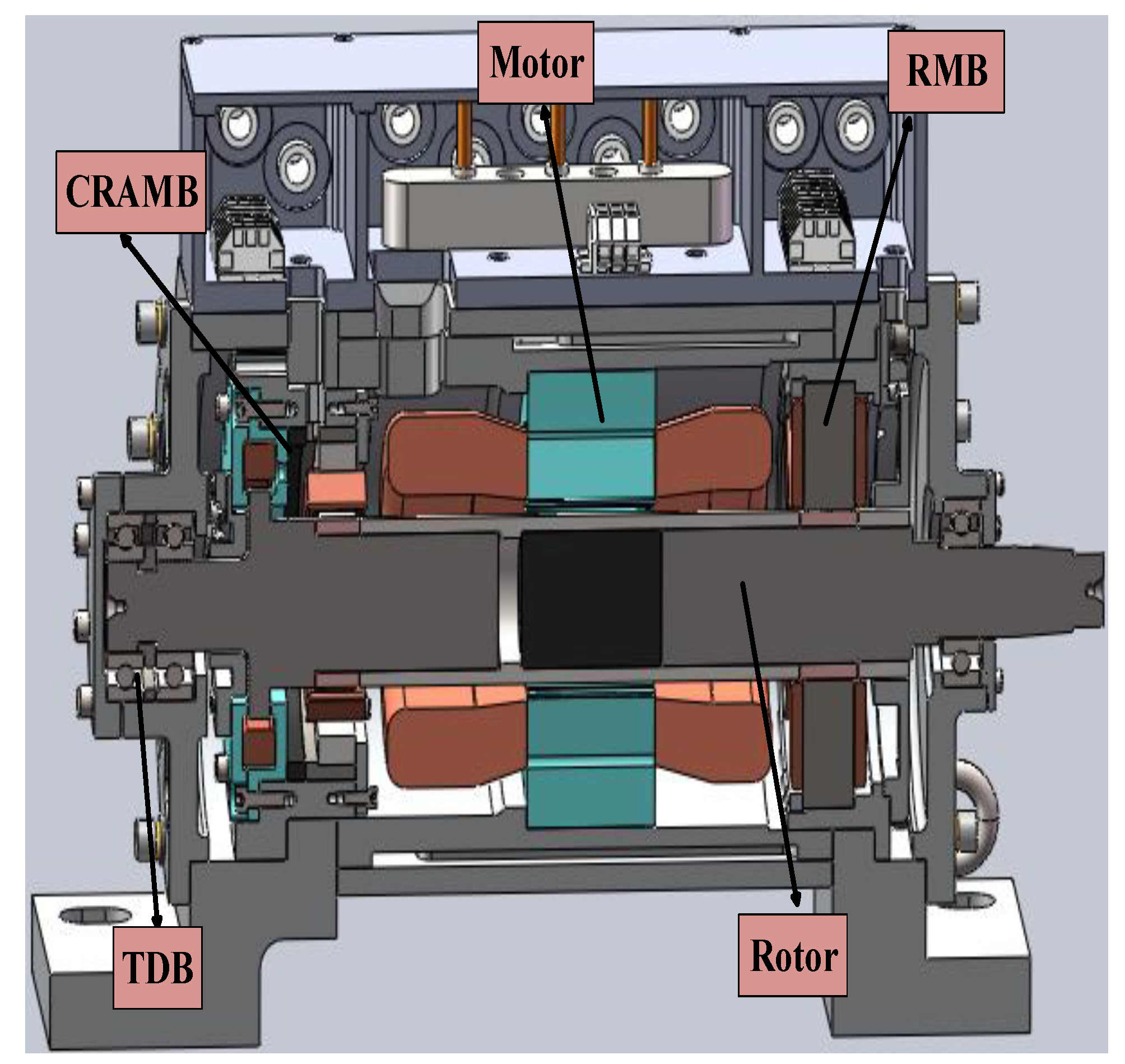
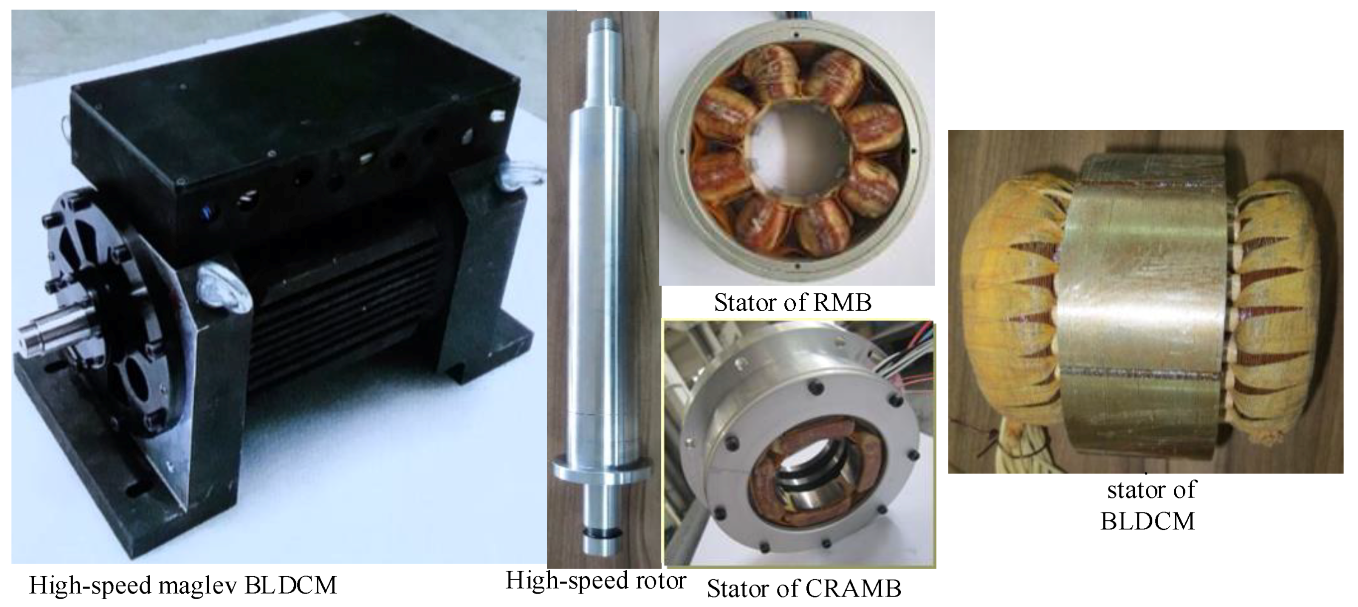
The actively controlled RMB and CRAMB are proposed for reducing power consumption, decreasing weight, increasing power density, and making dynamic performance of the rotor more robust reliability and active controllability.
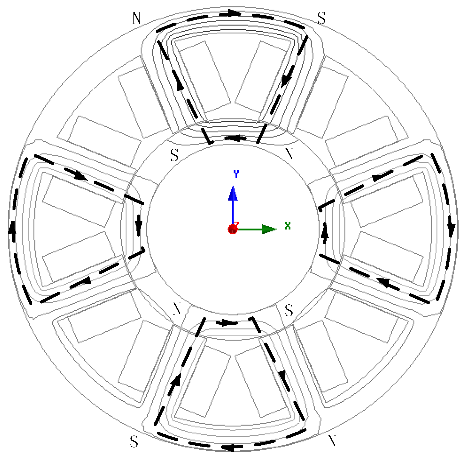
The RMB with electromagnetic bias is adopted. For control performance, the RMB stator consists of soft magnetic laminations with eight poles and coils spaced equally, of which two of them are comprised for one positive or negative direction pole in series. The RMB’s magnetic flux path and configuration are shown in
Figure 6 [
23,
24,
25]. The design model is established, as Formula (2) shows, based on that magnetic flux model, with design parameters shown as
Table 5.
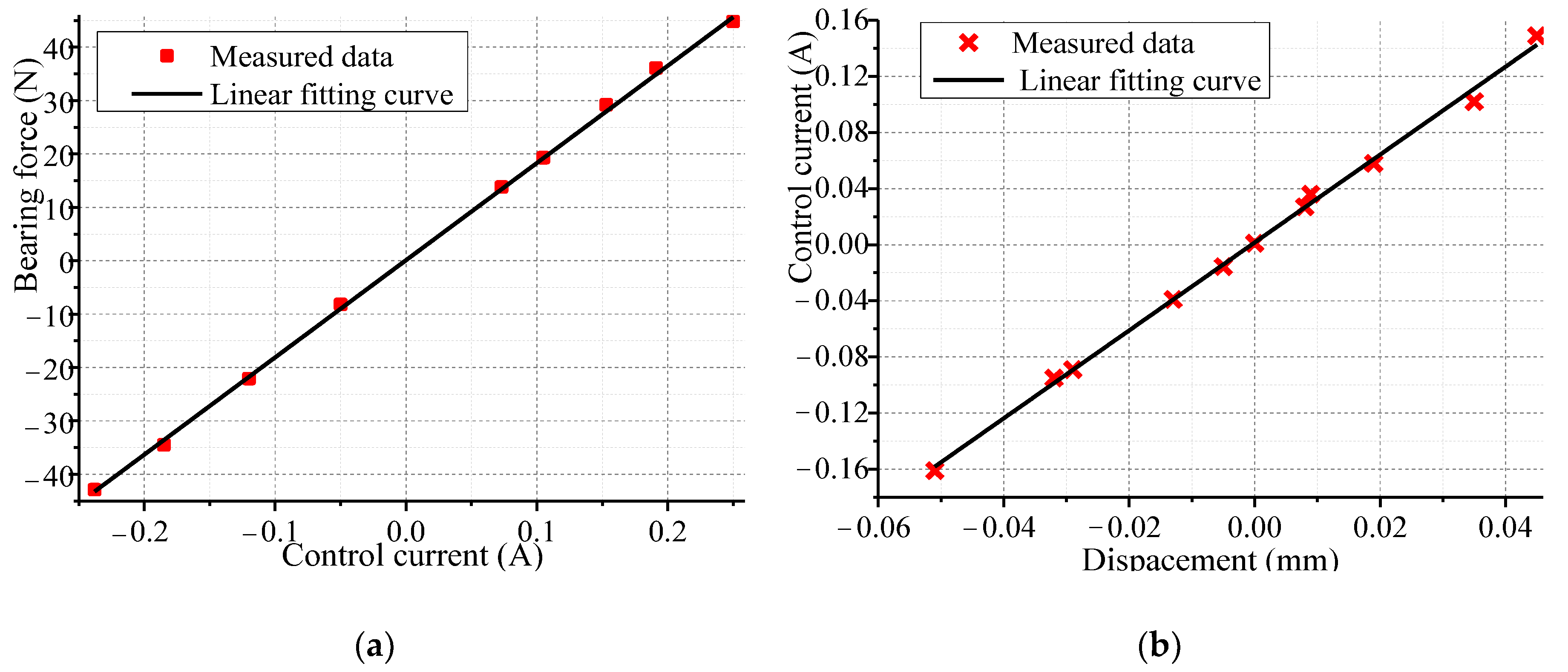
The simplified expression of radial force of RMB is obtained after its nonlinear terms over second order are neglected. Besides, this principle has also been applied for deduction of magnetic force of CRAMB in the followings. As a result, the total magnetic radial levitated force can be got by Formula (2), which is deduced from (6). Calculation values of current stiffness and position stiffness at rotor center position are 180 N/A and 587.1 N/mm respectively. They are to be validated by stiffness experiment in
Section 4.2 to form a complete closed design loop for whole design procedure.
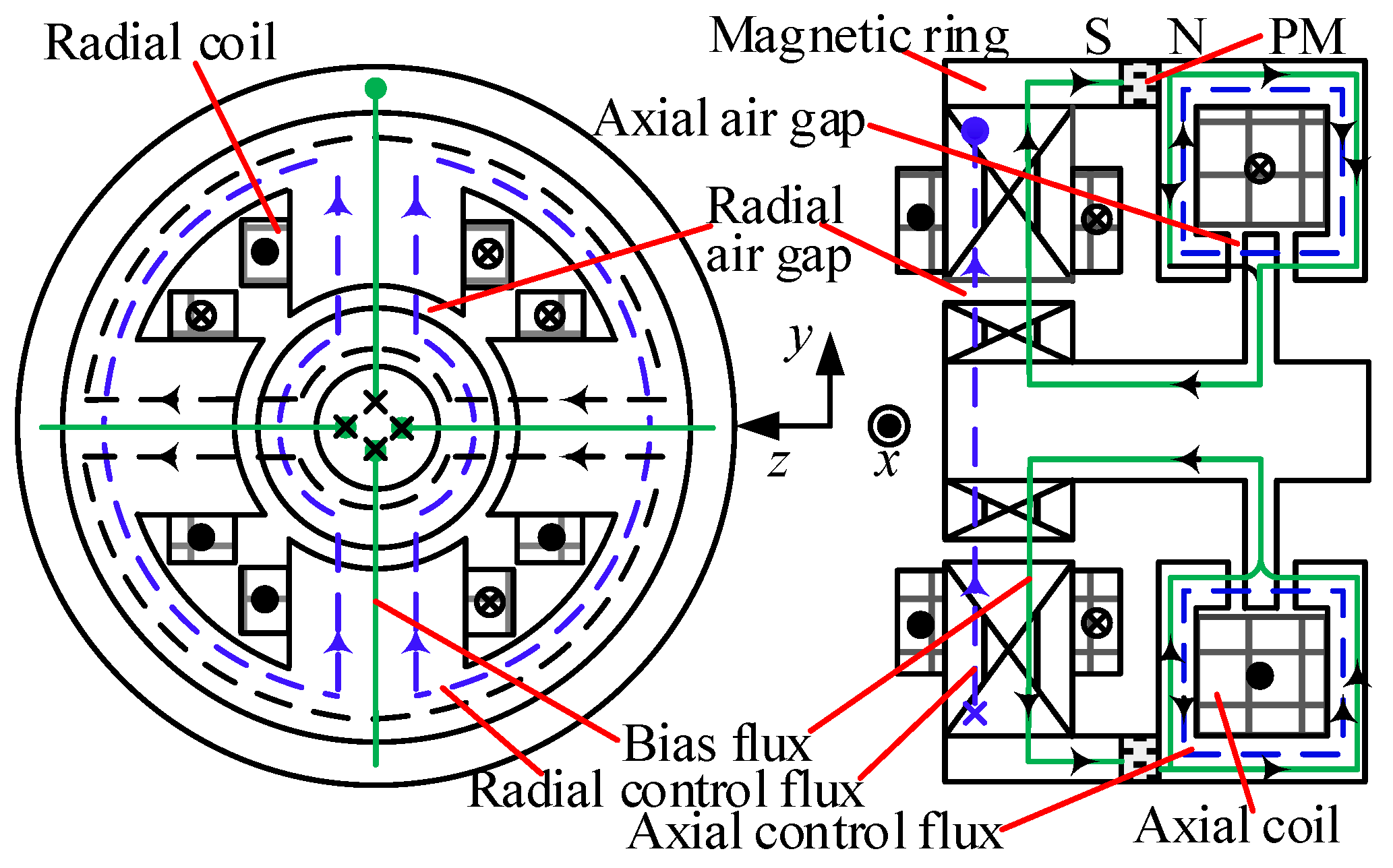
A CRAMB is proposed in this paper for its small thrust disk and axial size, and low wind friction power consumption.
Figure 7 illustrates the configuration and flux paths in CRAMB. It consists of RMB and thrust MB (TMB) units. Radial coils and axial coils generate control flux (indicated as blue dotted line), while the PM provides bias flux (indicated as green line). The similar structure of this CRAMB has been presented and analyzed in [
21]. Its RMB unit is also designed by (2). Design parameters of CRAMB are shown in
Table 6.
Magnetic forces of CRAMB in radial and axial direction are all deduced base on the following formula [
23,
24,
25]:
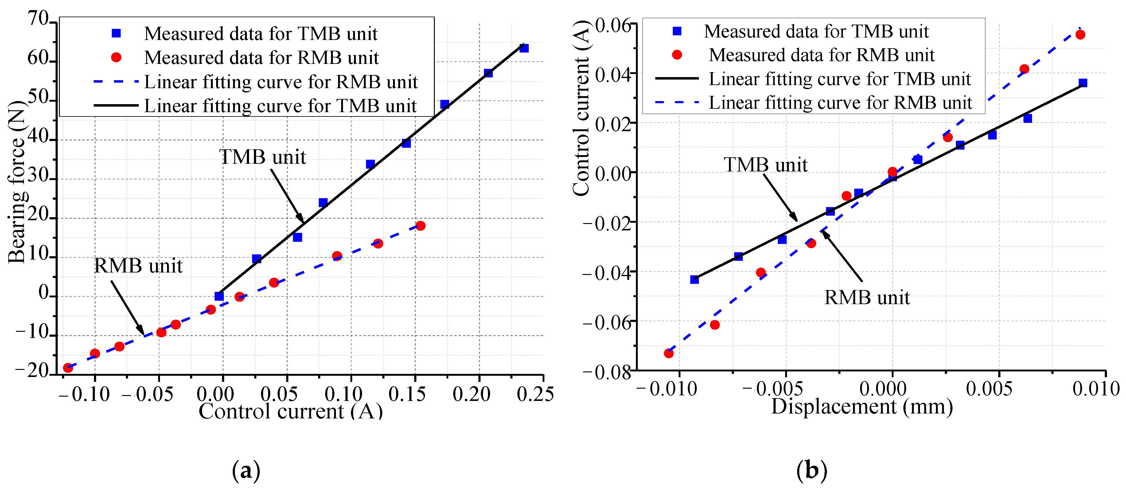
Obtained by relationships that the bearing force varied by coil currents and rotor displacement for RMB and TMB units of the CRAMB respectively via FEM, the predicted current stiffness and displacement stiffness of the RMB unit at rotor center position are 137.3 N/A and −692 N/mm respectively. The predicted current stiffness and displacement stiffness of the TMB unit at rotor center position are 261.5 N/A and −1086 N/mm, respectively, validated by experiment. For rotor weight less than 8 kg, aforementioned current stiffness value promises that the rotor can be levitated fast and stably.
3.3. Design of High Speed Rotor Considering Its Dynamics
Since high speed rotor is crucial part of high speed machine, the stress or strength limitation is influenced by materials and craftwork of the assembly of rotor enormously and inherently. And rotor mode limitation should be considered here. For active vibration control of rotor, the first order bending mode frequency of this high speed rotor should exist far from the operating frequency (60,000 rpm) for stable rotation.
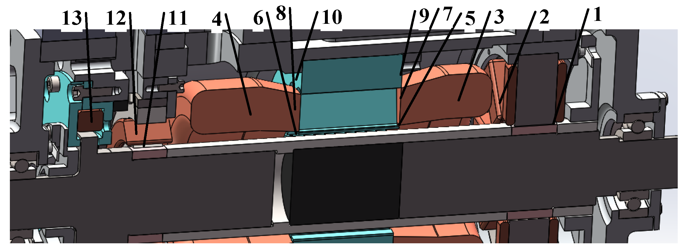
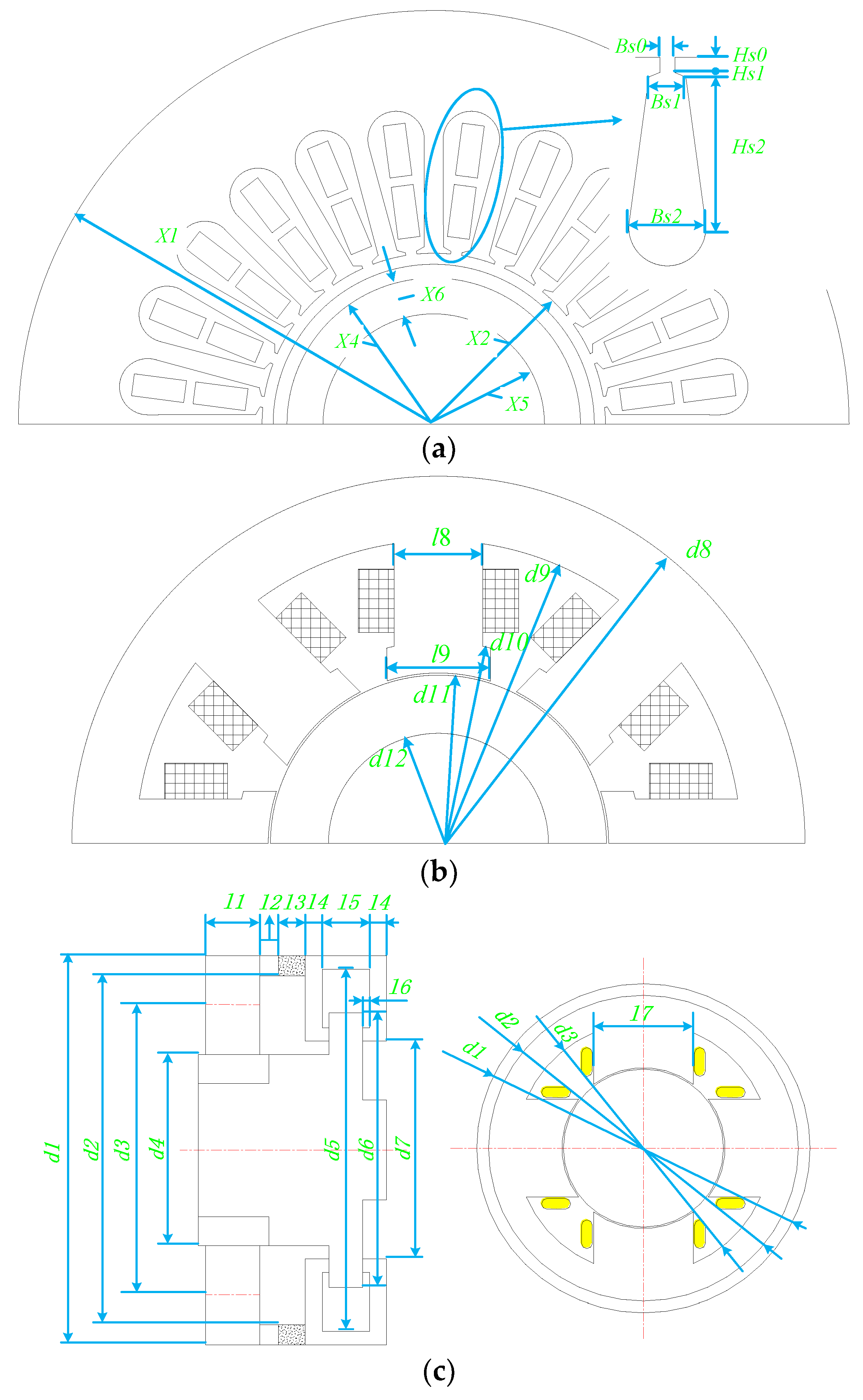
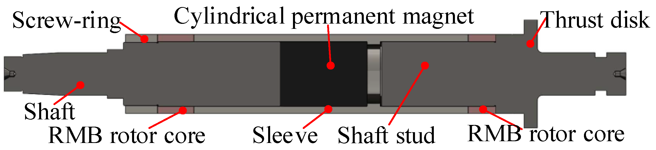
The configuration of this maglev high speed rotor is shown in
Figure 8 in this work, and the material of every part in it is listed in
Table 7. A pre-compressive stress is applied on the permanent magnet, by using an interference fit with sleeve to reduce the tensile stress against high speed centrifugal force. Total equivalent stress must be restricted below the yielding point of rotor assembly material throughout the whole speed range. The value of interference fit is 0.18 mm, which is adopted between the cylindrical rotor parts and the sleeve.
After the rotor is scattered into many finite units, the rotor mode can be calculated based on vibration equation:
Solution existence condition of
ωr is that the determinant of displacement impedance matrix as
Z is 0, that is:
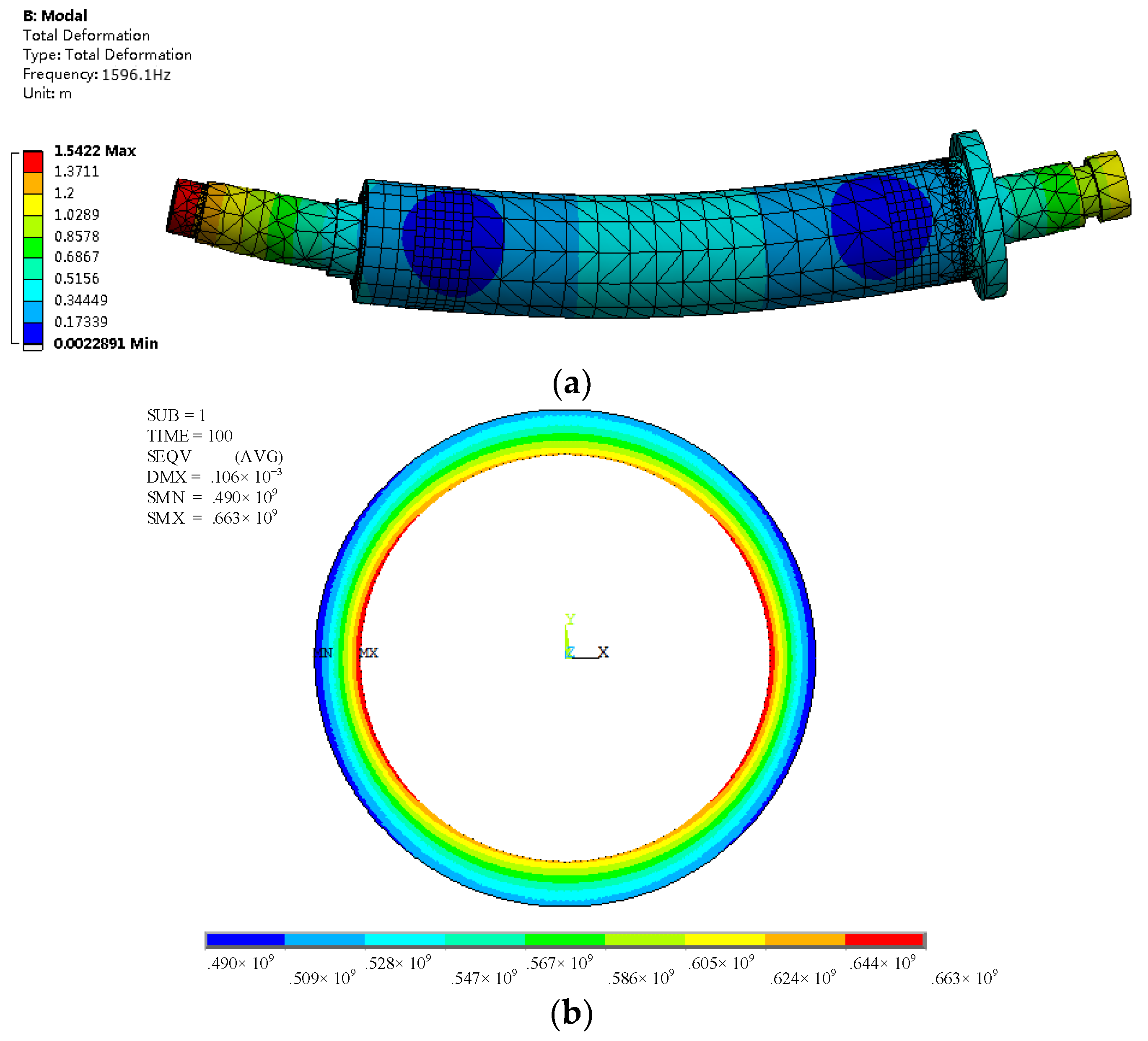
While the mr, cr and kr are all positive definite matrixes, eigenvalues of it λi2 can be solved, of which λi is mode. First order bending mode is calculated by transfer matrix method to determine initial rotor with stress analysis together. FEM results of first-order bending mode is used to validate the effectiveness of above analytical model. The CAD model of rotor assembly is imported into ANSYS simulation interface for rotor modal, then mesh and solution of FEM model are completed. Its first-order bending mode is 1596 Hz calculated by FEM, while the tested result is 1590.7 Hz by an excitation method (flexible free suspension of rotor), where error is less than 1%. Besides, the deviation between the inertial spindle and rotating spindle is very small because of the better off-line and on-line dynamic balance operation, so the eccentricity led by rotor unbalance can be neglected, which has been validated by experiment.
The equivalent Mise stress of rotor is calculated based on Von-Mises yield criterion. The crucial stress evaluation generates at the interface between sleeve and PM. So, the stress analysis of PM is shown as the followings:
Based on above deduction, the analytical expression for stress of permanent magnets under practical conditions can be obtained, with impact of assembly, centrifugal and temperature increase are all considered.
Thus, the total equivalent Von-Mises stress of sleeve
is:
which should satisfy the constraint:
where
n = 1.3. All stress components, including the static assembly stress and the dynamic stress, are shown as:
where
r is radius of PM or sleeve.
ps is assembly pressure caused by interface fit.
ρm is the density of PM, 7.4 × 10
3 kg/m
3, or sleeve, 8.2 × 10
3 kg/m
3.
In assembling process, the sleeve is heated to 500 °C and lately cooled while the shaft stud, the RMB rotor core, and the shaft are placed at the assembly final position. The temperature during the assembly process is controlled under the one leading to demagnetization of PM, with mechanical performance also been considered. Here the thermal stress, caused by temperature increase, can be calculated as:
In (13), motor’s temperature rise under load is obtained by thermal calculation in Part. D via thermal FEM to get maximum temperature rise. Here, the temperature rise ΔT is selected as the maximum value among the assembling temperature, the under-load temperature and demagnetization temperature. Thus, with Formula (16), the design interface between mechanics and thermal is constructed based on thermal stress and .
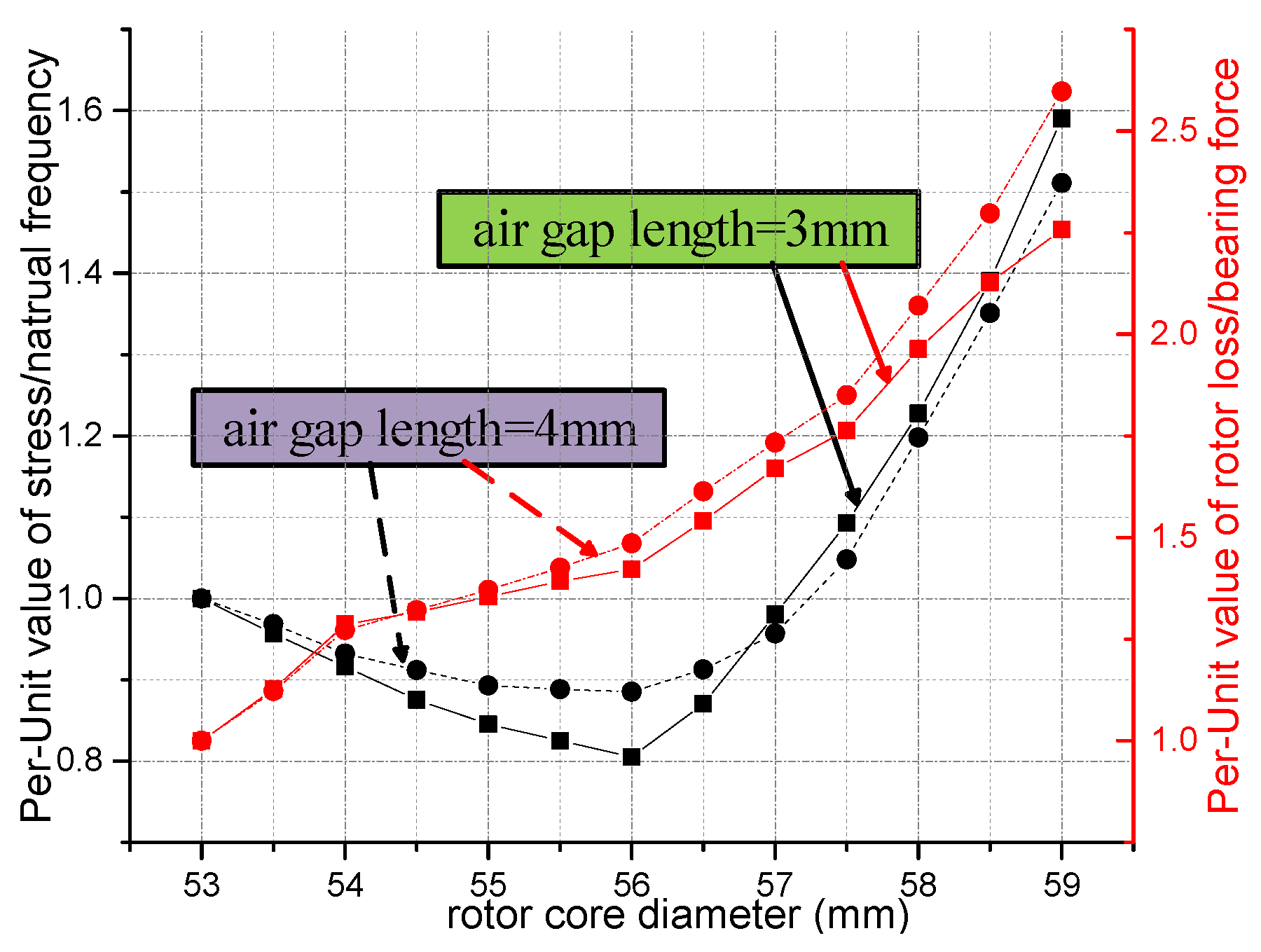
To obtain integrated optimal design results, synthesis of different performance of rotor among several design aspects is necessary, as
Figure 9 shows this selection of design point of rotor diameter. As can be seen in it, the ratio of stress to natural frequency, just as
, however, the Per-Unit value of it,
, is used to eliminate the effect of dimension here, as the left black vertical axis shows, corresponding to two black curves in
Figure 9, where
is the initial value when the rotor diameter is 53 mm, thus, the Per-unit value of the ratio of rotor loss to bearing force is represented by the right red axis, also corresponding to red curves in
Figure 9, namely
. Thus, these two Per-Unit values are all designed to minimize, so out-diameter of rotor is selected as 56 mm with representative air gap length 3 mm and 4 mm under comprehensive consideration. Besides, the variation tendency of them, and each respective design objective and aspect, all influence the selection point. So, dynamic variables of rotor are further determined. After above optimal selection, the air gap is 3 mm, where rotor loss is 1970 W at 60,000 rpm, radial bearing force can reach 270 N with normal amplifier. Besides, from
Figure 9, the design sensitivity of
to the diameter of rotor has little variation approximately, while, the sensitivity of
begins to increase obviously when the out-diameter of rotor starts to increase from 57 mm, which is the inflection point for sensitivity. In the light of robust design, the out-diameter of rotor may affect the performance more obviously from 56 mm.
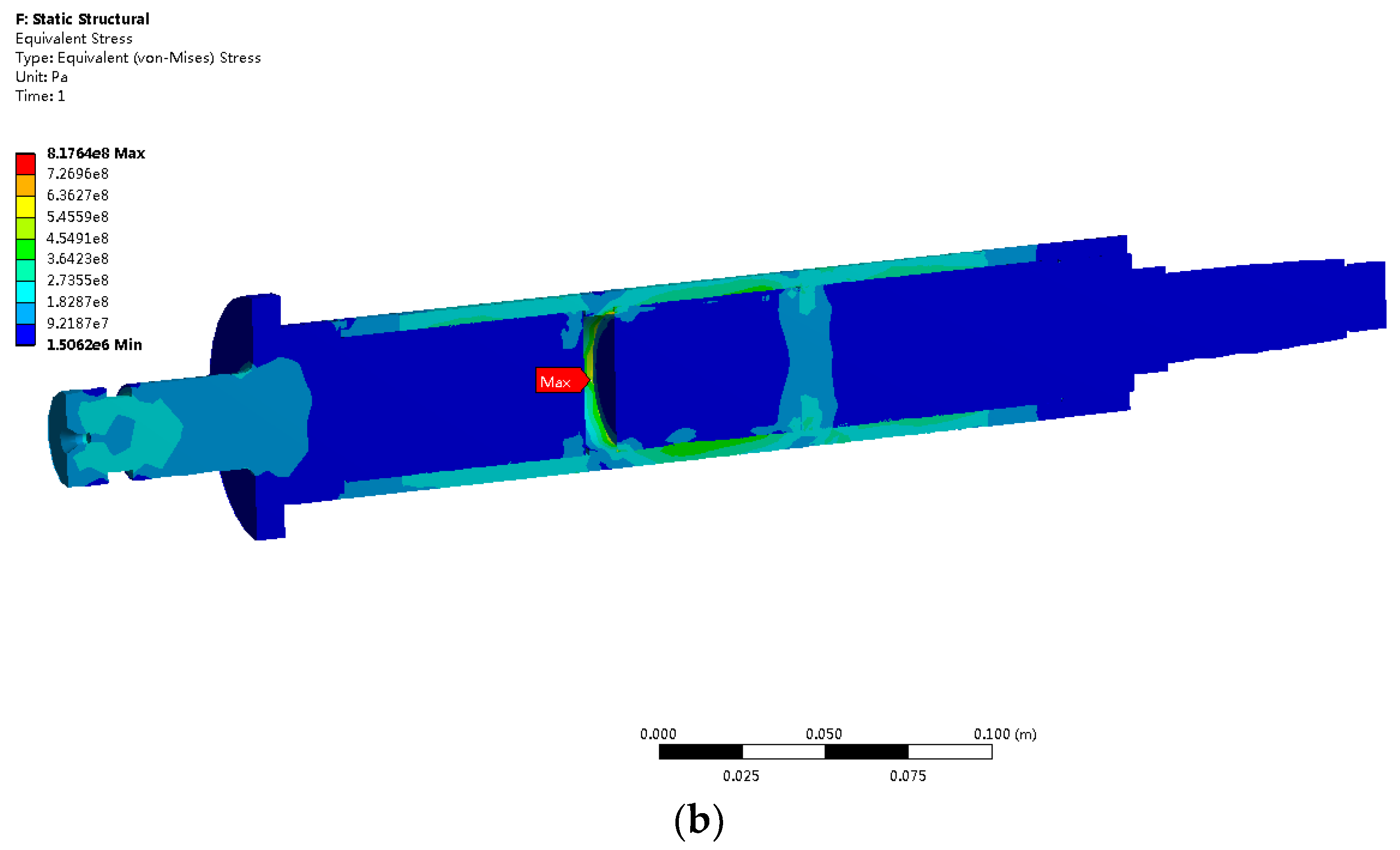
With final design, the contact pressure in an interference fit is analyzed by means of the numerical simulations using FEM (using Ansys 14.0 to establish load and boundary condition). Thus, the equivalent effective stress contours of the sleeve are shown in
Figure 10b. The maximum equivalent stress of sleeve is 663 MPa, with safety factor being 2. Based on the same FEM process, the maximum equivalent stress of the permanent magnet is 21.8 MPa with safety factor 3.67.
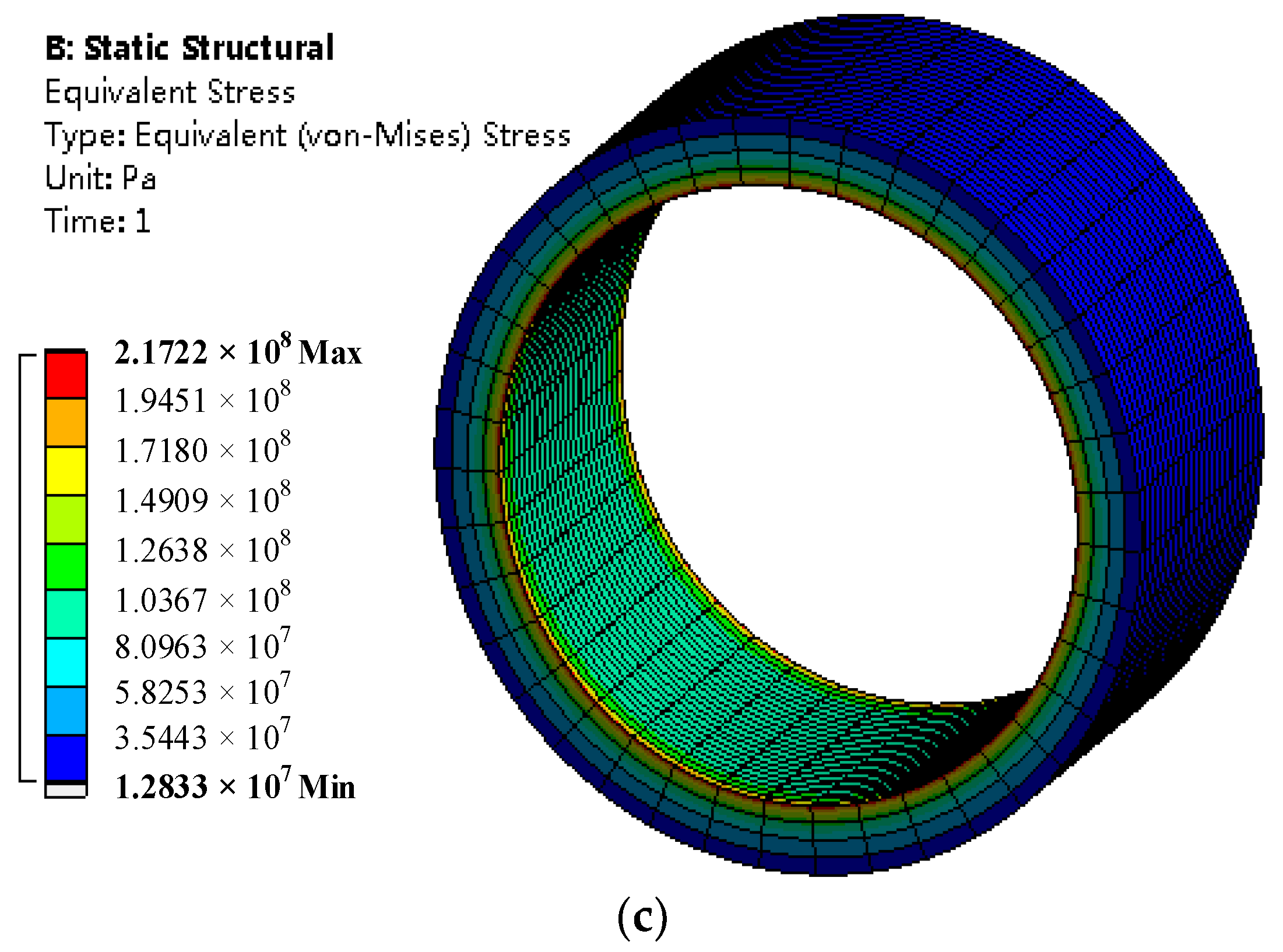
Figure 10c shows the equivalent effective stress distribution of the RMB rotor core. The maximum equivalent stress of it is 217 MPa. The yield stress in rotor core of the RMB is 380 MPa. The safety factor is 1.75.
3.4. Thermal Design Considering Electromagnetic Aspect
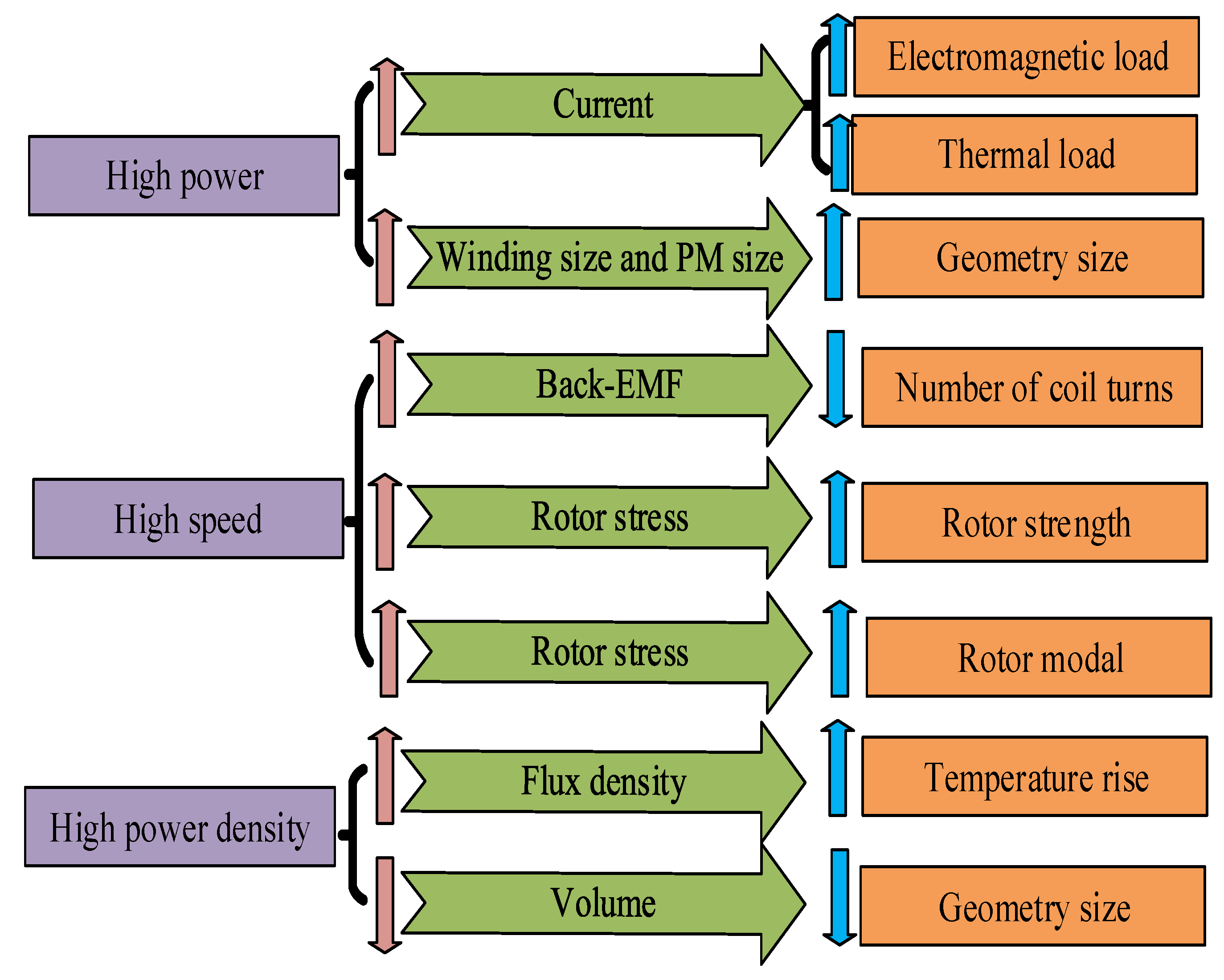
The crucial requirements and limitations for high power density and high speed motor could come down to the temperature sustainability and thermal reliability. High current density in coils and volume limitations of BLDCM could lead to high temperature rise, thus, also lead to thermal design selection as for high speed motor. Besides, the cooling ability decides the thermal property of BLDCM, which is influenced by air gap lengths of motor and MBs, with the air cooling and water jackets improving it, which are all set as design feedback interface for structural design. Temperature rise of each part in motor system should be below the allowable temperature rise with permitted allowance reserved.
FEM process of three dimensional steady thermal field and fluid field of this BLDCM deserves fundamentals of heat transfer, namely, with regard to analyzation of steady thermal field, steady heat conduction equation does not contain the time term, meanwhile, including heat source and medium, which can be expressed as the shown below:
The boundary condition in adiabatic surface is , while in radiating surface is .
After heat transfer coefficients being determined, with every heat source and heat generation rate has been obtained (as
Table 8 shows) and assigned to corresponding area, temperature rise can be got by (18) via FEM. Here, thermal analysis takes the form of validation by FEM for the final determination of dynamic variables as the final interface.
With similar ideas to
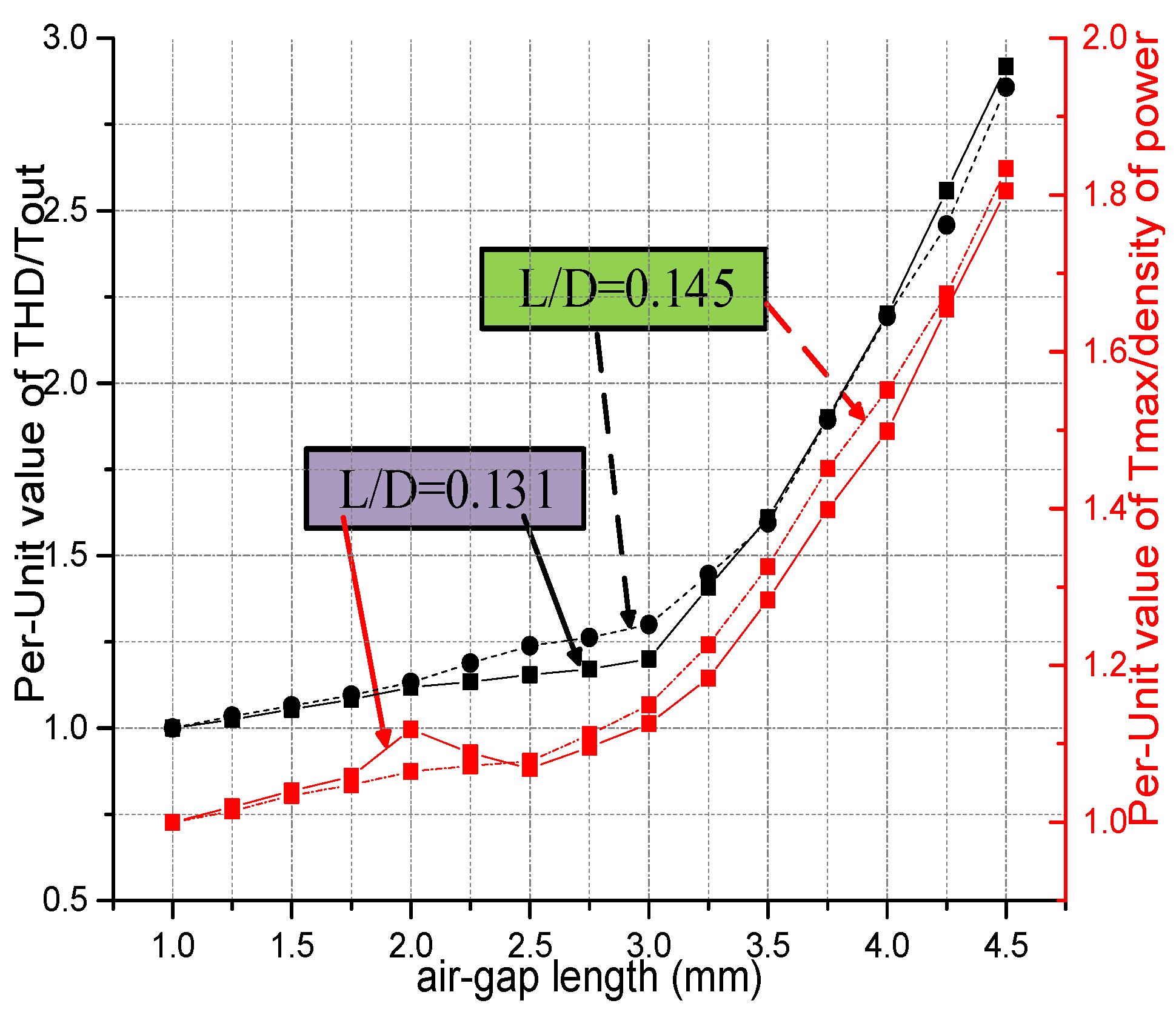
Figure 9, synthesis of electromagnetic, thermal, and power performance is implemented as
Figure 11 shows for selection of design point of air gap length. In the same way, Per-Unit values of the ratio of total harmonic distortion (THD) to output torque and the ratio of maximum temperature to density of power have the same corresponding relationships with vertical axes as the ones of
Figure 9. Minimum of Per-unit values are optimal for design, considering with rotor dynamics requirements, 3 mm air gap length is selected, approximate to inflection point, with different ratios of length of rotor to diameter (as L/D in
Figure 11, 0.131 is the optimal value) are considered. While THD = 9.6%, Tmax = 139 °C. Besides, from
Figure 11, sensitivity about air-gap length begins to increase immediately when air-gap value is 3 mm. It affects performance remarkably when its value is more than 3 mm. It also can be seen from the sensitivity that the air-gap length is a key parameter that it should be set as the dynamic variable to coordinate every design model and determine the overall performance of the high speed BLDCM.
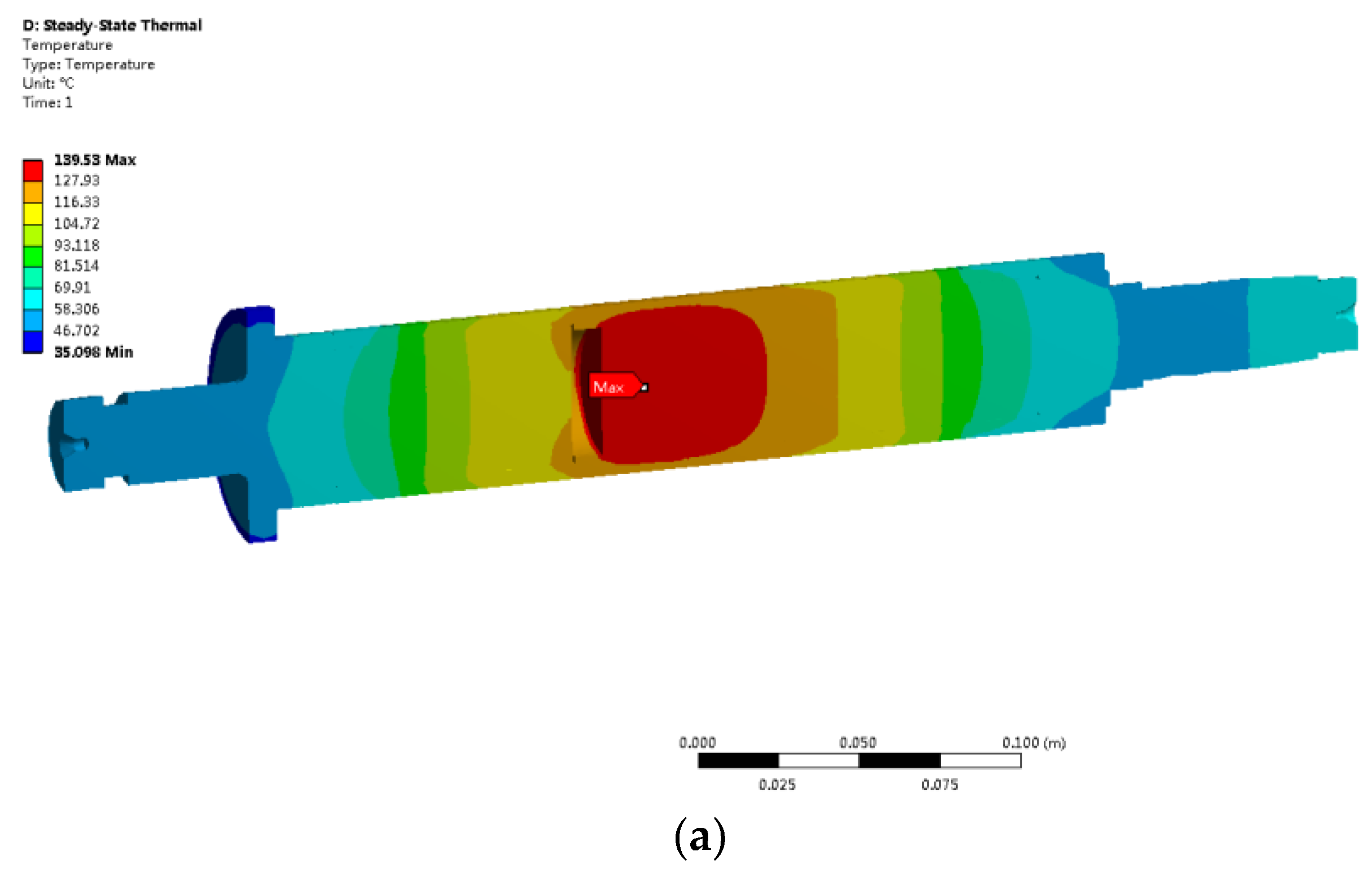
Accounting for boundary conditions, with assignment of those heat source values in
Table 8, the thermal solution can be obtained by FEM, however, in which heat transfer coefficients (HTC) are key values for it. Definition of HTC in air gap and jackets are described in [
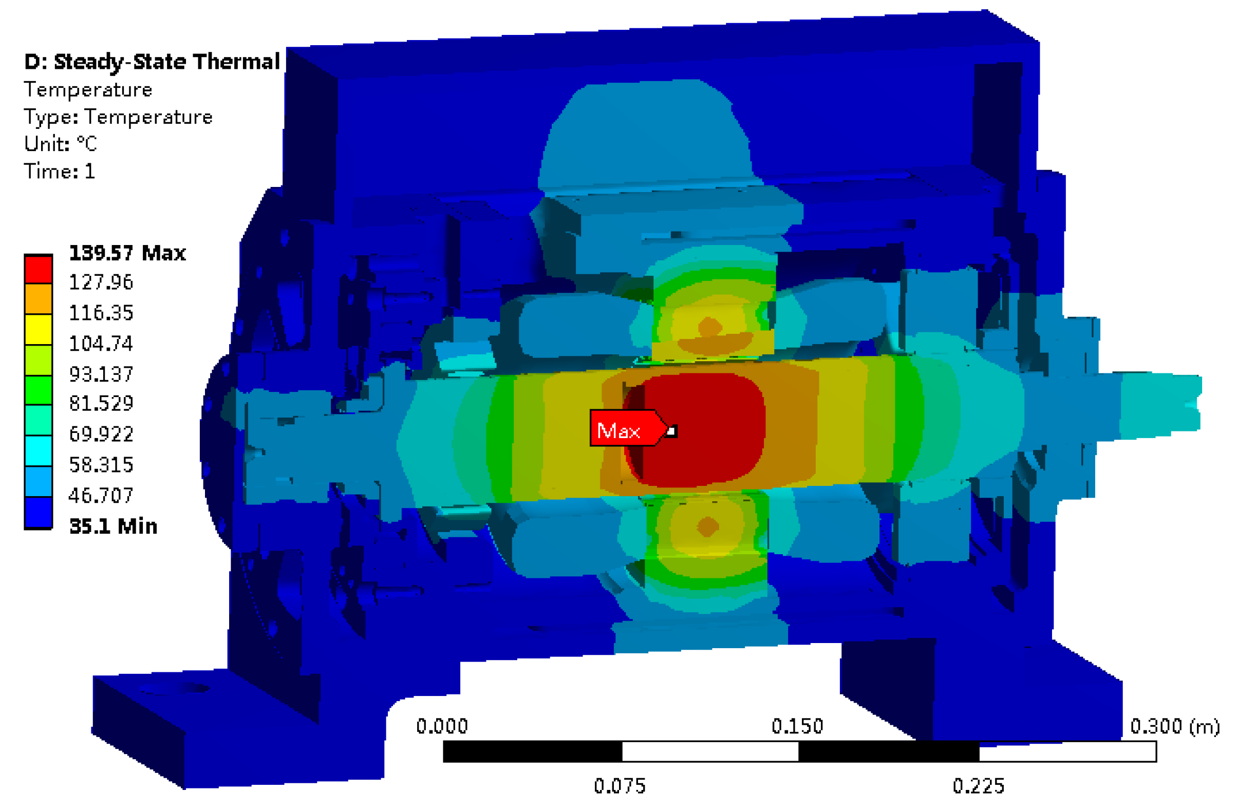
29] by computation fluid dynamics (CFD) method, with others are defined by material properties, empirical formulas, and values. The highest temperature is 139 °C located in the positive center in cylindrical PM as
Figure 12 (in lower right corner) shows. The temperature of sleeve and PM can be substituted into (22) to validate their thermal stress to make thermal-mechanical coupling. Besides, the highest temperature of PM is beyond its demagnetization point. While at of the stator is beyond 90 °C (in upper right corner in
Figure 12), which can promise the insulation of the winding below the safety value. Thus, the final values of the dynamic optimal variables are determined after the thermal analysis and selection process, based on
Figure 11 as
Table 9 shows.


