Article

Influence of Single/Dual Ventilation Path on Fluid Field and Temperature Field of HVLSSR-PMSM with Air-Cooled Hybrid Ventilation Systems

1
School of Electrical Engineering, Beijing Jiaotong University, Beijing 100044, China
2
School of Electrical and Automation Engineering, East China Jiaotong University, Nanchang 330013, China
*
Author to whom correspondence should be addressed.
Energies 2018, 11(6), 1343; https://doi.org/10.3390/en11061343
Submission received: 27 April 2018 / Revised: 21 May 2018 / Accepted: 22 May 2018 / Published: 25 May 2018

Abstract

:
Due to the solid rotor structure, High-Voltage Line-Start Solid Rotor Permanent Magnet Synchronous Motor (HVLSSR-PMSM) operates with high rotor temperature rise. If the ventilation path cannot take the rotor heat away in time, the rotor will overheat or even may led to the thermal demagnetization for permanent magnet. Therefore, it is of great significance to study the thermal issues of HVLSSR-PMSM. In the paper, the fluid field and temperature field of a 315 kW, 6 kV HVLSSR-PMSM with air-cooled hybrid ventilation systems are investigated. Firstly, the electromagnetic analysis of the machine is done by using the finite-element method, the loss distributions then are obtained, which will be assigned as the heat source for thermal analysis. Then, the three -dimensional (3-D) fluid thermal coupled mathematical model for thermal analysis of HVLSSR-PMSM is established. The temperature field and the fluid flowing state of HVLSSR-PMSM with single ventilation path air-cooled system are investigated by using the established 3D fluid thermal coupled mathematical model. A dual ventilation path air-cooled system for HVLSSR-PMSM is proposed to reduce the operating temperature rise. Then, the temperature field and fluid field of HVLSSR-PMSM with dual ventilation system are analyzed by comparing with single ventilation system. Moreover, the temperature experiments are carried out on the machine with dual ventilation system to validate the accuracy of the established mathematical models. The results show that the proposed dual ventilation path air-cooled system can effectively improve the thermal distribution of HVLSSR-PMSM, whilst it can also reduce the working temperature rise of the machine.

1. Introduction

The high -voltage line -start solid rotor permanent magnet synchronous motor (HVLSSR-PMSM) has attracted much attention as a candidate for heavy duty applications such as pumps for cooling system in power plants, large air compressor for mines, and fans, due to their inherent advantages of high efficiency, high power factor, high starting torque, and low starting current [1,2]. In the actual operation of solid rotor permanent magnet (PM) synchronous motor, the rotor eddy current loss is considerably large. If the design of the air-cooled system structure is not reasonable, the stator and the rotor may operate with a high temperature. Therefore, it is of great significance to study the ventilation path air-cooled system in solid rotor PM machines to reduce the temperature rise and improve the reliability and operation life.
Scholars have done lots of research on starting and operating performance, ventilation system, and thermal problems of the permanent magnet synchronous motors. The improvements of PMSM performance have been studied in [3,4,5,6,7,8,9,10,11], which illustrated the synchronous process and indicated the effective parameters to starting capability, such as inertia, load torque, supply voltage, rotor eddy current loss, and rotor bar size. In [12], a composite rotor structure is proposed to improve demagnetization capability of a high-speed PMSM, the performance is studied by using the fluid-thermal coupling method. The determination of pole spacer materials for a high-speed surface-mounted PMSM is made by Yuan W. in [13], which can be used to improve the rotor temperature rise and thermal stress. Taking advantages of the small thermal resistance, the heat pipes are installed in the connection joint between stator tooth root and shaft of an outer-rotor PMSM, which is of little influence on the main magnetic path, whereas the heat generated in the windings could be transferred to the heat pipe [14]. The thermal network methods have been studied in [15,16], which are used to estimate the temperature of the permanent magnet motor quickly. To analyse the cause of local irreversible demagnetization, the authors performed a parameter analysis of the magnetic field based on the barrier width and magnet position considerably related to the magnetic path using the finite-element method [17]. In [18,19,20], the fluid heat transfer method is used to calculate the internal fluid flowing state and the temperature distributions of each component.
Although lots of achievements have been delivered by former researches, there are few cases that focus on the large solid rotor PM machines, especially those with novel air cooling system investigated via the fluid heat transfer coupled analysis. Furthermore, there is little research on the ventilation system and the thermal problem of HVLSSR-PMSM. Therefore, in this paper, the thermal performance of a 315 kW, 6 kV, 6-pole HVLSSR-PMSM is investigated. According to the physical structure of the machine and the air-cooled system, the loss distributions of the machine is analyzed by using transient electromagnetic field model. Then, the loss is assigned as the heat source for the thermal analyses. The fluid thermal coupled mathematical model is established, then the fluid flowing state and thermal field of HVLSSR-PMSM with single ventilation path is studied. In order to reduce the temperature rise of the HVLSSR-PMSM, the dual air-cooled ventilation systems are presented and the fluid field and thermal field are also investigated by comparing with that with single ventilation path. Moreover, the temperature experiments are carried out on the machine with dual ventilation system to validate the accuracy of the established mathematical models. The obtained results could provide a reliable basis for the design of new cooling system for large solid rotor PM machines, as well as the methodology.

2. Basic Structure Description of High-Voltage Line-Start Solid Rotor Permanent Magnet Synchronous Motor (HVLSSR-PMSM)

The basic design parameters of HVLSSR-PMSM are shown in Table 1.
The internal structure of HVLSSR-PMSM is as shown in Figure 1. The stator windings chose a double-layer short-pitch configuration. The bars are embedded in the solid rotor, and the sleeve is inserted between the permanent magnet and the shaft. Materials properties of each part of the motor are as shown in Table 2.
Based on the literature [19], the 2D transient electromagnetic field mathematical model is established, as shown in Figure 2.
For the convenience of analysis, the following assumptions have been made to simplify the solution procedure [18]:
(1)
The influences of displacement current and the skin effect of the stator windings are ignored. As the dimension of single rectangle coil is 1.4 × 6.7 mm, which is smaller than the skin depth 9.3 mm (fundamental operating frequency 50 Hz) and 3.3 mm (harmonic frequency 400 Hz). Thus, during the electromagnetic filed calculation, the proximity effects are ignored.
(2)
Materials are anisotropy.
(3)
The effects of temperature on the conductivity and permeability of the material are ignored.
By using the time-step finite element method (FEM), the established mathematical model of the motor is solved. Once the calculations are done, the stator copper loss, the stator core loss, the eddy current loss of solid rotor, bars, and permanent magnet are obtained as listed in Table 3.

3. Calculation and Analysis of Fluid and Heat Transfer of HVLSSR-PMSM

Taking the obtained loss distributions of HVLSSR-PMSM as the heat source for thermal analysis, the fluid thermal coupled calculation model is set up according to the heat transfer theories. Similar as the electromagnetic field calculations, the fluid thermal coupled calculation model can be also solved by using FEM.

3.1. Fundamental Assumptions

On the basis of satisfying the actual project, the following hypotheses are proposed:
(1)
The influence of the buoyancy of cooling medium on fluid flowing is neglected.
(2)
The air-cooled medium flow rate is far less than the sound velocity, so the fluid is treated as incompressible fluid.

3.2. Mathematical Model

The flow of air in the motor needs to satisfy the energy conservation equation, mass conservation equation, and momentum conservation equation. The mathematical equations of the fluid-thermal coupling of the motor are shown as follows [1]:
{ ρ t + d i v ( ρ u ) = 0 ( ρ u ) t + d i v ( ρ u u ) = d i v ( ϕ g r a d u ) P x + S u ( ρ v ) t + d i v ( ρ u v ) = d i v ( ϕ g r a d v ) P y + S v ( ρ w ) t + d i v ( ρ u w ) = d i v ( ϕ g r a d w ) P z + S w ( ρ T ) t + d i v ( ρ u T ) = d i v ( λ c g r a d T ) + S T ,
where, ρ is mass density (kg/m3); u is the velocity vector; u , v , w are the velocity vector. P is pressure (Pa); S u , S v , S w are the conservation of momentum of the generalized source term in x, y, z, direction, respectively. S T is the heat source, ϕ is the dynamic viscosity coefficient [kg/(m∙s)], λ is the thermal conductivity [W/(m∙K)], c is the specific heat [J/(kg∙°C)], and T is the temperature (°C).
To calculate the flow of air in a turbulent state, the fluid flowing is calculated by the standard k–ε model [1]:
{ t ( ρ k ) + d i v ( ρ k u ) = d i v [ ( μ + μ t σ k ) g r a d k ] + G k ρ ε t ( ρ ε ) + d i v ( ρ u ε ) = d i v [ ( μ + μ t σ ε ) ] + G 1 ε ε k G k G 2 ε ρ ε 2 k ,
where, k is the turbulent kinetic energy, ε is the diffusion factor, Gk is the turbulence dissipation rate, G1ε, G2ε are constants, and σk and σε are the Planck constants.
The fluid flowing in HVLSSR-PMSM is exactly complex because of the asymmetry of the ventilation system and the rotor rotation effect. Therefore, it is necessary to establish a global fluid thermal coupled calculation model to accurately calculate the flow rate of the motor and the temperature distribution of each component. Considering the existing computer speed, the motor and the cooler are modeled into two parts, as shown in Figure 3. Figure 3a is the cooler calculation model, and Figure 3b is the motor calculation model. The temperature of the outer loop air inlet and the outer loop air outlet can be measured. However, the temperature of the inner loop air inlet is difficult to obtain by measurements. Therefore, the temperature of the inner loop air inlet is determined by the temperature iteration calculation between the cooler calculation model and the motor calculation model.
In order to avoid the instability of the computation, structured grid is used in the model. The hexahedron mesh is adopted for more than 90% in the model. The cells number is 4,466,880. The calculation model is established by using software Gambit. The flow and temperature in the motor are obtained from the CFD software Fluent (Fluent 14.5, ANSYS, Pittsburgh, PA, USA). The solving domain of HVLSSR-PMSM is meshed, as shown in Figure 4.

4. Analysis of Fluid Field and Temperature Field of HVLSSR-PMSM with Single Ventilation Path

4.1. The Effect of Single Ventilation Path on the Fluid Field of High-Voltage Line-Start Solid Rotor Permanent Magnet Synchronous Motor (HVLSSR-PMSM)

The air-cooled hybrid ventilation systems of HVLSSR-PMSM with single ventilation path is shown in Figure 5. The single ventilation path is composed of two cooling loops: the out cooling loop and the inner cooling loop, as shown in Figure 5. In the out loop, the air enters into the cooler from the out loop air inlet. Then the air that pushed by the centrifugal fan goes into the aluminum tubes, by which the hot air in the inner loop is cooled. Finally, the warm air flows into the outside from out loop air outlet. Whereas, for the inner cooling loop, the cooling air in the inner loop flows into the motor from the inlet forced by the axial fan, and all the air passes the air gap, the stator radial ducts, and the axial ducts located at stator back yoke. The heat generated within the motor components can be taken away by the cooling air, and then the temperature of the cooling air will arise; finally, the heat of high temperature cooling air will be transferred to the air in the out cooling loop.
In inner loop, the warm air in the outlet flows through the cooler and then flows back into the motor inlet, and the cycle repeats.
According to the ventilation system structure of HVLSSR-PMSM with single ventilation path, the inner loop wind resistance equivalent model of the motor including the axial fan and the cooler is established, and then the air-flow equivalent network of the motor is solved. The boundary conditions of the inlet and outlet of the motor are determined.
The boundary conditions of the calculation model of HVLSSR-PMSM with single ventilation path are as follows:
(1)
The inlet boundary conditions for a given mass flow inlet of the motor, whose mass flow is 0.075 kg/s.
(2)
The boundary conditions of the given pressure of the outlet of the motor, of which the ambient pressure is 1 atm.
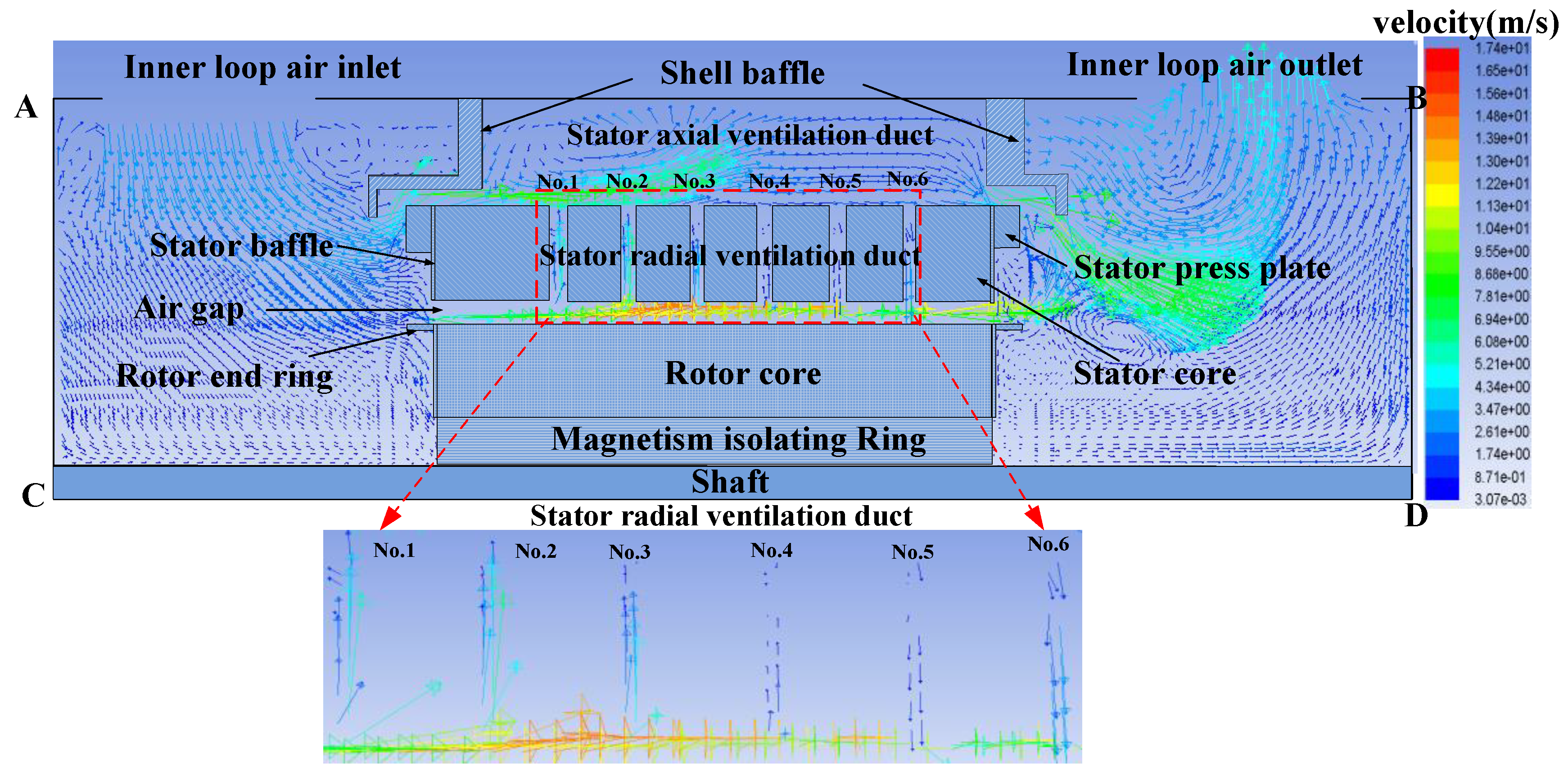
Based on the theories of the computational fluid dynamics, the finite volume method is adopted to calculate the whole region 3D fluid-thermal coupled fields, both the fluid and the temperature distributions inside the HVLSSR-PMSM are obtained by using established 3D fluid thermal coupled model. According to the experimental environment, the ambient temperature is set as 16 °C. Considering the structure of prototype, the cross-section A-B-C-D section in Figure 4 is emphasized, and the fluid distribution in HVLSSR-PMSM with single ventilation path is shown in Figure 6.
The fluid velocity in Figure 6 is described as the composed vector of the axial velocity, circumferential velocity, and the radial velocity. As seen from Figure 5, all the cooling air enters the air gap, so that the wind velocity in the air gap is increased. The internal flow maximum velocity of the motor is 17.2 m/s, which appears in the air gap corresponding to No. 4 stator radial ventilation duct.
In order to facilitate analysis, we assumed that the direction of fluid flowing from the stator teeth to the stator back yoke belongs to the out-wind zone and those with fluid moving from the stator back yoke to the stator teeth as the in-wind zone.
By viewing cross-section A-B-C-D in Figure 6, No. 1, No. 2, No. 3, and No. 4 stator radial ventilation ducts pertain to the out-wind zone, and No. 5 and No. 6 stator radial ventilation ducts are within the in-wind zone.
The exchange of the flow and the heat between air gap and stator yoke back axial ventilation duct is realized by stator radial ventilation ducts. Meanwhile, the stator radial ventilation ducts are also the main paths of the stator windings heat dissipation. The velocity and the temperature of the fluid inside the stator radial ventilation ducts have a great influence on the temperature distribution of the stator windings. To estimate their thermal effects, the radial flowing velocity of fluid of the stator radial ventilation ducts are investigated. The average velocity of air in all circumference stator radial ventilation ducts at the same radial positions is analyzed, and the changing trend of the radial flowing velocity of fluid of the stator radial ventilation ducts are shown in Figure 7.
Figure 7a shows the air flowing into the stator radial ventilation ducts from the air gap. The fluid velocity is larger and it changes obvious along radial direction of the machine because of the smaller ventilation area of the stator teeth. The maximum flow velocity locates at the top of the stator tooth. As the air goes further to the stator tooth root, the fluid velocity is almost linearly decreasing due to the increasing area of the ventilation ducts. While the cooling air goes through the stator yoke, the flowing velocity reduces rapidly.
The maximum velocity of flow in No. 1 stator radial ventilation duct is 1.81 m/s. The velocity of flow decline to 1.3 m/s at the stator tooth root, and the velocity of flow at the yoke back is the minimum, which is 0.13 m/s. The trends of fluid in No. 2, No. 3, and No. 4 stator radial ventilation ducts are basically the same as that in No. 1 stator radial ventilation duct, but obviously different in the velocity values. The maximum velocity of flow in No. 2, No. 3, and No. 4 stator radial ventilation duct are 1.58 m/s, 1.31 m/s, and 0.72 m/s, respectively.
From Figure 7b, in the out-wind zone, the velocity of flow at the yoke back inlet is the lowest in No. 6 stator radial ventilation duct, which is 0.08 m/s, and the velocity of flow rise to 2.39 m/s at the tooth root. The velocity of flow in stator tooth region along radial direction increases dramatically, and the maximum velocity reaches 4.31 m/s. The velocity of flow distribution of air in No. 5 stator radial ventilation duct is similar to that air in No. 6 stator radial ventilation duct, in which the lowest velocity of flow in the yoke back is 0.015 m/s, and the velocity of flow in tooth root region is 0.39 m/s. The maximum velocity of flow in No. 5 stator radial ventilation duct is 0.76, which is located near the wedge.

4.2. The Effect of Single Ventilation Path on the Temperature Field of HVLSSR-PMSM

The variation of the velocity of flow in the stator radial ventilation duct will directly affect the temperature distribution of each component in the motor. By solving the 3D fluid thermal coupled calculation model, the 3D temperature distribution of the components in the motor with single ventilation path are obtained, as shown in Figure 8.
In Figure 8, the maximum temperature difference of HVLSSR-PMSM with single ventilation path is 100 °C. The lowest temperature in the motor is 180 °C, which locates at the end windings that near the fan end. The temperature of each component gradually increases from the fan end to the shaft end in the axial direction. The highest temperature in the stator core is 270 °C, and the highest temperature in the stator winding is 280 °C, but it is 230 °C for rotor core and permanent magnet.
In this paper, the permanent magnet used for the machine is NdFeB (N35EH160), which has a maximum temperature of 200 °C. The magnetic properties and demagnetization curves are illustrated in Figure 9. The highest temperature of the permanent magnet in HVLSSR-PMSM with single ventilation path is 230 °C, which has exceeded the maximum temperature for utilization. The highest temperature could affect machine performance and even led to the thermal demagnetization for permanent magnet.
By testing the prototype of HVLSSR-PMSM with single ventilation path, the temperature rises of stator and rotor in the motor are higher than the insulation material. Due to the large internal wind resistance, the wind pressure provided by the axial flow fan cannot supply sufficient cooling air flowing velocity. Meanwhile, the air amount inside the motor is less and the cooling channel design is unreasonable, so that the air cooling system cannot effectively reduce the temperature rise in motor.
Therefore, the air-cooled ventilation systems with single ventilation path is optimized to a dual ventilation path.

5. Analysis of Fluid Field and Temperature Field of HVLSSR-PMSM with Dual Ventilation Path

5.1. The Effect of Dual Ventilation Path on the Fluid Field of HVLSSR-PMSM

The above analysis shows that the stator and rotor of HVLSSR-PMSM with single ventilation path have higher temperature. In order to reduce the temperature rise and improve the internal fluid flow unreasonable situation of the motor, the air-cooled system is changed to dual ventilation path. In the new optimized ventilation system, the axial throughout ducts are added to stator back yoke, as shown in Figure 10. Based on the thermal network calculation model above, modifications to deal with the new yoke back ducts are performed. Due to the change of wind resistances inside the motor, the air amount inside the motor is changed. Therefore, the wind resistance equivalent model of HVLSSR-PMSM with dual ventilation path is obtained and solved, and the flow rate of inner loop air inlet is determined.
The boundary conditions of the calculation model of HVLSSR-PMSM with dual ventilation path are as follows:
(1)
The inlet boundary conditions for a given mass flow inlet of the motor, whose mass flow is 0.4 kg/s.
(2)
The boundary conditions of the given pressure of the outlet of the motor, of which the ambient pressure is 1 atm.
The air-cooled hybrid ventilation systems of HVLSSR-PMSM with dual ventilation path is shown in Figure 10.
It shows that the cold air from the inner loop air inlet into the motor is divided into two parts. One part of air enters into the air gap, and the other cooling air enters the stator axial ventilation duct. The internal flow maximum velocity of the motor is 17.4 m/s, which appears in the air gap corresponding to No. 2 stator radial ventilation duct. The fluid distribution within the cross-section A-B-C-D of the fluid distribution of HVLSSR-PMSM with dual ventilation path is shown in Figure 11.
As shown in Figure 11, No. 1, No. 2, and No. 3 stator radial ventilation ducts pertain to the out-wind zone, and No. 4, No. 5, and No. 6 stator radial ventilation duct pertain to in-wind zone.
The flow velocities of fluid in stator radial ventilation ducts vary greatly after the change of ventilation path. The average velocity of air in all circumference stator radial ventilation ducts at the same radial positions is investigated, and the changing trend of the radial flowing velocity of fluid of the stator radial ventilation ducts of HVLSSR-PMSM with dual ventilation path are shown in Figure 12.
In Figure 12a, No. 1, No. 2, and No. 3 stator radial ventilation ducts belong to the out-wind zone. The maximum fluid flowing velocity locates near the top of the stator tooth. The maximum fluid flowing velocity in No. 1 stator radial ventilation duct is 1.69 m/s. The velocity of flow decline to 1.2 m/s at the stator tooth root, and the velocity of flow at the yoke back is the minimum, which is 0.4 m/s. The maximum fluid flowing in No. 2 stator radial ventilation duct is 1.3 m/s, and it is about 0.6 m/s for fluid in No. 3 stator radial ventilation duct.
By comparing the fluid velocity in No. 1, No. 2, and the No. 3 stator radial ventilation duct, it can be seen that the fluid flowing velocity in No. 1 stator radial ventilation duct is the largest one, which indicates that the heat dissipation effect is relatively well cooled.
In Figure 12b, No. 4, No. 5, and No. 6 stator radial ventilation ducts belong to the out-wind zone. In the stator radial ventilation duct tooth region, as the ventilation area becomes smaller, the flow velocity increases gradually. The maximum fluid flowing velocity appears at in the top of the stator tooth. It has the smallest velocity in No. 4 stator radial ventilation duct, and the maximum fluid flowing velocity is only 0.5 m/s.
The lowest fluid flowing velocity in No. 5 stator radial ventilation duct is 0.3 m/s, located in the yoke back inlet, and the flow velocity rises to 1 m/s at the tooth root. The flow velocity in stator tooth region along radial direction increased and the maximum fluid flowing velocity is up to 1.45 m/s. The fluid flowing velocity distribution of air in No. 6 stator radial ventilation duct is similar to the air in No. 5 stator radial ventilation duct. The lowest fluid flowing velocity in No. 6 stator radial ventilation duct is 0.5 m/s, the fluid flowing velocity in tooth root region is 2 m/s, and the maximum fluid flowing velocity near the stator slot wedge is 3.63 m/s.
The fluid flowing velocity in No. 6 stator radial ventilation duct is the largest of those in all stator radial ventilation duct. The fluid flowing velocity in No. 1 stator radial ventilation duct which is close to the fan end is lower than that fluid flowing velocity in No. 6 stator radial ventilation duct, so that the lowest temperature locates at this region. On the contrary, the fluid flowing velocity in No. 4 stator radial ventilation duct is less than that of other stator radial ventilation ducts.
According to the calculation results of fluid field, the air volume of air gap inlet, air gap outlet, and the stator axial ventilation duct inlet and outlet are obtained. The air amount is as shown in Table 4.
It can be seen in the Table 4 that the air account of flow into the stator axial ventilation duct is about eight times of that to the air amount of entering the air gap. It is because that the stator axial ventilation duct inlet area, which is larger than the air gap inlet area. In addition, due to the rotating of rotor, some circumferential fluid pressure is generated in air gap, which prevents the entering of cooling air in some case.
In addition, the air amount of air gap outlet is 12.27%, is 1.1% larger than that of air gap inlet. Some of the air in the stator axial ventilation duct enters the air gap. However, the sum of the flow rate at the inlet of the air gap and stator axial ventilation duct equals to the sum of the flow rate at the outlet of the air gap and stator axial ventilation duct.

5.2. The Effect of Dual Ventilation Path on the Temperature Field of HVLSSR-PMSM

The air-cooled effects of HVLSSR-PMSM are related to the stator axial ventilation ducts, stator radial ventilation ducts, the cooling air volume, and its velocity in air gap. By using the same method, the 3D fluid-thermal coupled calculation model is solved. The three-dimensional temperature distribution of the components in the motor with dual air air-cooled system are obtained, as shown in Figure 13.
As shown in Figure 13, the maximum axial temperature difference of HVLSSR-PMSM with dual ventilation path is 74 °C. The lowest temperature in the motor is 105 °C, which is located at the windings end near the fan end. The temperatures of each component gradually increased from the fan end to the shaft end in the axial direction. The highest temperature in the stator core, stator windings, rotor core, and permanent magnet are 155 °C, 150 °C, 179 °C, and 178 °C, respectively.
Six negative temperature coefficient (NTC) thermistors are embedded in the prototype of HVLSSR-PMSM, and the practical test rig and facilities are shown in Figure 14. At the temperature measurement locations, the experimental temperature values are compared with the simulation dates, as shown in Table 5.
To measure the end windings temperature, one temperature sensor is embedded at the fan end windings and the other temperature sensor is embedded at axle stretch end windings. The experimental and simulation results of temperature in end windings are shown in Table 6.
The reason for the different trend is that the position of the temperature measurement point may be shifted at the time of installation, which leads to a slight difference between the calculated value the measured value of the permanent magnet temperature.
However, it can be seen from Table 5 and Table 6 that the calculated temperature of the permanent magnet and end windings are close to the experimental result, which shows that the established calculation model is in accordance with the actual situation and satisfies the requirements of calculation accuracy.
A comparison of Figure 8 and Figure 13 indicates that the highest temperature of stator core, stator windings, rotor core, and permanent magnet in HVLSSR-PMSM with dual ventilation path are reduced by 115 °C, 130 °C, 51 °C, and 52 °C, respectively. It is shown that the temperature distribution of the stator and rotor are obviously improved by the dual ventilation path cooling system.

6. Conclusions

In this paper, a 3D fluid thermal coupled model for HVLSSR-PMSM has been established. The fluid field and temperature field in the motor with different ventilation systems are calculated. The following conclusions could be obtained.
(1)
Influenced by the air gap inlet area and the wind pressure of the fan, the air volume of HVLSSR-PMSM with single ventilation path is relatively small so that the highest temperature of stator core, stator windings, rotor core, and permanent magnet are 270 °C, 280 °C, 230 °C, and 230 °C, respectively. The air-cooled hybrid ventilation systems of HVLSSR-PMSM with single ventilation path is not reasonable. If the motor works in high temperature for a long time, it will cause high temperature rise that could reduce the utilization life and the reliability, or even cause the machine damaged.
(2)
While the internal air-cooled ventilation systems of single ventilation path are changed to the dual ventilation path, the temperature of the stator core, stator winding, rotor core, and permanent magnet decrease obviously, and the highest temperature of stator core, stator windings, rotor core, and permanent magnet are reduced to 155 °C, 150 °C, 179 °C, and 178 °C, respectively.

Author Contributions

Z.C. wrote the paper; W.L. supervised all processes; X.Z. analyzed the data; Y.F. checked paper format; J.Z. implemented simulation.

Acknowledgments

This work was supported by the national special project for international scientific and technological cooperation under Grant 2015DFR70060, the fundamental research funds for the central universities under Grant 2016RC028.

Conflicts of Interest

The authors declare no conflict of interest.

References

  1. Cao, Z.; Li, W.; Li, J.; Zhang, X.; Li, D.; Zhang, M. Research on the Temperature Field of High-Voltage High Power Line Start Permanent Magnet Synchronous Machines with Different Rotor Cage Structure. Energies 2017, 10, 1829. [Google Scholar] [CrossRef]
  2. Ding, T.; Takorabet, N.; Sargos, F.M.; Wang, X. Design and Analysis of Different Line-Start PM Synchronous Motors for Oil-Pump Applications. IEEE Trans. Magn. 2009, 45, 1816–1819. [Google Scholar] [CrossRef]
  3. Jędryczka, C.; Knypiński, Ł.; Demenko, A.; Sykulski, J.K. Methodology for Cage Shape Optimization of a Permanent Magnet Synchronous Motor Under Line Start Conditions. IEEE Trans. Magn. 2018, 54, 8102304. [Google Scholar] [CrossRef]
  4. Esmaeil, S.; Sadegh, V.-Z. Line start permanent magnet motors with double-barrier configuration for magnet conservation and performance improvement. IET Electr. Power Appl. 2017, 11, 1656–1663. [Google Scholar] [CrossRef]
  5. Yan, B.; Wang, X.; Yang, Y. Starting Performance Improvement of Line-Start Permanent-Magnet Synchronous Motor Using Composite Solid Rotor. IEEE Trans. Magn. 2018, 54, 7400504. [Google Scholar] [CrossRef]
  6. Huai-Cong, L.; Ju, L. Optimum Design of an IE4 Line-Start Synchronous Reluctance Motor Considering Manufacturing Process Loss Effect. IEEE Trans. Ind. Electron. 2018, 65, 3104–4114. [Google Scholar] [CrossRef]
  7. Tutelea, L.N.; Staudt, T.; Popa, A.A.; Hoffmann, W.; Boldea, I. Line Start 1 Phase–Source Split Phase Capacitor Cage–PM Rotor–RelSyn Motor: Modeling, Performance, and Optimal Design with Experiments. IEEE Trans. Ind. Electron. 2018, 65, 1772–1780. [Google Scholar] [CrossRef]
  8. Damiano, M.; Nicola, B. Line-Start PM-Assisted Synchronous Motor Design, Optimization, and Tests. IEEE Trans. Ind. Electron. 2017, 64, 9739–9747. [Google Scholar] [CrossRef]
  9. Mingardi, D.; Bianchi, N.; Dai Prè, M. Geometry of Line Start Synchronous Motors Suitable for Various Pole Combinations. IEEE Trans. Ind. Appl. 2017, 53, 4360–4367. [Google Scholar] [CrossRef]
  10. Esmaeil, S.; Sadegh, V.-Z. Design Procedure and Optimal Guidelines for Overall Enhancement of Steady-State and Transient Performances of Line Start Permanent Magnet Motors. IEEE Trans. Energy Convers. 2017, 32, 885–894. [Google Scholar] [CrossRef]
  11. Ugale, R.T.; Chaudhari, B.N. Rotor Configurations for Improved Starting and Synchronous Performance of Line Start Permanent-Magnet Synchronous Motor. IEEE Trans. Ind. Electron. 2017, 64, 138–148. [Google Scholar] [CrossRef]
  12. Zhang, Y.; McLoone, S.; Cao, W.; Qiu, F.; Gerada, C. Power Loss and Thermal Analysis of a MW High-Speed Permanent Magnet Synchronous Machine. IEEE Trans. Energy Convers. 2017, 32, 1468–1478. [Google Scholar] [CrossRef]
  13. Wan, Y.; Wu, S.; Cui, S. Choice of Pole Spacer Materials for a High-Speed PMSM Based on the Temperature Rise and Thermal Stress. IEEE Trans. Appl. Supercond. 2016, 26, 0608405. [Google Scholar] [CrossRef]
  14. Li, L.; Zhang, J.; Zhang, C.; Yu, J. Research on Electromagnetic and Thermal Issue of High-Efficiency and High-Power-Density Outer-Rotor Motor. IEEE Trans. Appl. Supercond. 2016, 26, 5204805. [Google Scholar] [CrossRef]
  15. Oliver, W.; Joachim, B. Global Identification of a Low-Order Lumped-Parameter Thermal Network for Permanent Magnet Synchronous Motors. IEEE Trans. Energy Convers. 2016, 31, 354–365. [Google Scholar] [CrossRef]
  16. Li, H.; Shen, Y. Thermal Analysis of the Permanent-Magnet Spherical Motor. IEEE Trans. Energy Convers. 2015, 30, 991–998. [Google Scholar] [CrossRef]
  17. Lee, K.D.; Kim, W.H.; Jin, C.S.; Lee, J. Local demagnetisation analysis of a permanent magnet motor. IET Electr. Power Appl. 2015, 9, 280–286. [Google Scholar] [CrossRef]
  18. Hongbo, Q.; Ran, Y.; Weili, L.; Nan, J. Influence of Rectifiers on High-Speed Permanent Magnet Generator Electromagnetic and Temperature Fields in Distributed Power Generation Systems. IEEE Trans. Energy Convers. 2015, 2, 655–662. [Google Scholar] [CrossRef]
  19. Weili, L.; Hongbo, Q.; Ran, Y.; Xiaochen, Z.; Liyi, L. Three-Dimensional Electromagnetic Field Calculation and Analysis of Axial-Radial Flux-Type High-Temperature Superconducting Synchronous Motor. IEEE Trans. Appl. Supercond. 2013, 23, 5200607. [Google Scholar] [CrossRef]
  20. Weili, L.; Hongbo, Q.; Xiaochen, Z.; Ran, Y. Influence of copper plating on electromagnetic and temperature fields in a high-speed permanent-magnet generator. IEEE Trans. Magn. 2012, 48, 2247–2253. [Google Scholar] [CrossRef]
Figure 1. Structural model of the High-Voltage Line-Start Solid Rotor Permanent Magnet Synchronous Motor (HVLSSR-PMSM).
Energies 11 01343 g001
Figure 2. 2D electromagnetic analysis model of HVLSSR-PMSM.
Energies 11 01343 g002
Figure 3. 3D fluid-thermal coupling calculation model for HVLSSR-PMSM: (a) cooler; (b) motor; (c) Circumferential view of motor. 1-Out loop air inlet, 2-Out loop air outlet, 3-Inner loop air inlet of cooler, 4-Inner loop air outlet of cooler, 5-Inner loop air outlet of motor, 6-Inner loop air inlet of motor, a-Aluminum tubes, b-Stator radial duct, c-Shaft, d-Stator core, e-Stator winding, f-Shell.
Energies 11 01343 g003
Figure 4. The solving domain mesh generation of HVLSSR-PMSM: (a) Stator mesh generation; (b) Rotor mesh generation.
Energies 11 01343 g004
Figure 5. The air-cooled hybrid ventilation systems of HVLSSR-PMSM with single ventilation path.
Energies 11 01343 g005
Figure 6. Fluid distribution within cross-section A-B-C-D of the motor with single ventilation path.
Energies 11 01343 g006
Figure 7. The changing trend of the radial flowing velocity of fluid: (a) No. 1, No. 2, No. 3, No. 4 stator radial ventilation duct; (b) No. 5, No. 6 stator radial ventilation duct.
Energies 11 01343 g007
Figure 8. Temperature distribution of each component in the motor with single ventilation path air-cooled system: (a) motor; (b) Stator core; (c) Stator winding; (d) Rotor core; (e) Permanent magnet.
Energies 11 01343 g008
Figure 9. The magnetic properties and demagnetization curves: (a) Demagnetization curves; (b) Magnetic properties.
Energies 11 01343 g009
Figure 10. The air-cooled hybrid ventilation systems of HVLSSR-PMSM with dual ventilation path.
Energies 11 01343 g010
Figure 11. Cross-section A-B-C-D of fluid distribution in the motor with dual ventilation path air-cooled system.
Energies 11 01343 g011
Figure 12. The changing trend of the radial flowing velocity of fluid of HVLSSR-PMSM with dual ventilation path: (a) No. 1, No. 2, No. 3 stator radial ventilation duct; (b) No. 4, No. 5, No. 6 stator radial ventilation duct.
Energies 11 01343 g012
Figure 13. Temperature distribution of each component in the motor with dual ventilation path air-cooled system: (a) motor; (b) Stator core; (c) Stator winding; (d) Rotor core; (e) Permanent magnet.
Energies 11 01343 g013
Figure 14. Experimental test bench (HVLSSR-PMSM).
Energies 11 01343 g014
Table 1. Design parameters of High-Voltage Line-Start Solid Rotor Permanent Magnet Synchronous Motor (HVLSSR-PMSM).
SymbolItemsValues and Unit
PNRated Power315 kW
UNRated Voltage6000 V
D1Stator outer diameter670 mm
Di1Stator inner diameter460 mm
PNo. Pole6p
fFrequency50 Hz
δ Length of the air gap4.2 mm
LLength of Core550 mm
nkNo. stator radial ventilation duct6
bkWidth of stator radial ventilation duct10 mm
HVLSSR-PMSM, high-voltage line-start solid rotor permanent magnet synchronous motor.
Table 2. Materials properties of each part of the motor.
NumberComponentMaterialThermal Conductivity (w/m-k)NumberComponentMaterialThermal Conductivity (w/m-k)
Shell baffleAluminum alloy163Rotor cageBrass115
Stator press plateEpoxy insulation board0.22Rotor wedgeAluminum bronze115
Stator bafflepermanent magnetNdFeB8.949
Stator slot wedgeMagnetism isolating RingAluminum202.4
Rotor baffleRotor coreSteel102057
Stator windingCopper398ShaftSteel1045163
Stator coreSilicon lamination60.8----
Table 3. Losses of HVLSSR-PMSM (W).
Copper LossIron LossFriction LossEddy Current Loss
Solid RotorRotor slot WedgeSolid Starting Cage BarPermanent Magnet
43895412686627244548345
Table 4. The air amount in the motor.
Motor Internal Fluid PassagesAir GapStator Axial Ventilation Duct
InletOutletInletOutlet
Air amount11.17%12.27%88.83%87.73%
Table 5. Comparison of temperature data of permanent magnet.
Measuring LocationExperimental ResultSimulation ResultError (%)
P11441504
P21811762.8
P31761712.9
P41421547.7
P51681690.5
P61691700.58
Table 6. Comparison of temperature data of stator end windings (°C).
Measured PositionExperimental ResultSimulation Result
MaximumAverage
end windings at the fan end115140122
end windings at the axle stretch end134148132

