1. Introduction
Cable joints are the weakest links in a cable system and its failure is mainly due to internal overheating [
1,
2,
3,
4]. In a cable joint, the highest temperature normally occurs in its compression connector [
5]. If the compression connector has a considerably large connection resistance, a large quantity of heat can be generated, causing local overheating in the cable joint. Since the compression connector is totally sealed inside the cable joint, its condition is difficult to monitor during cable operation. It is thus necessary to investigate how to determine the connection resistance of the compression connector based on its structure parameters.
The connection resistance of the compression connector mainly consists of two parts. One is the volume resistance, which appears in the contact area of the cable conductors and the ferrule. Since this part volume resistance is affected by the “streamline effect”, it is referred to as “SE resistance” in this paper (refer to
Section 4 for details). The SE resistance can be calculated by the characteristics of streamline distortion resistance [
6,
7]. The other part is the contact resistance between the cable conductors and ferrule which contributes most of the overall connection resistance. In the remainder of this paper, the focus will be on the determination of the contact resistance.
A number of methods have been employed to calculate the contact resistance in the literature including finite element analysis (FEA), experimental measurement, and electrical contacts model analysis (ECMA) [
8,
9,
10,
11,
12,
13,
14,
15,
16,
17,
18,
19,
20,
21,
22,
23,
24,
25,
26]. In the FEA method, some researchers have added an extremely thin film on the contact interface of the two connectors. The actual contact condition was then simulated by changing the material properties of the film [
8,
9]. Other researchers have adopted a number of tiny conductive bridges on the contact interface to simulate the contact condition [
10,
11,
12]. The electric-thermal coupling model of the cable joint was also established for assessing its hot spot and ampacity [
13,
14].
However, in the above methods, the stranded conductor was simplified as a single cylinder to save computing resources and pursue convergence [
11,
13,
14,
15]. To attain an accurate calculation of connection resistance, it is necessary to fully consider the stranded and compressed structure of the cable conductor, the local plastic deformation of the ferrule, and the actual contact interface between the ferrule and the cable conductor. In particular, the actual contact interface is extremely complex, which cannot be directly approximated by adding tiny geometry in a finite element model.
Though the initial connection resistance can be measured, the contact interface topography cannot be obtained from it. As a consequence, we could not investigate and analyze the defects and weak links in the manufacturing process of the compression connector nor could we propose an optimal crimping scheme. The ECMA method has been widely used to calculate contact resistance. It is worth investigating the suitability of applying ECMA to calculating resistance in the context of the compression connector of the cable joint.
The ECMA method has evolved from the macroscopic to microscopic scale and from elastic to plastic deformation [
16,
17,
18]. Within the contact between two metals, the actual contact area is normally only a few contact spots. Holm et al. pointed out that the contact resistance was comprised of constriction resistance and film resistance of the whole contact spot [
19]. Hertz et al. established a model considering the macroscopic elastic deformation [
20]. Bickel et al. approximated the asperities on the rough contact surface as spherical shapes with their heights following a normal probability density function (Gaussian distribution) [
21]. Based on this approximation, Greenwood and Williamson proposed a rough surface contact model assuming the asperities were elastically deformed [
22]. Copper et al. suggested that plastic deformation could still occur on asperities of rough surface at very low contact pressures. They demonstrated the relationship between microhardness and the contact area of asperities [
23]. Bahrami et al. also pointed out that the asperities had a high chance of being subjected to plastic deformation since the contact pressure on the asperities was concentrated on a small radius of curvature. Subsequently, Bahrami et al. proposed a model based on nonconforming rough surfaces [
24,
25,
26]. To the best of the knowledge of the authors of this paper, the ECMA method has not been used in calculating the contact resistance in cable joints, however, it would be appropriate to integrate the ECMA with FEA to calculate the contact resistance.
In this paper, a new model was established to determine the connection resistance of the compression connector in the cable joint. The model combined the ECMA for nonconforming rough surface and the FEA for the structure and electric fields. Moreover, the model fully considered the stranded compacted structure of the cable conductor and the manufacturing process of the compression connector. Using the proposed model, the distribution of the radial equivalent stress field and radial displacement field on the contact interface between the ferrule and the cable conductors were determined. The contact resistance of the contact interface was also obtained. Furthermore, a simplified finite element model of the electric field under the influence of streamline distortion effects was also established for determining SE resistance. Finally, the connection resistance of five compression connectors with five different cross sections were measured. The effectiveness of the proposed model was then evaluated by comparing the modeling results with measurement results.
The paper is organized as follows.
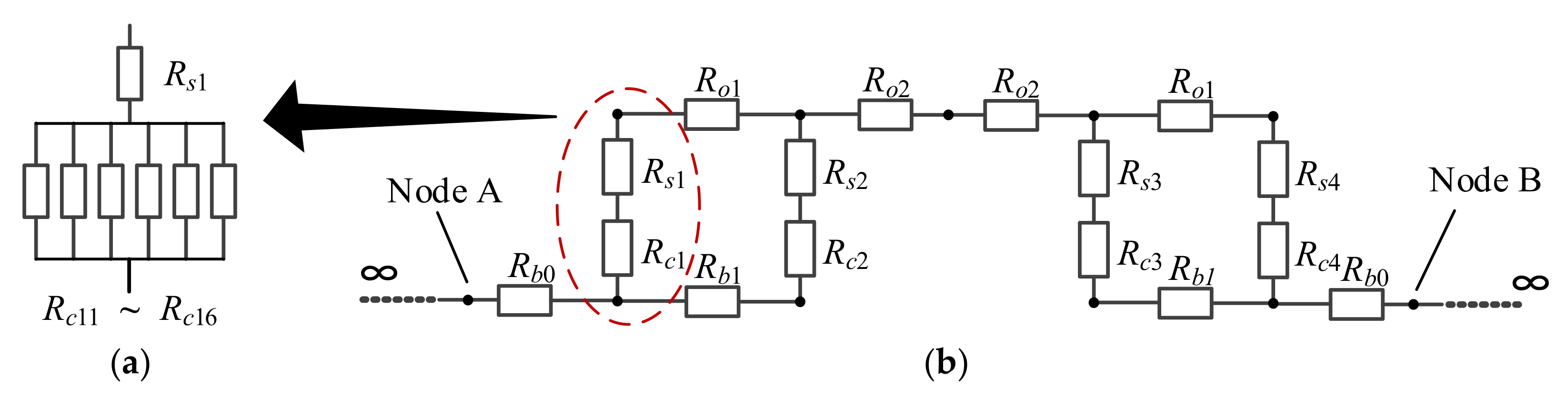
Section 2 establishes the equivalent circuit of the connection resistance of the compression connector.
Section 3 and
Section 4 develop models for determining the contact resistance and SE resistance, respectively.
Section 5 presents the numeric results and analysis.
Section 6 presents the experimental verification.
Section 7 concludes the paper.
6. Experimental Verification
The connection resistance of the compression connectors with five different cross sections were measured using IUXPower and a digital DC bridge. The compression connectors with 120, 150, 240, 500, and 630 mm
2 cross sections are shown in
Figure 17a.
Figure 17b shows the digital DC bridge, which can measure DC resistance and the measuring accuracy was ±0.01 μΩ.
Figure 17c shows the IUXPower, which can apply a stable AC current and measure the AC resistance. The measurement setup is shown in
Figure 17d. The measurement procedures are as follows:
- (1)
The IUXPower supplies a 50 Hz, 200 A AC current to measure loop AC resistance.
- (2)
The digital DC bridge was used to measure the DC resistance of the copper busbar. The measured copper busbar DC resistance was considered as equal to its AC resistance.
- (3)
The connection resistance was obtained by twice deducting the DC resistance of the copper busbar from the loop AC resistance.
To ensure the reliability of the experimental results, all experiments were conducted at least twice with a standard deviation less than 3%. The measurement results and calculation results based on the four methods are shown in
Table 8.
In the table, the results of the empirical formula were derived from a large number of measurements [
32]. The Hertz model ignores the microscopic contact between the conductors and the ferrule. The Greenwood model ignores the plastic deformation of the asperities. The Bahrami model considers the influence of microscopic contact, plastic deformation, and change of asperity summit radius, which results in a lower connection resistance. The average relative error of the four models is shown in
Table 9. Therefore, we can conclude that the Bahrami method can determine the connection resistance of the compression connector in the cable joint.
When the connection resistance is large, the local overheating can occur. Comparing the AC resistance of the cable conductor with the equal length of the ferrule, it was found that the resistance of the compression connector was much larger than that of the cable conductor. When the load was 300 A, the 120, 150, 240, 500, and 630 mm
2 cross section compression connector generated 24,375 J, 10,984 J, 4665 J, 2009 J, and 1134 J of additional heat per hour, respectively. The AC resistance and connection resistance of cable conductors are shown in
Table 10.


 ,
, 


