Abstract
The cooling load calculation of building envelopes is important for building design to realize building energy efficiency. A simplified way to predict the building envelope cooling loads is desperately needed to predict the cooling load of building envelopes with various construction layouts and to predict the energy-saving effect of various reconstruction measures for buildings. In light of this need a simplified calculation model for building envelope cooling loads is proposed in this paper. The model is based on dynamic hourly calculations using EnergyPlus. It considers almost all the thermal factors about the building envelope which may affect the building cooling load and it is studied by dimensional analysis. The equivalent window to wall ratio (EWWR) and building orientation factor are defined to study the building envelope cooling load. The cooling loads of twenty hypothetical buildings with various envelopes are predicated by EnergyPlus. With the results from EnergyPlus the simplified calculation model is developed by MATLAB. Then the newly developed model is validated by two typical actual buildings located in Central-South China. The results show the model is accurate enough to predict the building envelope cooling loads.
1. Introduction
The cooling load calculation of building envelopes is important for building design to realize building energy efficiency. The cooling load calculation is the first step for the design of building air conditioning systems because the transmission and distribution system, the size of the ultimate system and cooling resources, and the control strategies of the whole air conditioning system are all dependent on the cooling load [1,2,3].
Numerous researchers devote themselves to the study of building load calculations. For example, Sanza et al. introduced a new method for calculating conduction response factors in building multilayer constructions [4]. Cheng used deep learning algorithms to predict the short-term building cooling loads [5]. Ji and Xu estimated hourly cooling loads in commercial buildings using a thermal network model and electricity submetering data [6]. Hong and Gon proposed a cooling load prediction model considering the time-lag phenomenon based on multiple regression analysis [7]. Using extensive parametric energy simulations by Design Builder, Babak investigated the impact of geometric factors including building orientation, plan shape, plan depth, and window-to-wall ratio for the energy-efficiency of high-rise office buildings in three climate contexts [8]. From the reviewed literature, it is clear that there is little research focus on simplifying the prediction of building envelope cooling loads considering the thermal parameters, construction and orientation.
Traditionally the building cooling load is calculated based on the simplified calculation rule found in the Design Code for Heating Ventilation and Air Conditioning of Civil Buildings in China [9]. The code applies the cooling load factor method to calculate the building cooling load. It provides hourly outdoor cooling load calculation temperature (a simplified temperature including dynamics) of limited types of envelopes (i.e. 13 typical walls and seven typical roofs) in its appendix. When the building envelope is different from those typical constructions provided in the code we have to estimate the building envelope cooling load. Meanwhile for the dynamic characteristics of building cooling loads, it is suggested in the code that the building cooling load should be calculated using building energy simulation programs. In this paper, based on the hourly simulation data provided by the EnergyPlus program, a simplified calculation model will be proposed to predict the cooling load of building envelopes with various construction layouts.
The window to wall ratio (WWR) of walls with different orientations affects the building envelope cooling load in different ways [8]. Almost all the published studies are about the influence of a certain orientation WWR on the building energy consumption [10,11,12]. For example, Samah investigated the influence of WWR and window orientation on cooling, heating and total energy consumption [13]. Verbai analyzed the window size and window orientation to obtain a desired utilization factor for heating energy efficiency [14]. Wen concluded that window orientation significantly impact the optimal WWR configuration in Japan [15]. It is hard to apply the average WWR of the building envelope as a thermal parameter to calculate the building envelope cooling load or to assess the building envelope performance. In order to integrate the orientation of the window and WWR into a single parameter for the evaluation of building envelope performance, the equivalent window to wall ratio (EWWR) will be defined in this paper.
In addition, the building orientation also plays an important role in the calculation of envelope cooling loads [16]. The heat gain induced by the building envelope depends upon the solar radiation on various building surfaces. A lot of research has elaborated on the influence of building orientation on building energy consumption in different regions [17,18,19]. Few studies present a detailed factor to show how the orientation influences the building envelope cooling load. In the paper the building orientation factor is established. It is based on the building orientation and length to width ratio and it is applied to study the influence of building orientation on building envelope cooling load.
A simplified calculation model of building envelope cooling load is set up with the comprehensive heat transfer coefficient of building envelope (Kc). Kc takes into account almost all the thermal factors of the building envelope which may decide the building cooling load. The function between Kc and all the factors will be analyzed by dimensional analysis. Twenty hypothetical buildings are selected to study the parameter Kc. EnergyPlus is applied in the paper to calculate the building envelope cooling load, for it uses the heat balance algorithm to calculated the cooling load which is proved to be efficient and accurate [20,21]. Based on the results from EnergyPlus a model of Kc is established by Matlab. Then the simplified calculation model of building envelope cooling load is established with Kc. The study will provide a new way to study the building envelope cooling loads and to evaluate the building envelope energy efficiency.
2. Methodology
2.1. Objective
In order to study the cooling load of building envelopes, twenty hypothetical buildings with typical characteristics in the Chang-zhu-tan area of Central-South China are set up as the study cases. The figure of all the buildings are shown in Table 1. The buildings face towards the south. All the basic information about the building envelopes is listed in Table 2. The cooling load of the building envelopes is calculated by EnergyPlus (version 8.4) with dynamic hourly simulation. The simplified calculation models are based on the results of building energy consumption simulation provided by EnergyPlus.

Table 1.
Figure of the buildings.
Table 2.
Basic parameters about the building envelope of the twenty hypothetical buildings.
2.2. The Calculation of the Building Envelope Cooling Load
The cooling load of the building includes the cooling load induced by indoor heat gain, fresh air heat gain and building envelope heat gain. Indoor heat gain and fresh air heat gain depend on building indoor occupants and equipment. They are irregular and vary from one building to another, but it is easy to estimate them according to the function of the building. Building envelope heat gain depends on the building envelope and outdoor climate. It always requires accurate calculation. This paper mainly studies the building envelope cooling load.
According to the Chinese design code [9] the cooling load induced by building envelope can be calculated using Equations (1) and (2):
in which CLW(τ), CLr(τ) and CLg(τ) are the hourly cooling loads induced by heat transfer from external walls, external roofs and external windows, respectively, W. Kw, Kr and Kg are the heat transfer coefficients of external walls, roofs and windows, respectively, W/(m2·K). They are the reciprocal of the envelope thermal resistance at steady state. Aw, Ar and Ag are the areas of the external walls, roofs and windows, respectively, m2. to,w, to,r and to,g are the simplified hourly outdoor cooling load calculation temperatures of the external walls, roofs and windows, respectively, °C. The temperature is simplified based on the harmonic method and the transfer function method to calculate the building cooling load. The dynamics are included in the temperatures. They depend on the solar radiation intensity, building orientation, solar radiation absorption coefficient and thermodynamic performance of the envelope. tin is the indoor temperature, °C. CLg,s(τ) is the hourly cooling load induced by the solar radiation heat gain from the window, W. Cg,s is the solar radiation cooling load coefficient of standard glass without shade. Csd is the integrated shading coefficient of external windows. Cout,sd and Cin,sd are the correction coefficient of outside and inside window shades, respectively. Cg is the correction coefficient of glass. DJmax is the max index of summer solar radiation heat gain. Ag is the net external glass area, m2.
CLen(τ) is the building envelope hourly cooling load. The peak value of CLen(τ) is used for the sizing of air conditioning systems and it is short for cooling load in this paper. Equation (2) shows that the envelope cooling load CLen mainly depends on the solar radiation intensity and various building envelope parameters. It can be simplified as Equation (3):
where CLen is the cooling load of the building envelope, W/m2. Kc is the comprehensive heat transfer coefficient of the building envelope, which considers all the factors about building envelope mentioned in Equation (1) (W/(m2·K)). It is an equivalent coefficient that includes delays and not just the pure steady state. ΔT is the difference between the indoor temperature and outdoor temperature on a summer design day, K. At is the total building external envelope area including external roof areas, wall areas and glass areas, in m2.
2.3. Dimensional Analysis of Kc
According to the analysis above, it can be known that the comprehensive heat transfer coefficient of a building envelope Kc depends on the envelope thermal parameters such as heat transfer coefficient of the external walls (Kw), roofs (Kr) and windows (Kg), the heat storage coefficient of the external walls and roofs (S), solar radiation absorption coefficient of the outside surfaces of external walls (aw) and roofs (ar), and the window solar heat gain coefficient (SHGC). It is also influenced by area parameters such as building external envelope area (At), building construction area (Ac), external roof area (Ar), WWR and so on. Additionally it relies on outdoor climate factors such as the solar radiation intensity and the building orientation. Among these factors the solar radiation intensity is hard to determine for it depends on the location of the building. All the buildings in the paper are assumed to be located in the Chang-Zhu-Tan area, in Central South China. The window frame is neglected in the paper to simplify the calculation model, so the heat transfer coefficient of the window is simplified as the heat transfer coefficient of the glass. The external window shade coefficient depends on its shade form as well as the orientation of the shade. Its effect on the cooling load is also a complicated problem. It will be further studied in future research so it is not considered in this paper. Building orientation is neglected in the dimensional analysis and it will be studied in the next part of the paper.
Based on the dimensional theory [22], the relationship between the comprehensive heat transfer coefficient of building envelope and all the governing factors mentioned above can be described by Equation (4):
in which Kc is the comprehensive heat transfer coefficient of the building envelope, W/(m2·K). ΔT is the temperature difference between the indoor temperature and outdoor temperature on a summer design day, K.
Buckingham’s theorem is employed here to develop the correlation. The comprehensive heat transfer coefficient of external walls (Kc), building external envelope area (At) and temperature difference between the indoor temperature and outdoor temperature on a summer design day (ΔT) are chosen as the repeated parameters, with three fundamental dimensions, which are temperature, heat and length. The ten dimensionless parameters can be defined as Equation (5):
The results of Equation (5) are shown as Equation (6):
The results of Equation (6) show that:
(1) π1, π2 and π3 are the dimensionless factors about the heat transfer coefficient of building envelope.
(2) π4 = At/Ac is the building external envelope area per building construction area. π5 = Ar/At is the ratio of the building external roof area to the building external envelope area. Both dimensionless factors π4 and π5 are significant factors for building envelope cooling loads. They can be combined as a new dimensionless factor formulated by Equation (7):
in which n is the storey of the building. Bsf is defined as the building shape factor.
(3) π6 = S/Kw is the thermal inertia index D. D is considered as the area weighed thermal inertia index of the external walla and roofa, it can be calculated using Equation (8):
in which Dr and Dw is thermal inertia index of the external wall and roof, respectively.
According to the dimensional theory the relationship between Kc and other factors can be shown as:
2.4. Equivalent Window to Wall Ratio (EWWR)
The WWR has a significant effect on the building cooling load. The WWR with different orientations affects the heating and cooling energy consumption in different ways [23,24,25]. It is unreasonable to take an average WWR to calculate the building envelope cooling load. To solve this problem, the equivalent window to wall ratio (EWWR) is defined in the paper. It is considered that a building that has the same EWWR would have the same solar radiation heat gain from windows on a summer design day.
The heat gained from all the windows can be calculated by Equation (10):
in which Qg is the total heat gain from all the external windows on a summer design day, KJ. Qg,S', Qg,N', Qg,E' and Qg,W' are the heat gains from the external approximately south, north, east and west facing windows, KJ. Qg includes the solar heat gain and heat gain induced by temperature difference. The results of the EnergyPlus show that the windows with different orientation have little effect in the heat gain induced by indoor and outdoor temperature differences, so only the solar heat gain is considered in Equation (10).
The solar radiation heat gain of the south facing windows is considered as the reference, so Equation (10) can be rewritten as Equation (11):
in which Ag,e is the equivalent area of all the external windows, m2. qg,S is solar radiation heat gain of external south facing windows on a summer design day, KJ/m2. Ag,S', Ag,N', Ag,E' and Ag,W' are the areas of the external approximately south, north, east and west facing windows, respectively, m2. qg,S′, qg,N′, qg,E′ and qg,W′ are the heat gained from the external approximately south, north, east and west facing windows, respectively, KJ/m2. λg,S', λg,N', λg,E' and λg,W' are the equivalent coefficients of the external approximately south, north, east and west facing windows, respectively. They are defined as Equation (12):
Based on the equivalent coefficient of the external windows the EWWR is defined as Equation (13):
where Aw is the total external wall area, including the windows. EWWR will change with the building orientation.
In order to get a more accurate calculation model, WWR is replaced by EWWR in Equation (9) and it is rewritten as Equation (14):
2.5. The Building Orientation Factor
The impact of building orientation factor on building cooling load is complex and it is hard to obtain an accurate model if it is considered in the dimensionless analysis. In order to get the calculation model by Equation (14) all the buildings is assumed to be facing south. Then in practical application, if the building is not facing the south, the calculation model would be corrected by the building orientation factor.
Building orientation would impact the building envelope cooling load for the reason that the surface temperature and solar radiation heat gain of the walls change along with the orientation. Actually it depends on the incident solar radiation rate of different facing walls. Accumulative incident solar radiation of the south faced wall on the summer design day is considered as the reference to calculate the equivalent factor of building external walls:
in which λw,S', λw,N', λw,E' and λw,W' are the equivalent factora of the external approximately south, north, east and west facing walls, respectively. IS′, IN′, IE′ and IW′ are the accumulative incident solar radiation rate on the summer design day of external approximately south, north, east and west facing walls, respectively, (J/m2). IS is the accumulative incident solar radiation rate of the south facing wall, (J/m2).
Based on equivalent factor of the walls, the building orientation factor is defined as Equation (16):
in which C is the building orientation factor. θ is the building length to width ratio. λw,S, λw,N, λw,E and λw,W are the equivalent factor of external south, north, east and west facing envelopes, respectively. The denominator of Equation (16) is the incident solar radiation rate obtained from the south faced building and the numerator is the incident solar radiation rate obtained from a building with any orientation. The equation shows that when the building is south facing, C = 1. When the building is non-south faced, C ≠ 1.
As it is defined in Part 2.4 that EWWR would change along with the building orientation, the window heat gain should not be corrected again by the building orientation factor C. When the building orientation factor C is taken into account, Equation (14) can be reformulated as Equation (17):
3. Results and Discussion
3.1. Equivalent Window to Wall Ratio (EWWR)
3.1.1. Equivalent Coefficient of External Windows with Different Orientation
The incident solar radiation rate of the external south, north, east and west facing walls on summer design day in Chang-Zhu-Tan area can be gotten from the climate file and the data is shown in Figure 1.
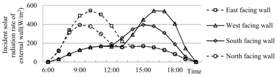
Figure 1.
The hourly incident solar radiation rate of external south, north, east and west facing walls on summer design day.
It is shown that the incident solar radiation of an east and north facing wall mainly happens in the morning, while for the south and west facing walls it mainly happens in the afternoon. The incident solar radiation rate of each facing wall depends on the location of the building on the Earth and the location of the Sun in relation to the Earth. The Sun rises from the north-east and sets to the south-west in the Chang-zhu-tan area of China.
The equivalent coefficient of the external approximately south, north, east and west facing windows λg,S', λg,N', λg,E' and λg,W' can be obtained by Equation (12) with the data from climate files. Figure 2 shows the equivalent coefficients of three types of window (i.e. single 3 mm clear glazing window, single 6 mm clear glazing window and double 6 mm glazing window with 9 mm air gap) in the Chang-Zhu-Tan area. It is shown that window equivalent coefficient is symmetrical along the south to north axis. The south and north facing windows have minimum equivalent coefficients while the east and west facing windows have the maximum equivalent coefficients. The data in Figure 2 indicates that there is little difference among the equivalent coefficients of the three types of windows. Values for double glazing windows with different air type and thickness as well as the low-E windows have all been calculated, and the results show that the equivalent coefficients of the windows are similar to that of the 6 + 9A + 6 double glazing window.
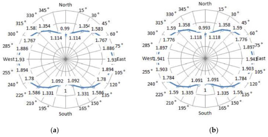
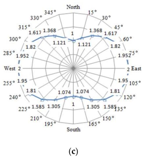
Figure 2.
Equivalent coefficient of different windows in the Chang-Zhu-Tan area.(a) Single clear glazing 3 mm window; (b) Single clear glazing 6mm window; (c) double 6 mm glazing window with 9 mm air gap (6 + 9A + 6).
3.1.2. Analysis of EWWR
If the building is a cuboid and its window area is symmetrical, that is Ag,S' = Ag,N' and Ag,E' = Ag,W', then Equation (17) can be expressed as Equation (18):
The window equivalent coefficient of buildings facing south by west and south by east can be obtained from Figure 2. It can be concluded that:
(1) The buildings facing south by west and south by east with the same angle would have the same (λg,S' + λg,N') and (λg,E' + λg,W'). It is indicated that for the same building, when it faces south by west and south by east with the same angle, it would have the same EWWR and thus the same window solar heat gain.
(2) Buildings facing south by west 45° to south by east 45° (that is 135° to 225° in Figure 2) would have (λg,E' + λg,W') > (λg,S' + λg,N'). For example the building facing south has (λg,S + λg,N) = 2 and (λg,E + λg,W) = 4. Compared with a building with large approximately south or north facing windows, the building with large approximately east and west facing windows would have a greater EWWR and thus a larger cooling load.
3.2. The Building Orientation Factor C
3.2.1. Equivalent Coefficients of External Walls with Different Orientations
The equivalent coefficients of the external approximately south, north, east and west facing walls λw,S', λw,N', λw,E' and λw,W' can be obtained using Equation (15) and the results are shown in Figure 3. The equivalent factor of approximately east facing walls is symmetric with that of approximately west facing walls by axis north-south.
Figure 3.
Equivalent factors of external walls in the Chang-Zhu-Tan area.
3.2.2. Analysis of Building Orientation Factor C
It can be obtained by Figure 3 that λw,S = 1, λw,N = 0.947 and λw,E = λw,W = 1.73, and Equation (16) can be transformed into Equation (19):
(1) When the building faces south, it has C = 1. As shown in Figure 3 it can be known that (λw,S' + λw,N') > (λw,S + λw,N) = 1.947 and (λw,E' + λw,W') <(λw,E + λw,W) = 3.46, meanwhile the building length to width ratio is θ ≥ 1. It can be concluded that the south facing building has the minimum building orientation factor C = 1. The non-south facing buildings would have C > 1. This means that a similar building would have a minimum cooling load when it faces south rather than other orientations. As a result south is the most reasonable orientation for buildings located in the Chang-zhu-tan area.
(2) The data in Figure 3 shows that the buildings facing south by west and south by east with the same angle will have almost the same (λw,S + λw,N') and (λw,E' + λw,W'). According to Equation (19), a building facing south by west and south by east with the same angle would have the same C.
(3) Taking the derivation of Equation (19) with respect to θ it can be obtained that:
When the building faces south, as (λw,S + λw,N) = 1.947 and (λw,E + λw,W) = 3.46 (Figure 3), so C′ = 0. When the building faces south by east or south by west C′ > 0. For the reason that (λw,S′ + λw,N′) > 1.947 and (λw,S′ + λw,N) increases with the mounting angle while (λw,E′ + λw,W′) < 3.46 and (λw,E′ + λw,W′) decreases with the mounting angle. As C′ > 0 it can be concluded that the building orientation factor C increases with the mounting building length to width ratio θ. It means that the orientation of the building will have more significant effect on building envelope cooling load when it has a larger θ.
3.3. The Simplified Calculation Model of Building Envelope Cooling Loads
3.3.1. The Comprehensive Heat Transfer Coefficient of Building Envelope
Twenty buildings (Table 1) with various external wall, roof and window construction layouts which formed about 280 samples are simulated by EnergyPlus to get their envelope cooling loads. The external walls, roofs and windows are the main subject in the paper, so the cooling load from the ground floor is neglected by setting its construction from downside to upside as mineral wool 100 mm + strength concrete 100 mm + cement + gravel 20 mm. Its heat transfer coefficient is K = 0.446. All the 280 samples are assumed built on the ground and with the same ground floor construction. For buildings with basement opened to outdoors, the roof of the basement (i.e. the floor of first storey) is approximated as an external wall in the calculations. With the simulation results Equation (14) is solved by MATLAB and the results is shown as follows (R = 0.9):
Equation (3) can be converted into Equation (22):
in which CLen/At is defined as the building cooling load per building envelope area, W/m2.
The building cooling loads per building envelope area calculated by EnergyPlus (pseudo true value) and the regression results are shown in Figure 4. It is indicated that Equation (22) is not so perfect for all the buildings because part of the buildings (i.e. buildings 1–15 on the left of vertical dotted line) have quite large errors. All the data were carefully analyzed and it is found that building 16–20 (Table 1) with building shape factor Bsf ≥ 0.866 (Table 2) have different rules compared to other buildings. Then all the buildings are classified into two groups, namely buildings with Bsf ≥ 0.866 and Bsf < 0.866. The boundary value of 0.866 is obtained by the study of the twenty hypothetical buildings. It may not be the most accurate value because of the limited number of samples. Also it may not be relevant for all the buildings. At the same time the twenty buildings have typical shapes and these buildings can be combined freely to form the majority of building types in practice. The boundary value for building grouping is proved to be reasonable for the building shapes studied in the paper.
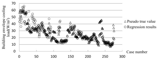
Figure 4.
Pseudo true value from EnergyPlus and regression results of building envelope cooling load for all the buildings.
3.3.2. Envelope Cooling Load of Buildings with Bsf < 0.866
About 160 samples of buildings 1–15 (Table 1) with Bsf < 0.866 has been recalculated by MATLAB. The function of Kc is shown in Equation (23) (R = 0.9764):
Equation (3) can be formulated as:
The building envelope cooling loads per building envelope area CLen/At calculated by EnergyPlus (pseudo true value) and Equation (24) is shown in Figure 5. It is indicated that the building envelope cooling load calculated by EnergyPlus is highly consistent with the results from Equation (24). It can be concluded that the dimensional equation about Kc established for the buildings with Bsf < 0.866 is relatively accurate.
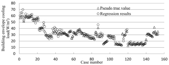
Figure 5.
Pseudo true value from EnergyPlus and regression results of building envelope cooling load for buildings with Bsf < 0.866.
The building envelope cooling load per construction area CLen/Ac can be deduced by Equation (24):
where Ac is the building construction area, Ar is the building external roof area and n is the storey of the building. Equation (25) shows that the effect of each factor on the cooling load is different. It can be indicated that EWWR and Kg are the most important factors for building envelope cooling loads. Both EWWR and Kg are factors about windows. The reason is that the heat transfer coefficient of windows is always much larger than that of walls and roofs, thus the window would lead to larger heat gain induced by heat transfer. On the other hand, the solar radiation heat gain induced by windows is also quite large, so for these buildings the EWWR should be strictly controlled. After EWWR and Kg, At/Ac is the third most important factor for building envelope cooling loads. A larger At/Ac means a larger envelope area per construction area and thus larger heat gain from outside. As the buildings with Bsf <0.866 have a mirror Ar/At (Table 2), the effect of solar radiation absorption coefficient ar on cooling load is less than that of aw. It also can be concluded that the effect of aw and ar on the cooling load is larger than that of Kw and Kr. Therefore the use of external walls and roofs with low surface solar radiation absorption coefficient will be an effective way to reduce building energy consumption in summer. The relation between thermal inertia index D and envelope cooling load is delicate. The cooling load referred in the paper is the peak value of hourly cooling loads. Envelope cooling load includes cooling load induced by heat transfer from the envelope and cooling load induced by solar radiation heat gain from the windows. The appearance time of the peak value of cooling load induced by heat transfer from the envelope depends on the envelope thermal inertia index D, while the appearance time of the peak value of cooling load induced by solar radiation heat gain depends on WWR and the orientation of the windows, so the peak value depends on the ratio of heat transfer heat gain by the envelope to the solar radiation heat gain by windows. On the one hand these buildings have a mirror Ar/At, while on the other hand the buildings have quite different EWWR, ranging from 0.316 to 0.933 (Table 2). Considering all the factors it can be concluded that the envelope cooling load of buildings with Bsf <0.866 is proportional to the thermal inertia index D.
3.3.3. Envelope Cooling Load of Buildings with Bsf ≥ 0.866
About 120 samples of buildings 16–20 (Table 1) with Bsf ≥ 0.866 were recalculated by MATLAB. The function of Kc is shown in Equation (26) (R = 0.9562). Equation (3) can be formulated as:
CLen/At calculated by EnergyPlus (pseudo true value) and Equation (27) are shown in Figure 6. The deviations between the results from EnergyPlus and Equation (27) are acceptable. It can be concluded that the dimensional equation about Kc established for the buildings with Bsf ≥ 0.866 is relatively accurate.
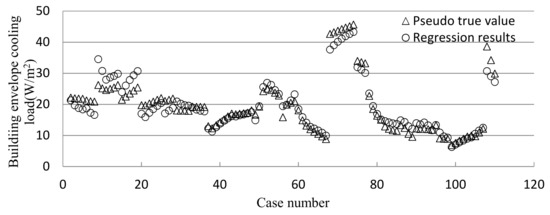
Figure 6.
Pseudo true value from EnergyPlus and regression results of building envelope cooling loads for buildings with Bsf ≥ 0.866.
The building envelope cooling load per construction area CLen/Ac can be deduced by Equation (27):
Equation (28) shows that CLen/Ac is proportional to Kw, Kr, Kg, At/Ac, n, aw, ar, EWWR, ΔT and inversely proportional to (1 − SHGC) and D. Compared with Equation. (25) for buildings with Bsf < 0.866, Equation (28) for buildings with Bsf ≥ 0.866 is quite different. The factor (1 − SHGC) replaced EWWR as the most important factor for building envelope cooling loads. Therefore, shading for windows should be an effective way to reduce the cooling load for these buildings. After (1 − SHGC), Kg, Ar/At and D are the second most important factors for the cooling load calculation. It also can be concluded that the effect of solar radiation absorption coefficient ar on cooling load is more than that of aw. Factors Kg, Ar/At, D and ar are all about the external roof. The buildings with Bsf ≥ 0.866 have larger Ar/At than other buildings, so the factors about the external roof all have a great effect on the cooling load. For these buildings they should focus on the energy efficiency of external roofs.
3.3.4. The Simplified Calculation Model for Building Envelope Cooling Load
Equations (25) and (28) are for buildings facing south. The calculation model for buildings with any orientation should be calculated with building orientation factor as shown in Equation (17). Then Equations (25) and (28) can be formulated as Equations (29) and (30), respectively. When Bsf < 0.866:
If Bsf ≥ 0.866,
Equations (29) and (30) are the simplified calculation models for building envelope cooling load, which can be applied for buildings with any orientation. These equations are suitable for buildings located in the Chang-Zhu-Tan area, which located in Central-South China. Equations for buildings located in other places should be similar to Equations (29) and (30) but may have different indexes for each parameter. They can be developed with the same analysis methods described in the paper. Equations (29) and (30) are validated by two practical buildings as follows.
4. Validation of the Simplified Calculation Models
Two typical actual buildings, namely Jianglu Hospital (Figure 7a) and Tongfeng Plaza (Figure 7b), located in the Chang-Zhu-Tan area are selected to validate the simplified calculation models.
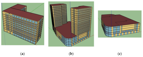
Figure 7.
Practical buildings for validating the simplified calculation model. (a) Jianglu Hospital; (b) Tongfeng Plaza; (c) shopping center of Tongfeng Plaza.
The envelope cooling loads of both buildings are predicted by EnergyPlus and the simplified calculation models simultaneously.
4.1. Basic Information about Jianglu Hospital and Tongfeng Plaza
The main building of Jianglu Hospital faces south. Tongfeng Plaza includes a shopping center, hotel and offices. The shopping center faces south by west 30°. The composition of the external walls, external roofs and windows of these buildings are shown in Table 3.
Table 3.
Envelope composition of Jianglu Hospital and Tongfeng Plaza.
According to the composition of the buildings, the heat transfer coefficient of external walls, roofs and windows (Kw, Kr, Kg) are the reciprocal of the envelope thermal resistance at steady state. The solar radiation absorption coefficients of the envelope (aw, ar) and the solar heat gain coefficients of windows (SHGC) are obtained from the design handbook [26]. The building information, including building total external envelope area (At), total construction area (Ac), roof area (Ar) and storeys of the buildings (n) are all shown in Table 4.
Table 4.
Thermodynamic parameters for the building envelopes of Jianglu Hospital and Tongfeng Plaza.
4.2. Validation Results
The indoor temperatures of these buildings are all set as 26 °C and the outdoor design temperature for air conditioning in the Chang-Zhu-Tan area is 34.9 °C.
4.2.1. Results for Jianglu Hospital
Its window to wall ratio is WWR = 0.368. By counting its window area and window orientation, its equivalent window to wall ratio can be obtained by Equation (13) and the result is EWWR = 0.504. According to its envelope composition the thermal inertia index of the external walls and roof can be obtained from the design handbook [26]. Then the area weighed thermal inertia index of the external walls and roof can be calculated by Equation (8) and the result is D = 2.46 (Table 4).
The building shape factor of Jianglu Hospital should be known to decide the cooling load calculation model. According to Equation (7) the Bsf of Jianglu Hospital is:
Bsf = 0.289 < 0.866
Therefore Equation (29) is selected to predict the envelope cooling load of Jianglu Hospital. It is shown in Figure 7a that Jianglu Hospital is not a cuboid but rather an "L" shaped building. Its floor plan is shown in Figure 8a. In order to apply Equation (29) to predict its envelope cooling load conveniently, the floor plan can be supposed as a rectangle (Figure 8b). Then part of the cooling load can be revised by building orientation factor C. The length to width ratio of the rear building is θ = 1.2.The building orientation factor C = 1.052 can be obtained by Equation (16). The actual envelope cooling load can be obtained as 17.54 W/m2. The envelope cooling load of Jianglu Hospital calculated by EnergyPlus is 18.2W/m2, i.e. 3.76% more than that predicted by Equation (29).
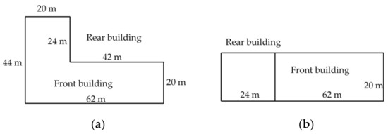
Figure 8.
The plan (a) and deformed plan (b) of Jianglu Hospital.
4.2.2. Results of Tongfeng Plaza
Tongfeng Plaza includes a shopping center, offices and hotel. The envelope cooling load of these buildings should be calculated separately. First is the shopping center. Its window to wall ratio is WWR = 0.281. Its EWWR = 0.437, D = 3.88, θ = 1.42 and C = 1.103 are obtained in the same way as Jianglu Hospital. According to Equation (7) the Bsf of the shopping center is:
Bsf = 1.256 > 0.866
Therefore Equation (30) is selected to predict the envelope cooling load of the shopping center and the result is 7.39 W/m2. Actually the envelope cooling load of 7.39 W/m2 is for the shopping center whose roof is completely exposed to the Sun, so the figure of the shopping center applied in EnergyPlus should be under the same situation as shown in Figure 6c. The envelope cooling load of the shopping center (Figure 7c) calculated by EnergyPlus is 7.18 W/m2. The results show that the envelope cooling load of the shopping center predicted by Equation (30) is 2.84% larger than that of EnergyPlus.
Second is the office building. Its window to wall ratio is WWR = 0.204. Its EWWR = 0.29, D = 4.07, θ = 1.59 and C = 1.11. According to Equation (7) the Bsf of the office building is:
Bsf = 0.202 < 0.866
Therefore Equation. (29) is selected to predict the envelope cooling load of the office building and its result is 10.84W/m2. The envelope cooling load of the office building calculated by EnergyPlus is 11.3W/m2. It is indicated that the envelope cooling load of the shopping center predicted by Equation (29) is 4.24% less than that of EnergyPlus.
Third is the hotel. Its window to wall ratio is WWR = 0.25. Its EWWR = 0.378, D = 4.06, θ = 1.266 and C = 1.09. According to Equation (7) the Bsf of the hotel is:
Bsf = 0.256 < 0.866
Therefore Equation (30) is selected to predict the envelope cooling load of the office building and its result is 12.01W/m2. The result of EnergyPlus is 12.36W/m2, i.e. 3.5% more than the value predicted by Equation (30).
Compared with the envelope cooling load calculated by EnergyPlus, the deviation of results from the simplified calculation model are all within 5% for both of the practical buildings. The envelope cooling load of these buildings are also estimated by the design code [9] and the results are about 20% larger than that obtained from EnergyPlus. That is because the calculation methods applied in EnergyPlus and design code are different. The cooling load factor method used in the code for envelope cooling load calculations is based on the harmonic method and transfer function method [9], while EnergyPlus uses the heat balance algorithm to calculate the cooling load. Different methods would lead to a certain different result [21]. Generally speaking, it can be concluded that Equations (29) and (30) as the simplified calculation model for building envelope cooling loads is accurate enough to predict the building envelope cooling loads.
5. Conclusions
A simplified calculation model for building envelope cooling loads has been present in this paper. It is based on dimensional analysis and dynamic hourly calculation results from EnergyPlus. The model has been validated by two typical practical buildings located in Central-South China. In addition, the new concept of EWWR and building orientation factor have been defined in the paper. The conclusions are summarized as follows:
- (1)
- EWWR is more reasonable than traditional WWR in building envelope cooling load calculation and building envelope energy efficiency evaluation because it takes window orientation into account. The minimal EWWR means the minimal solar radiation heat gain by external windows.
- (2)
- Building orientation factor C depends on the building orientation and its length to width ratio. A building located in Central-South China may have a minimum cooling load when it faces south. C increases with the mounting building length to width ratio θ. It means that the orientation of the building will have a more significant effect on building envelope cooling load when it has a larger θ.
- (3)
- The results indicate that the simplified calculation model proposed in the paper is accurate enough to predict building envelope cooling loads. The study shows that buildings can be classified into two types in accordance with their shape. One has the building shape factor Bsf < 0.866 and the other has Bsf ≥ 0.866. They have different models for building envelope cooling load calculation and different levels of building envelope energy efficiency. The boundary value of shape factor 0.866 may not be the most accurate value because of the limited samples used in the paper. It also may not be relevant for all buildings. It may change after further study of more buildings. At present the boundary value 0.866 is a basic and important reference value that can be used for grouping buildings to realize energy efficiency improvements and it can also serve as a reference for further improvement.
The paper provides a new way for the air conditioning designers to predict the cooling load of building envelopes with various construction layouts very conveniently. It may also be an effective and quick way to predict the energy-saving effect of various reconstruction measures for buildings.
Author Contributions
G. G. conceived and designed the research; P. W. performed the calculation; B. Q. provided some basic information related to the research; Y. Z. and P. W. analyzed the data; P. W. wrote the paper.
Funding
This work was funded by the National Key Technology Support Program by Grant number [2015BAJ03B00]; National Natural Science Foundation of China by Grant number [51378186]; Zhejiang Province Natural Science Foundation by Grant number [LQ14E080003].
Conflicts of Interest
The authors declare no conflicts of interest.
References
- Wang, Z.; Srinivasan, R.S. A review of artificial intelligence based building energy use prediction: Contrasting the capabilities of single and ensemble prediction models. Renew. Sustain. Energy Reviews 2017, 75, 796–808. [Google Scholar] [CrossRef]
- Wang, P.; Gong, G.; Wang, Y.; Li, L. Thermodynamic investigation of building integrated energy efficiency for building retrofit. Energy Build. 2014, 77, 139–148. [Google Scholar] [CrossRef]
- Mao, N.; Pan, D.; Song, M. Operating optimization for improved energy consumption of a TAC system affected by nighttime thermal loads of building envelopes. Energy 2017, 133, 491–501. [Google Scholar] [CrossRef]
- Pérez, J.; Chicote, M.; Díez, F.; Gómez, E. A new method for calculating conduction response factors for multilayer constructions based on frequency-Domain spline interpolation (FDSI) and asymptotic analysis. Energy Build. 2017, 148, 280–297. [Google Scholar] [CrossRef]
- Cheng, F.; Fu, X.; Zhao, Y. A short-term building cooling load prediction method using deep learning algorithms. Appl. Energy 2017, 195, 222–233. [Google Scholar]
- Ji, Y.; Xu, P.; Duan, P.; Lu, X. Estimating hourly cooling load in commercial buildings using a thermal network model and electricity submetering data. Appl. Energy 2016, 169, 309–323. [Google Scholar] [CrossRef]
- Lim, H.; Kim, G. Prediction model of Cooling Load considering time-lag for preemptive action in buildings. Energy Build. 2017, 151, 53–65. [Google Scholar] [CrossRef]
- Raji, B.; Tenpierik, M.; van den Dobbelsteen, A.A.J.F. Early-Stage Design Considerations for the Energy-Efficiency of High-Rise Office Buildings. Sustainability 2017, 9, 623. [Google Scholar] [CrossRef]
- China’s housing ministry. Design code for Heating Ventilation and Air conditioning of Civil buildings in China (GB50736-2012); Architecture & Building Press: Beijing, China, 21 January 2012. (in Chinese)
- Ghose, A.; McLaren, S.J.; Dowdell, D. Environmental assessment of deep energy refurbishment for energy efficiency-case study of an office building in New Zealand. Build. Environ. 2017, 117, 274–287. [Google Scholar] [CrossRef]
- Gong, X.; Akashi, Y.; Sumiyoshi, D. Optimization of passive design measures for residential buildings in different Chinese areas. Build. Environ. 2012, 58, 46–57. [Google Scholar] [CrossRef]
- Kazanasmaz, T.; Grobe, L.O.; Bauer, C.; Krehel, M.; Wittkopf, S. Three approaches to optimize optical properties and size of a South-facing window for spatial Daylight Autonomy. Build. Environ. 2017, 102, 243–256. [Google Scholar] [CrossRef]
- Alghoul, S.K.; Rijabo, H.G.; Mashena, M.E. Energy consumption in buildings: A correlation for the influence of window to wall ratio and window orientation in Tripoli, Libya. J. Build. Eng. 2017, 11, 82–86. [Google Scholar] [CrossRef]
- Verbai, Z.; Csáky, I.; Kalmár, F. Balance point temperature for heating as a function of glazing orientation and room time constant. Energy Build. 2017, 135, 1–9. [Google Scholar] [CrossRef]
- Wen, L.; Hiyama, K.; Koganei, M. A method for creating maps of recommended window-to-wall ratios to assign appropriate default values in design performance modeling: A case study of a typical office building in Japan. Energy Build. 2017, 145, 304–317. [Google Scholar] [CrossRef]
- Liu, L.; Wu, D.; Li, X. Effect of geometric factors on the energy performance of high-rise office towers in Tianjin, China. Build. Simul. 2017, 10, 625–641. [Google Scholar] [CrossRef]
- Dutta, A.; Samanta, A.; Neogi, S. Influence of orientation and the impact of external window shading on building thermal performance in tropical climate. Energy Build. 2017, 139, 680–689. [Google Scholar] [CrossRef]
- Kontoleon, K.J.; Eumorfopoulou, E.A. The influence of wall orientation and exterior surface solar absorption on time lag and decrement factor in the Greek region. Renew Energy 2008, 33, 1652–1664. [Google Scholar] [CrossRef]
- Valladares-Rendón, L.G.; Schmid, G.; Lo, S.-L. Review on energy savings by solar control techniques and optimal building orientation for the strategic placement of facade shading systems. Energy Build. 2017, 140, 458–479. [Google Scholar] [CrossRef]
- Ahmad, M.W.; Mourshed, M.; Yuce, B. Computational intelligence techniques for HVAC systems: A review. Build. Simul. 2016, 9, 359–398. [Google Scholar] [CrossRef]
- Zhu, D.D.; Yan, D.; Hong, T.; Wang, C. Comparison of Building Energy Simulation Programs: DeST. EnergyPlus and DOE-2. Build. Sci. 2012, 28, 213–222. (In Chinese) [Google Scholar]
- Tan, Q. Dementional Analysis; China Science and Technology Press: HeFei, China, August 2015. (In Chinese) [Google Scholar]
- Chen, Z.; He, J.; Sun, W. Study on Window-wall Ratio in Different Orientations for Office Buildings in Hot Summer and Cold Winter Zone. Build. Sci. 2009, 6, 80–85. (In Chinese) [Google Scholar]
- Jian, Y.; Jiang, Y. Influence of window-wall ratio on annual energy consumption for heating and air conditioning in residential buildings. Heat. Vent. Air Cond. 2006, 6, 1–5. Available online: http://en.cnki.com.cn/Article_en/CJFDTOTAL-NTKT200606000.htm (accessed on 27 June 2018). (In Chinese).
- Zhao, Y.; Diao, N. Influence of window–wall ratio and shape coefficient on the annual dynamic load of buildings. J. Shandong Jianzhu Univ. 2012, 6, 617–621. (In Chinese) [Google Scholar]
- Lu, Y. Practical design handbook for heating and air conditioning; Architecture & Building Press: Beijing, China, May 2008. (In Chinese) [Google Scholar]


© 2018 by the authors. Licensee MDPI, Basel, Switzerland. This article is an open access article distributed under the terms and conditions of the Creative Commons Attribution (CC BY) license (http://creativecommons.org/licenses/by/4.0/).