Review

The State of the Art of Topologies for Electric Springs

1
School of Electrical Engineering, Southeast University, 2 SiPaiLou, Nanjing 210096, China
2
Department of Industrial Engineering, University of Padova, 35131 Padova, Italy
*
Author to whom correspondence should be addressed.
These authors contributed equally to this work.
Energies 2018, 11(7), 1724; https://doi.org/10.3390/en11071724
Submission received: 9 May 2018 / Revised: 1 June 2018 / Accepted: 20 June 2018 / Published: 2 July 2018

Abstract

:
This paper aims to review the state of the art in topologies for electric springs (ESs) and their suitability for different applications in distributed power systems with sufficient power generation from renewable energy sources, especially at domestic households. Owing to the fact that there exist many kind of ESs, a comprehensive overview of single-phase ESs sequenced as ES-1, ES-2, ES-3 and other forms, three-phase ESs (TPESs) sequenced as TPES-1, TPES-2 etc., and direct current ES (DCES) sequenced as DCES-1, DCES-2, PVES is conducted. The originalities, advantages and disadvantages of each ES topology version are analyzed to propose its most suitable application. Besides, comparisons between ESs and traditional flexible alternating current transmission (FACTS) devices are addressed. Finally, conclusions and possible future research trends are pointed out.

1. Introduction

With the increasing proportion of power generation from intermittent renewable energy sources (RESs) injected to traditional power systems, stability issues have become more and more severe [1]. Electrical loads may suffer unsafe voltage and/or power fluctuations to some extent. The instability issue is mainly due to the centralized control adopted in the existing power system in which power generation depends on the load prediction. It is hard for power companies to predict and provide precise power to the power grid due to the distributed and intermittent natures of RESs. Flexible alternating current transmission (FACTS) devices [2,3], such as static var compensator (SVCs) [4], static var generators (SVGs) [5], static synchronous series compensators (SSSCs) [6], dynamic voltage restorers (DVRs) [7] and unified power flow controllers (UPFCs) [8] are commonly used to control voltage and/or power flow. However, most of them are for high-voltage or medium-voltage applications, and cannot be used for future smart grids with high penetration of distributed power generation, such as power generation from small wind turbine and roof photovoltaic (PV) panels [9]. Energy storage methods are an effective way to alleviate peak demands [10,11], but the needed devices are expensive. What’s more, the huge and frequent charging and/or discharging activities may reduce battery lifetime and system reliability. Electric springs (ESs) [12] were proposed for future distributed microgrids [13,14] as a new concept where load demand follows power generation dynamically [15]. In the ES theory, electrical loads are divided into two categories, namely critical loads (CLs) and non-critical loads (NCLs). It has been shown that the lifetime of storage devices and system reliability can be greatly enhanced by equipping existing power generation systems with ESs [16].
An overview of a typical distribution diagram with ESs in a single-phase AC power system is shown in Figure 1a [17]. The power generation block consists of a traditional AC power source injected by the power generation from RESs. Many load centers such as electrical devices in residential buildings are connected and located along the distribution line in the power grid. At each load center, one or more smart loads (SLs) are equipped in parallel with CLs to regulate the voltage of the point of common coupling (PCC). It is obviously seen that there is some distance between two neighboring load centers. A typical application circuit is shown in Figure 1b.
The characteristics of power grids with distribution lines make it possible for massive ESs to be distributed. What’s more, the stability of the total power grid will not be influenced by the failure of a single ES.
Since the ES was proposed as an emerging technology and demand side management solution for future smart grids [12], it could be interpreted as an electrical device having the ability to regulate the CL voltage and/or power while passing the fluctuations from the alternating current (AC) side to the NCLs. As a result, a mass of ESs are believed to be capable of dynamic power balancing. Besides, mass distribution of ESs is able to provide more efficient and reliable energy transfer [9]. The initial ES was proposed for AC applications so it is called ACES in this paper. In contrast, another type of ES which is used for direct current (DC) applications is called DCES. In this paper, the topologies and the applications of ESs are mainly discussed. For single-phase ESs, the versions are sequenced in this paper as ES-1 [12], ES-2 [18] and ES-3 [19]. The others are modified versions of ES-2 [20,21,22].
Regarding the three-phase ESs (TPESs), the basic topology is presented in [23] and [24], in which a transformer is adopted in each phase to isolate the TPES with its application circuits. It is believed that TPES could be one of the solutions for three-phase systems, i.e., unbalance and harmonics. Besides the basic topology of TPES, topologies named as Modified ES-2 and Isolated ES-2 can also be extended to their three-phase forms.
Calling on to this and other benefits such as issues of unbalanced three-phase, harmonics and synchronous, there is a growing interest in DC microgrids [25,26,27], especially for small-scale residential applications, i.e., roof PV systems. With the increasing number of such distributed generations (DGs) injected, the stability issue also occurs in DC microgrids where DCES could be introduced as a new kind of solution. In this paper, several kinds of topologies [28,29] are well illustrated and compared.
In detail, the paper is organized as follows: in Section 2, the initial configuration of single-phase ESs, designated as ES-1 and ES-2, are presented first and then other circuit topologies together with possible applications are proposed and discussed. Section 3 introduces several possible topologies and their applications of TPESs. It is revealed that some topologies of single-phase ESs can also be extended to three-phase systems. In Section 4, basic functionalities of DCES are explained first and then two typical topologies are selected for comparison, showing the advantages of the kind realized by DC/DC converters. In Section 5, general comparisons have been done between traditional FACTS devices and ACES. Finally, the concluding remarks and future trends are provided in Section 6. By convention, throughout the paper the time-variable quantities are denoted with lower case letters, the DC and rms quantities with upper case letters and the vector quantities with upper case letters topped by an arrow.

2. Single-Phase ESs

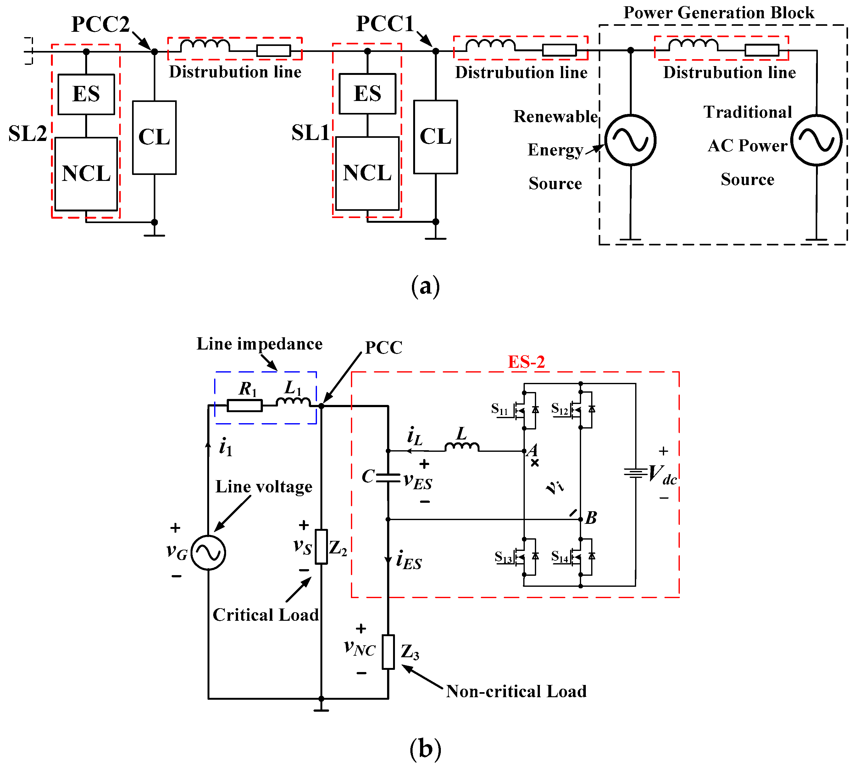
2.1. ES and Its Operating Principle

As explained in [12], the concept of ES derived from mechanical springs (MSs), which can be seen in Figure 2a according to the duality principle. The Hook’s law for an ideal mechanical spring is expressed as:
F = k Δ x
where F is mechanical force, k is the spring constant, and Δx denotes the length that the MS deviates from its neutral state. The potential energy stored in a MS is expressed as:
E = 1 2 k Δ x 2
Similar equations to (1) and (2) in the electrical field are written as:
Q = C V
E c a p = 1 2 C V 2
where Q is the electrical charge stored in the capacitor, C is the capacitance of the capacitor, V is the voltage across the capacitor, Ecap is the potential energy stored in the capacitor. As a result, the duality principle could be extended from the mechanical field to electrical field [12].
It is obvious that there are three typical states of MSs, namely the neutral state, compressed state and extended state, which are shown in Figure 2a, respectively. As for the neutral state, neither mechanical pull nor mechanical push is expressed on the MS. When mechanical push and/or pull are exerted, the MS will be at compressed state and/or extended state, respectively. SLs, each formed by a current controlled voltage source (CCVS) in series with a NCL, are shown in Figure 1b, respectively, where the CCVS is used to simulate the mechanical force.
In the three subfigures of Figure 2b, vES, vNC, and vS represent the transient ES voltage, NCL voltage, PCC voltage, respectively. VES, VNC, VS and VS_ref represent the RMS values of the ES voltage, NCL voltage, PCC voltage, reference RMS value of PCC voltage, respectively. By controlling the phase angle and amplitude of vES, VS will be regulated to follow the predefined VS_ref.
In detail, in the first subfigure of Figure 2b when the PCC voltage equals its nominal value, the ES voltage will be near zero and the NCL voltage will be close to CL voltage, which is defined as an ES operating at resistive mode. In the second subfigure of Figure 2b, when the PCC voltage is low, the ES current leads ES voltage by 90°, which means it operates at capacitive mode. In the third subfigure of Figure 2b, when PCC voltage is high, the ES current lags ES voltage by 90°, which means it operates at inductive mode. It should be noticed that if the NCL is of the resistive type, its voltage reaches its maximum value only in resistive mode according to Kirchhoff’s voltage law (KVL), which means that VNC is less than VS at both capacitive and inductive modes when the NCL is purely resistive. The vector diagrams illustrating resistive, capacitive and inductive modes are shown in Figure 2c, respectively. In the subfigures, V S , V E S and V N C represent vectors of PCC voltage, ES voltage and NCL voltage, respectively. It is easily seen that the length of V N C in each circle is not more than that of V S .

2.2. Existing Topology of ES-1 and ES-2
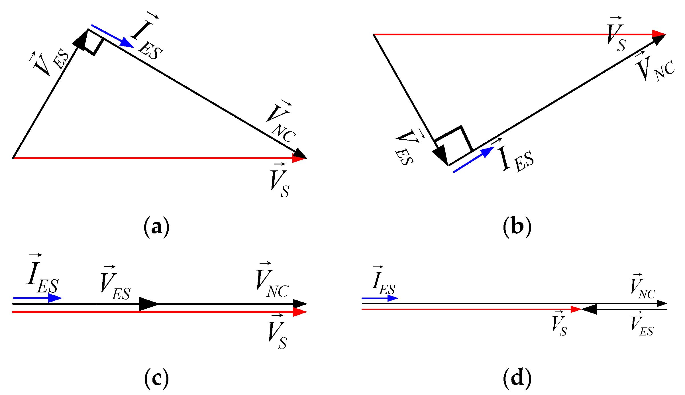
The first topology defined as ES-1 was initiated with the ES concept [12], which is realized by half-bridge and/or full-bridge VSIs, shown in Figure 3a,b, respectively. The only difference is that the types of inverter for ES-1 are different. It should be noticed that only the capacitors are used in the DC side of the inverters, which means ES-1 cannot regulate active power, but only pure reactive power instead. As a result, only three compensation functions can be achieved by ES-1, namely:
(1)
Inductive power compensation;
(2)
Capacitive power compensation;
(3)
Resistive compensation.
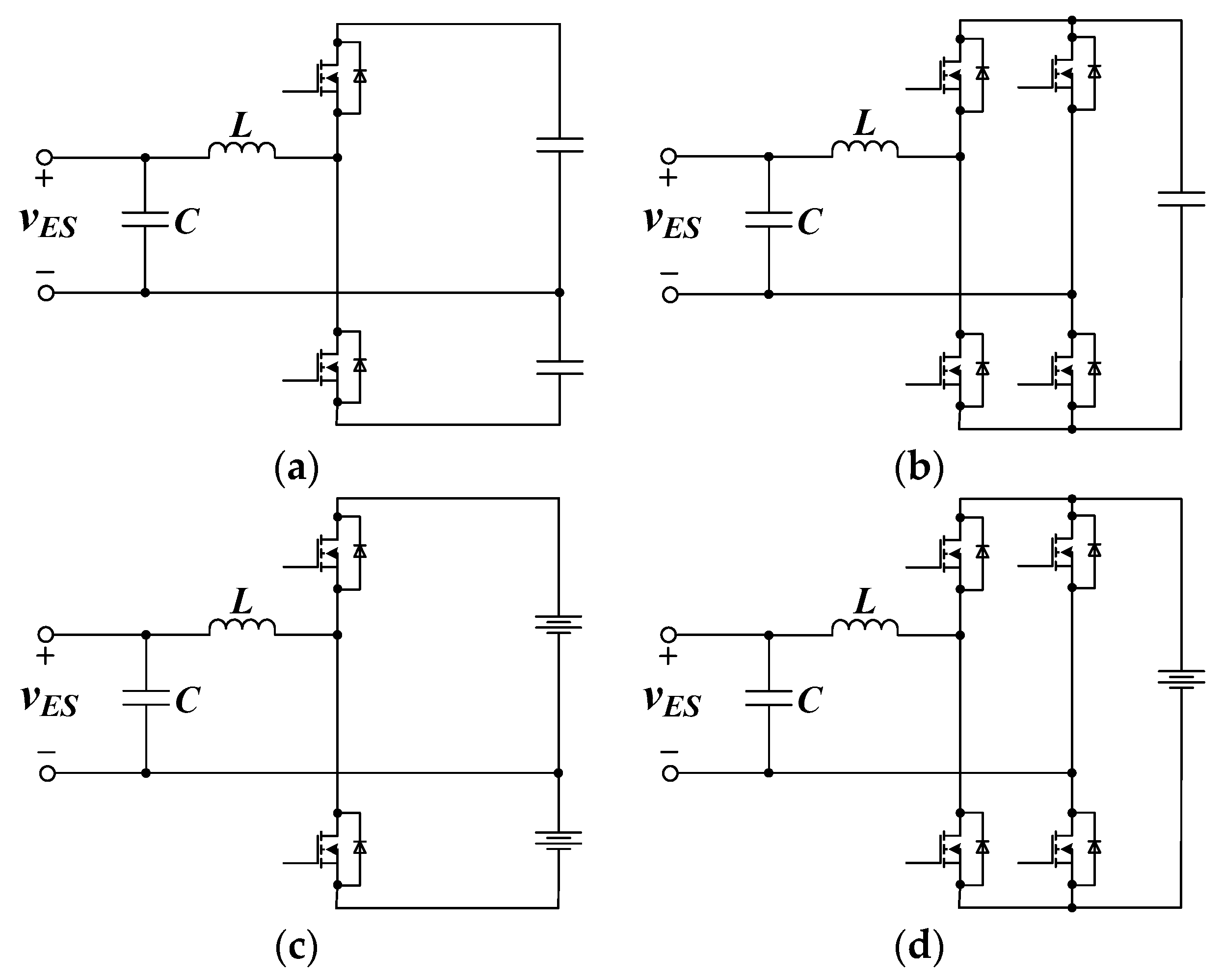
It is easily deduced that ES-1 can only be applied in the applications that only require pure reactive power compensation. By replacing the capacitors with batteries and/or DC voltage sources in ES-1, a different version called ES-2 is obtained. Similar as that of ES-1, different types of ES-2 realized by half-bridge VSI and full-bridge VSI are depicted in Figure 3c,d, respectively. It has been well illustrated in [18] and [30] that eight possible types of voltage and/or power compensation can be supported by ES-2 and namely:
(1)
Inductive power compensation (Figure 4a);
(2)
Capacitive power compensation (Figure 4b);
(3)
Positive real power compensation (Figure 4c);
(4)
Negative real power compensation (Figure 4d);
(5)
Inductive plus positive real power compensation (Figure 5a);
(6)
Inductive plus negative real power compensation (Figure 5b);
(7)
Capacitive plus positive real power compensation (Figure 5c);
(8)
Capacitive plus negative real power compensation (Figure 5d).
In Figure 4 and Figure 5, I E S is the vector of ES current, which equals to the current flowing through the NCL, as shown in Figure 1b. Resistive NCL means that I E S is in phase with V N C .
Different compensation modes of ES-2 are determined by the phase angle between I E S and V E S . For instance, in Figure 4a, I E S lags V E S by 90°, meaning that ES-2 operates at inductive mode. In Figure 5a, the projection of V E S on the axis of I E S is in phase with I E S , while the perpendicular component of V E S leads I E S by 90°, which means that ES-2 operates at inductive plus positive real power compensation mode. The same analogy applies to the other subfigures.

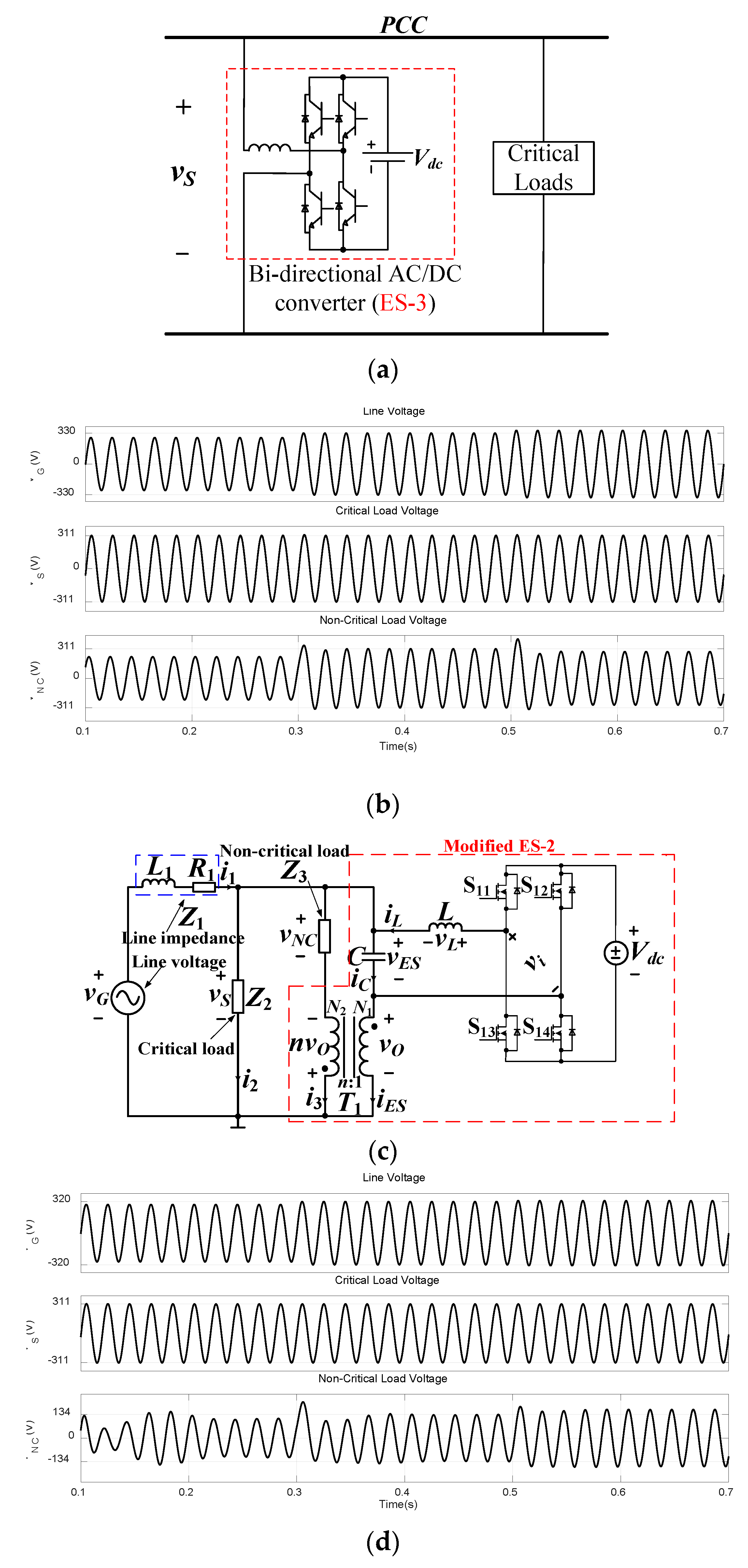
2.3. Existing Topology of ES-3

To stabilize the voltage and frequency of bidirectional grid-connected converters interfacing RESs with the grid, the concept of active suspension was introduced into ES, which is defined as ES-3 without association with any NCL [19], as shown in Figure 6a.
It is obvious that the bidirectional AC/DC converter could also be realized by other topologies. However, from topology point of view, ES-3 seems to be similar with energy storage devices (ESDs) [31,32,33,34]. It should be noticed that ES-3 is also focused on recently.

2.4. Existing Topology of Modified ES-2

Applying KVL to Figure 1b yields:
V E S + V N C = V S
As mentioned above, if the NCL is pure resistive, V N C is perpendicular with V E S when ES-2 operates at pure reactive power compensation mode. At this situation, applying the Pythagorean Theorem to the right-angled triangle, shown in Figure 4a,b, yields:
V S = V E S 2 + V N C 2
It is revealed by (6) that the maximum value of VNC appears only at the moment when VES equals zero. Thus, as VG rises, VNC increases to its maximum value first and then decreases, which is not the same trend as that of VG, as can be seen by comparing the first and third channels of Figure 6b. Aiming at this, a kind of modified version of ES-2 which was named Modified ES-2 was proposed in [20], as shown in Figure 6c. Figure 6d shows the effectiveness of Modified ES-2. From 0.1 to 0.3 s, the amplitude of NCL voltage is less than 134 V, while it equals to 134 V from 0.3 to 0.5 s and exceed 134 V from 0.5 to 0.7 s, which means VNC varies as the same trend as that of VG. It can be seen from the second channels in Figure 6b,d that both CL voltages are well regulated at 220 V as predefined. The disadvantage of Modified ES-2 can also be observed from the third channel in Figure 6d that CL voltage is low. For the NCLs with normal voltage ratings, this is not suitable. However, it is recommended to be used in some low-voltage applications (e.g., water heaters).

2.5. Existing Topology of Isolated ES-2

Most publications aa seen dealt with non-isolated ES topologies. The concept of fully isolated ESs is proposed in [20], where full isolation can be realized by integrating multi-port transformers (MPTs) and ESs. Figure 7a,b show the Isolated ES-2 and its typical application circuit, setting three-port transformer (TPT) and four-port transformer (FPT) as examples.
The proposed Isolated ES-2 offers many advantages over the existing ESs and multi-port converters [35,36]. Compared to non-isolated ES-2, Isolated ES-2 can provide the users with a safer environment because of the isolation among the network participants: microgrid, SLs and CLs. What’s more, it extends the applications of the ESs due to many features, like the possibility for the users to sell high-quality electricity to the power companies and the voltage stabilization of more CLs when the power generation exceeds the local needs [21].
Compared to multi-port converters, Isolated ES-2 has many advantages. For instance, it can reduce the burden of the batteries since they ensure a stable power on CLs by passing the fluctuated power to NCLs. Consequently, Isolated ES-2 helps the application of ES equipment in the distributed power systems. Detailed and extensive functionalities could be found in [21]. It should be noticed that the disadvantage of Isolated ES-2 is also obvious. The power density of the entire system will be reduced due to the additional transformer. As a result, cost and safety should be considered and compromised.

2.6. Existing Topology of CSI-ES

Although a variety of power inverters such as single-phase [37], three-phase [38], two-level and/or multi-level inverters [39,40] are mentioned that can be used to implement an ES [41], few literatures are seen reporting on an ES achieved by CSI [22]. In order to make an easy explanation, such kind of ES is named CSI-ES, as shown in Figure 7c. The differences between CSI-ES and ES-2 can be summarized as follows:
(1)
VSI is replaced by CSI;
(2)
Filter inductor after the inverter is removed.
The equivalent circuit of CSI-ES could be regarded as a current controlled current source (CCCS) and meanwhile the branch with line impedance is replaced by a current source with the value of current equal to that of the branch current. The CSI-ES has to generate an AC current to compensate the fluctuation in input current to achieve a stable CL voltage. From this point of view, the CSI-ES can act as the role as an active power filter (APF) [42]. Besides, it is easily seen that such a current control concept is clear and easy to understand.

2.7. Existing Topology of SLBC

There are many other forms of topologies for single-phase ESs. For example, batteries or voltage sources in ES-2 can be substituted by bi-directional rectifiers [43]; single-phase VSIs could be replaced by multi-level inverters [40] and so on. Figure 7d shows another version of ES topology called SLBC where batteries in the DC side of VSI are replaced by a PWM rectifier. As no energy storage device is required in SLBC, it can support under- and/or over-voltage situations of longer duration depending on the nature of the NCLs.
It also provides more flexibility in terms of control over active and reactive power consumption of the SL, which is called SL with back-to-back converter (SLBC) [44]. When only the grid voltage regulation is needed and there is sufficient input active power for CLs and NCLs, SLBC gives a cost-effective solution that provides reactive power compensation and stores extra power. However, when input active power is too limited to support both loads, SLBC can only provide active power compensation in a limited time. It is risky to use SLBC at such cases when the low-power situation lasts for a long time, especially at the islanding microgrids with high penetration renewables.

2.8. Summary of Single-Phase ES

To understand existing topologies of single-phase ESs easily and clearly, a brief summary is provided to describe the relationships, as shown in Table 1.
(1)
The only difference between ES-1 and ES-2 is that the input components of VSIs are capacitor in ES-1 whilst voltage source or batteries in ES-2;
(2)
ES-3 is the bi-directional AC/DC converter with batteries in the DC side, without NCL at all;
(3)
Modified ES-2 is a kind of modified version of ES-2;
(4)
Isolated ES-2 is the full-isolated version of ES-2;
(5)
In CSI-ES, VSI has been replaced by CSI;
(6)
The difference between SLBC and ES-2 is that voltage source and/or batteries in ES-2 have been replaced by bi-directional PWM rectifier in SLBC.
For the application in which only reactive power regulation is needed, all the topologies discussed above could be the choices; if active power regulation is mandatorily required, ES-1 cannot be used.
If total input active power is not sufficient enough to support both CLs and NCLs, and the duration time is so long and frequent, SLBC cannot be selected; when power generation at domestic homes or buildings mainly relies on small wind turbines or roof PV panels, Isolated-ES-2 is highly recommended if power density is not the key consideration; if a great many NCLs can suffer low voltage and power ratings, Modified ES-2 is a good choice; at the locations where both techniques and devices of superconducting magnetic energy storage (SMES) [45] are mature, CSI-ES could be a cost-effective solution. For applications in future microgrids with high penetration of intermittent RESs which require both compact hardware and high power density, SLBC could be the solution to migrate both voltage and frequency fluctuations [46].

3. Three-Phase ESs

In this section, existing topologies of three-phase ESs (TPESs) are reviewed and discussed. To achieve a better illustration, all of them are sequenced as TPES-1, TPES-2, TPES-3 and TPES-4, etc.

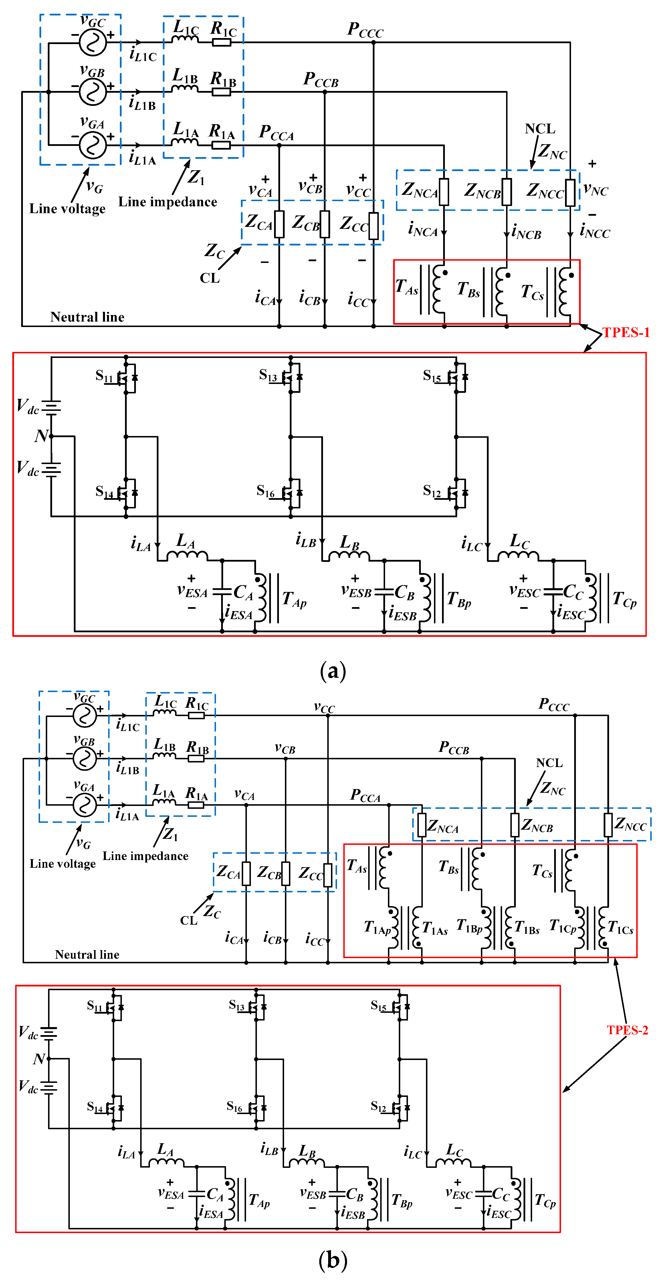
3.1. Existing Topology of TPES-1

The first TPES, which is used to reduce three-phase power imbalance, was seen in [22]. This version is sequenced as TPES-1, as shown in the red solid lines in Figure 8a. In the subfigure, vG is the (fluctuating) microgrid voltage; vGA, vGB and vGC denote three line voltages; Z1 is the line impedance with a resistor and an inductor in each phase; vCA, vCB and vCC are the PCC voltages which are applied to both CL and SL; ZC is the three-phase CL load; iC is the current through ZC; ZNC is the three-phase NCL load; vNC and iNC are the voltage and current of NCL, respectively. TPES-1 consists of two DC voltage sources with a middle point N, a three-phase DC/AC inverter and three separate LC filters with the capacitors paralleled to the primary windings of three different transformers and with the secondary windings placed in series with NCLs; the voltage across each capacitor, denoted as vES, is termed as the ES voltage, whilst the current through L, denoted as iL, is termed as ES current [47].
It is believed that the neutral current could be reduced greatly by applying proper control to TPES-1, meaning that a lot of conduction losses could be avoided in the cables in the buildings’ power systems [23].

3.2. Existing Topology of TPES-2

As mentioned in [23], TPES-1 is an extension of ES-2. Since there are a number of single-phase ES topologies reported in the literature, a normal way of thinking is to extend them to the three-phase system.
In this subsection, the extension of Modified ES-2 is provided, as shown in the red solid lines in Figure 8b. Compared to Figure 8a, the main circuits including three-phase VSIs, LC filters, and the transformers designated as TA, TB, and TC are the same. The only difference is that an additional transformer is added in each phase to ensure the NCL voltages vary as the same trends as that of line voltages. It should be noticed that the blocks on the lower side in both Figure 8a,b are the same while the difference is located in the blocks on the upper side. The functionalities of TPES-2 are similar as that of Modified ES-2 [48].

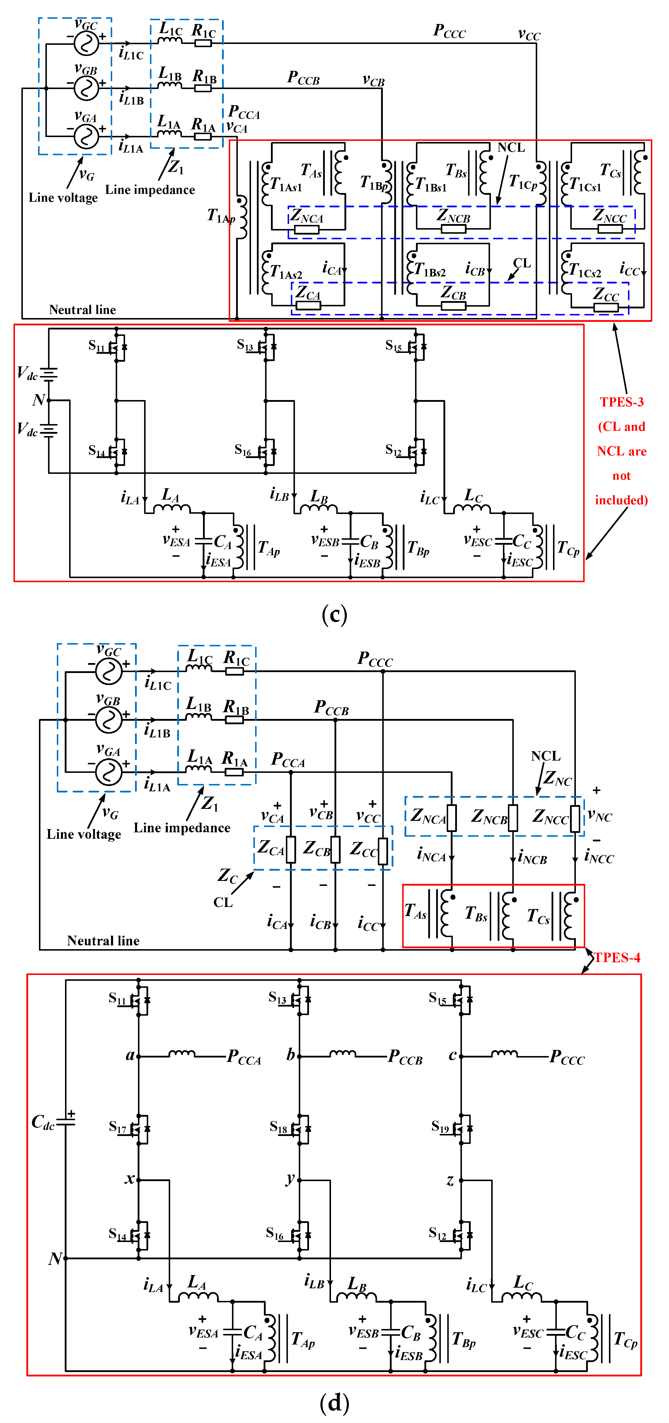
3.3. Existing TPES-3 Topologies

TPES-3 is shown in Figure 8c, where the circuitry in the lower block is also the same as that of Figure 8b. Besides the transformer T, another kind of transformer designated as T1 is added in each phase to achieve full isolation among CLs, NCLs and also AC voltage sources. It should be noted that CLs and NCLs in the dashed lines are not included in TPES-3. The basic functionalities of TPES-3 are similar as that of Isolated ES-2.

3.4. Existing Topology of TPES-4

Besides the extensive solution, other attempts have been tried to achieve different topologies for TPESs. Figure 8d depicts a new version sequenced as TPES-4 which is realized by a nine-switch topology [49]. The lower block in red solid lines is totally different from previous topologies of TPESs. The output terminals of TPES-4 are divided into two sets. The three terminals on the upper side of nine-switch inverter, marked as a, b, and c and defined as the output of shunt VSI, are connected to PCCA, PCCB, and PCCC through a filter inductor in each phase, respectively. The other three terminals on the lower side of nine-switch inverter, designated as x, y, and z, are defined as the output of series VSI. Three additional switches in the middle, designated as S17, S18 and S19, are shared between the shunt and series VSIs. The shunt VSI regulates the DC voltage on the DC-link capacitor whereas the series VSI passes the voltage fluctuations from PCC to NCLs [49]. TPES-4 performs active compensation without the requirement of energy storage for all operational modes. In the positive real compensation mode, the active power required for series VSI is obtained from the grid through the shunt VSI, whereas in the negative real compensation mode, the active power absorbed by the series VSI is injected back to the grid via the shunt VSI. As a result, the active power burden and voltage rating of series VSI switches decreases a lot compared to conventional TPES configuration.
It is obvious that batteries or voltage sources in the DC side of TPES-4 are replaced by a capacitor. Previous work reveals that a PWM rectifier will be used if not using the active components in the DC side of VSI, which means additional six switches should be added for the three-phase PWM rectifier. The big advantage of the nine-switch inverter is that both functionalities of PWM rectifier and inverter have been achieved while three switches are reduced due to the shared three in the middle. However, the disadvantage is also obvious which is similar as that of SLBC. For the situation with long-time and frequent power sag, especially in islanded microgrids with high proportion of power generated from RESs, it is not recommended.

3.5. Summary of Three-Phase ESs

A brief summary has also been provided to describe the relationships among TPESs:
(1)
TPES-1 is the basic topology, an extension of ES-2;
(2)
TPES-2 is an extension of Modified ES-2;
(3)
TPES-3 is an extension of Isolated ES-2;
(4)
TPES-4 is a simplified version, which achieves the same function if using a three-phase PWM rectifier to replace the batteries in TPES-1.
For the applications where active and reactive power regulations are needed, all the versions of TPESs could be the solutions; if total input active power is not sufficient enough to support both CLs and NCLs and meanwhile the duration time is so long and frequent, TPES-4 cannot be selected; if a great many of NCLs can suffer low voltage and power ratings, TPES-2 is a better choice; when power generation mainly rely on small wind turbines or roof PV panels, TPES-3 is highly recommended if power density is not the key consideration; TPES-4 is suitable for such applications that require cost-effective and also compact size in hardware. In summary, the characteristics and possible applications of TPESs are listed in Table 2.

4. DCESs

Taking the advantages of DC microgrids into account, their applications such as high-efficiency households, renewable energy parks, data centers, vehicular electric power systems, hybird energy storage systems, electric vehicle (EV) charging stations using DC chargers, etc. have developed rapidly [13]. Since so many DC loads are connected, it is necessary to ensure the DC microgrids operate in a stable way and provide high power quality at PCC. Fortunately, the concept of ES has been extended to DC systems [28]. In this section, a critical review on existing topologies is presented. Similarly, they are sequenced as DCES-1 and DCES-2 etc.

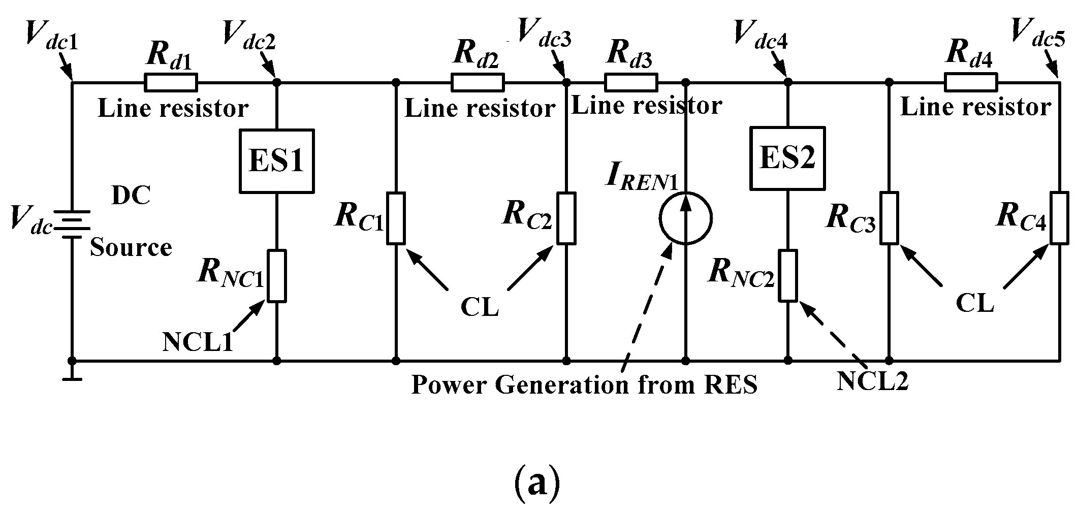
4.1. Existing Topology of DCES-1

The initial concept of DCES [28] is shown in Figure 9a, which is sequenced as DCES-1 in this paper. It should be noticed that the implementation circuit is the same as that of ACES.
In Figure 9a, Vdc denotes the DC voltage source; Rd is the resistance of distribution line; RC and RNC represent CL and NCL, respectively; ES1 and ES2 are DCESs; IREN1 denotes the injected current from RESs. Figure 9b shows the typical application of a DCES-1.
It has been validated that the proposed DCES can regulate the voltage level of busbar of DC power systems [28]. However, there are some disadvantages by using ACES to operate at DC-ES mode. For instance, since the topology itself remains the same as existing ES-2, volume of the filter is so big that it decreases the system power density. As a result, it’s better to use other topologies to avoid the filter above.

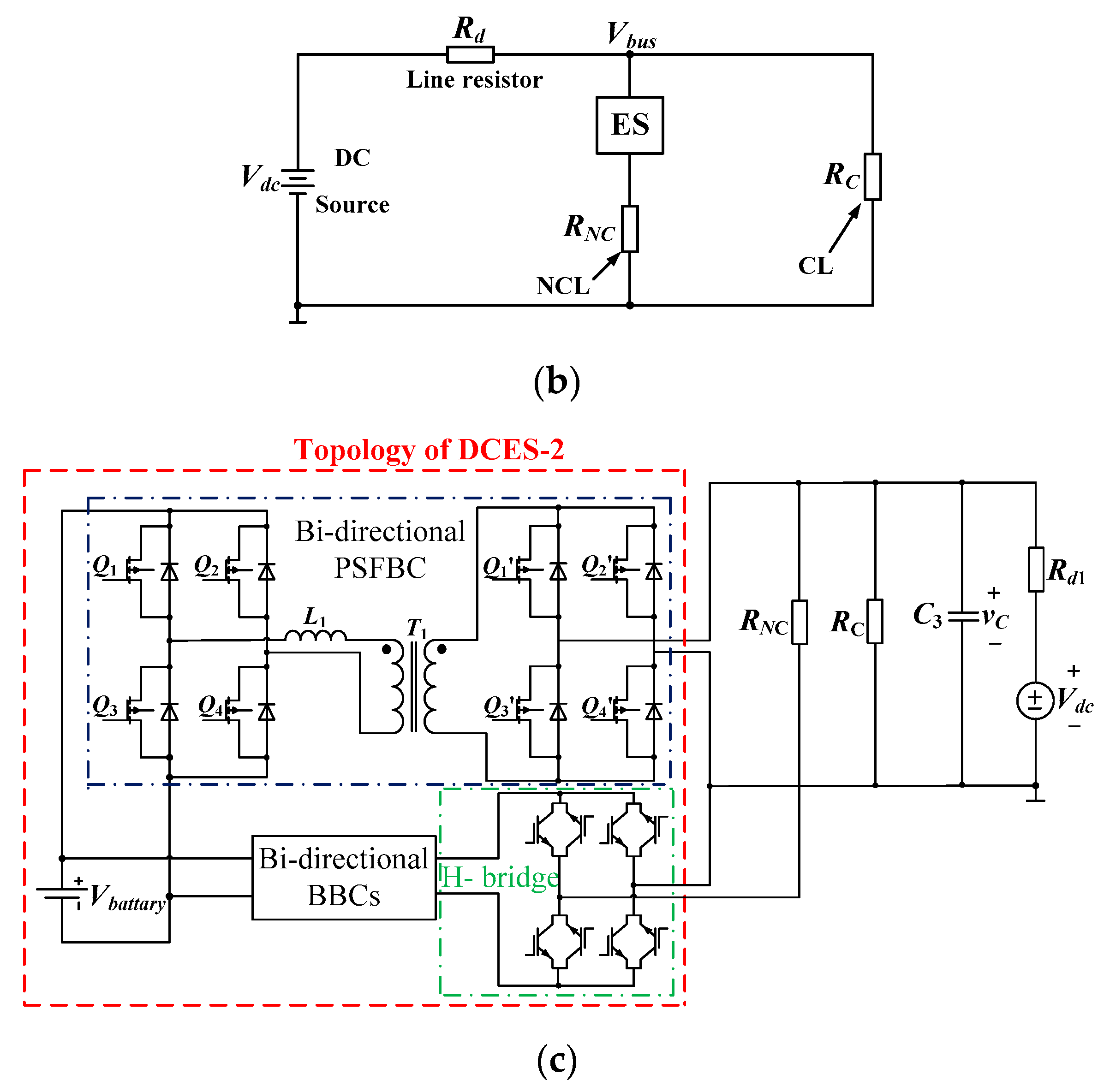
4.2. Existing Topology of DCES-2

Aiming at improving system efficiency and power density, a new type of DCES realized by DC/DC converters is proposed in [29], which is sequenced as DCES-2 and shown in Figure 9c. It consists of three parts, namely bi-directional buck-boost converters (BBCs), bi-directional phase-shift full-bridge converter (PSFBC), and H-bridge circuit. The key functionality of this kind of DCES is still to regulate DC bus voltage to the required level while passing part of the input fluctuations to NCLs and the other to storage devices such as batteries.
Three basic operating modes, such as voltage boosting mode, voltage balancing mode and voltage suppression mode can be achieved. Besides the normal function, to secure the normal operation of the proposed DCES, a protection mechanism is designed to charge and/or discharge batteries rapidly with a constant current at abnormal states.

4.3. Other Configurations of DCES

In order to reduce the total energy storage capacity in the PV systems, a new configuration of DCES defined as PVES is proposed in [50], where a part of PV batteries act as energy storage device for DCES. It is obviously seen that PVES can tackle the intermittency of the solar power with a smaller storage capacity.

4.4. Summary of DCESs

The advantage of DCES-2 over DCES-1 can be summarized as follows.
(1)
Volume and cost of filter is much lower;
(2)
Power density is higher;
(3)
DC/DC converters instead of DC/AC inverters.
However, the control of DCES-2 seems complicated due to its structure and functionality. As a result, further work should be done on the topology improvement.
Both DCES-1 and DCES-2 can be used in DC microgrids with penetration of RESs. Considering PVES can regulate the PCC voltage with less storage capacity, it is promising and suitable for the roof PV systems.

5. Comparison between ES and Other FACTS Devices

In this part, a general comparison has been done between traditional FACTS devices and ES-2. Different connections and characteristics are thoroughly analyzed.

5.1. Comparison with SSSC

SSSC is a series FACTS device [18], as shown in Figure 10a. It is observed that the NCL has equal status as the CL in SSSC while they are different in the ES shown in Figure 10b. Besides topology differences, SSSCs are normally located at critical nodes of grid with centralized control, while ESs are distributed at the end users with decentralized control. One single failure of ES does not have an obvious influence on the operation of the grid.

5.2. Comparison with STATCOM

A typical STATCOM connection applied in power systems [51] is shown as Figure 10c. STATCOM is also a kind of FACTS devices which has large volume, requires centralized control and relies on communication technology. Besides, it mainly provides reactive power compensation. From this point of view, it is similar to SSSC. However, it is paralleled device, which is different from SSSC. As a result, the advantages that ESs over SSSC are also effective on STATCOM. It is validated in [51] that a group of ESs require less reactive power capacity than a single STATCOM based on the same ability of voltage regulation.

5.3. Comparison with UPFC

A typical configuration of UPFC applied in power systems [52] is shown in Figure 10d. UPFC can be regarded as the series and paralleled FACTS device, which is realized by a back-to-back converter. The position of both CL and NCL are the same as that of SSSC and STATCOM, which is also different with that of the ES.

5.4. Comparison with APF

The difference between an ES and an APF can be described as follows: when harmonic components appear in the ac source, a typical APF detects the harmonic components and then tries to make the total input current clean. An ES can also take such action to compensate for harmonic current to ensure a clean current through the CL while passing the harmonic components to the NCL. From this point of view, the ES and APF are similar. However, an ES has unique functions that an APF does not have. For instance, when fluctuation occurs in the ac source, the ES can pass it to the NCL while ensuring a stable voltage on the CL dynamically. On the contrary, an APF only deals with harmonic compensation and does not focus on the regulation of PCC voltage and unpredictable power.

5.5. Summary

FACTS devices, such as SSSC, STATCOM and UPFC are located at critical nodes of grid. Almost all of them have big volume and require centralized control which relies on communication technology. ESs can be located at distributed networks which can avoid communications. What’s more, failures of FACTS devices may result in abnormal operations of power systems. In contrast, failure of a single ES almost has little influence on the system operation. The detailed comparisons can be seen in Table 3.
From a topology point of view, the ES might also be regarded as one kind of series device. The difference is that it has smaller power rating and the SL formed by the ES and the NCL can be regarded as a parallel device to the CL.

6. Conclusions

This paper has provided a comprehensive overview of the state of the art in topologies of ESs. Different from an existing review [53], only topologies are focused on. Several types of prominent topologies are introduced before discussing their suitability for practical applications, especially at domestic households:
(1)
For the single-phase ESs, four additional topologies are analyzed besides the initial three versions, pointing out that each topology has its own advantages and disadvantages.
(2)
For the TPESs, the initial topology sequenced as TPES-1, is described firstly. Then, another two kinds of topologies such as TPES-2 and TPES-3 are analyzed, which are extended from modified ES-2 and Isolated ES-2, respectively. A new version realized by a nine-switch topology is described which is sequenced as TPES-4.
(3)
For the DCESs, three kinds of topologies are discussed, of which the one sequenced as DCES-1 has the same structure as ES-2, the one sequenced as DCES-2 is realized by complicated DC/DC converters, and the third one called PVES is a new configuration sharing a part of PV batteries with DCES topologies. The prominent advantage of DCES-2 over DCES-1 is its higher power density.
So far, there are no mature products in the market. This paper is not only motivated by the recent outburst of literatures on the ESs, but also by an immense number of practical and residential applications. Given the increasing penetration of RESs in modern distributed power systems, it is foreseeable that the ESs will be continuously popular in the next few years. Considering the ES topologies are the main focused in this paper, several research trends can be pointed out as follows:
(1)
Great interest will be seen in the topology improvement of single-phase ESs. One of the trends is that ES-2 in fact is a series compensator, which is not consistent with traditional connection way of electric loads in power systems, especially for NCLs. For this matter, a new topology of single-phase ES could be one of the directions that not only can realize existing functionalities, but also can improve existing connecting configuration.
(2)
Another trend is that although Modified ES-2s achieve some progress compared to ES-2s, the side effect that the nominal voltage class of the NCL becomes lower occurs. As a result, how to improve the Modified ES-2 could be the possible study direction.
(3)
The third trend is that current ES-3 has no NCL in the topology which offers a chance for further improvement.
(4)
The fourth direction is to improve the power density of Isolated ES-2 while keeping full isolation among CLs, SLs and input voltage sources.
(5)
The final trend but also the most important trend for single-phase ES is to find a possible solution for SLBC to make it suitable for the islanded operation with long-time and frequent power sag. Meanwhile, the power management strategy inside the ESs should be considered.
(6)
Other trends include topology improvement in TPESs and DCESs.
It should be noticed that the state of the art of overview of control and applications of the ESs will be covered in other literatures due to the length limitations.

Author Contributions

Q.W. conceived the idea of this paper and performed the simulations and also experiments, wrote the paper. F.D., M.C. and G.B. provided guidance and revised the manuscript and added their thinking to validate the idea. All authors have equally contributed to the analysis and discussions.

Funding

This work was supported by the Natural Science Foundation of Jiangsu Province under project BK20170675, and by the National Natural Science Foundation of China under project 51320105002, and by the National Natural Science Foundation of China under project 51667014,and by the Fundamental Research Funds for the Central Universities under project 2242018K40075.

Conflicts of Interest

The authors declare no conflict of interest.

References

  1. Cheng, M.; Zhu, Y. The state of the art of wind energy conversion systems and technologies: A review. Energy Convers. Manag. 2014, 88, 332–347. [Google Scholar] [CrossRef]
  2. Deng, F.; Zhu, R.; Liu, D.; Wang, Y.; Wang, H.; Chen, Z.; Cheng, M. Protection scheme for modular multilevel converters under diode open-circuit faults. IEEE Trans. Power Electron. 2018, 33, 2866–2877. [Google Scholar] [CrossRef]
  3. Sotoodeh, P.; Miller, R.D. Design and implementation of an 11-level inverter with FACTS capability for distributed energy systems. IEEE J. Emerg. Sel. Top. Power Electron. 2014, 2, 87–96. [Google Scholar] [CrossRef]
  4. Dionise, T.J. Assessing the performance of a static var compensator for an electric arc furnace. IEEE Trans. Ind. Appl. 2014, 50, 1619–1629. [Google Scholar] [CrossRef]
  5. Du, S.; Liu, J.; Lin, J.; He, Y. A novel DC voltage control method for STATCOM based on hybrid multilevel H-Bridge converter. IEEE Trans. Power Electron. 2013, 28, 101–111. [Google Scholar] [CrossRef]
  6. Rai, D.; Faried, S.O.; Ramakrishna, G.; Edris, A.A. An SSSC-based hybrid series compensation scheme capable of damping subsynchronous resonance. IEEE Trans. Power Deliv. 2012, 27, 531–540. [Google Scholar] [CrossRef]
  7. Ebrahimzadeh, E.; Farhangi, S.; Iman-Eini, H.; Ajaei, F.B.; Iravani, R. Improved phasor estimation method for dynamic voltage restorer applications. IEEE Trans. Power Deliv. 2015, 30, 1467–1477. [Google Scholar] [CrossRef]
  8. Peng, F.; Liu, Y.; Yang, S.; Zhang, S.; Gunasekaran, D.; Karki, U. Transformer-less unified power-flow controller using the cascade multilevel inverter. IEEE Trans. Power Electron. 2016, 31, 5461–5472. [Google Scholar] [CrossRef]
  9. Dragicevic, T.; Lu, X.; Vasquez, J.C.; Guerrero, J.M. DC-microgrids—Part II: A review of power architectures applications and standardization issues. IEEE Trans. Smart Grid 2016, 31, 3528–3549. [Google Scholar] [CrossRef]
  10. Ding, Z.; Yang, C.; Zhang, Z.; Wang, C.; Xie, S. A novel soft-switching multiport bidirectional DC-DC converter for hybrid energy storage system. IEEE Trans. Power Electron. 2014, 29, 1595–1609. [Google Scholar] [CrossRef]
  11. Hredzak, B.; Agelidis, V.G.; Jang, M. A model predictive control system for a hybrid battery-ultra capacitor power source. IEEE Trans. Power Electron. 2014, 29, 1469–1479. [Google Scholar] [CrossRef]
  12. Hui, S.Y.R.; Lee, C.K.; Wu, F. Electric springs—A new smart grid technology. IEEE Trans. Smart Grid 2012, 3, 1552–1561. [Google Scholar] [CrossRef]
  13. Guerrero, J.M.; Vasquez, J.C.; Matas, J.; Matas, J.; de Vicuna, L.G.; Castilla, M. Hierarchical control of droop-controlled AC and DC microgrids—A general approach toward standardization. IEEE Trans. Ind. Electron. 2011, 58, 158–172. [Google Scholar] [CrossRef]
  14. Xie, C.; Zhao, X.; Li, K.; Zou, J.; Josep, M.G. A new tuning method of multi-resonant current controllers for grid-connected voltage source converters. IEEE J. Emerg. Sel. Top. Power Electron. 2018. [Google Scholar] [CrossRef]
  15. Sheikhi, A.; Rayati, M.; Bahrami, S.; Mohammad, A. Integrated demand side management game in smart energy hubs. IEEE Trans. Smart Grid 2015, 6, 675–683. [Google Scholar] [CrossRef]
  16. Lee, C.K.; Hui, S.Y.R. Reduction of energy storage requirements in future smart grid using electric springs. IEEE Trans. Smart Grid 2013, 4, 1282–1288. [Google Scholar] [CrossRef]
  17. Lee, C.K.; Cheng, K.L.; Ng, W.M. Load characterisation of electric spring. In Proceedings of the IEEE Energy Conversion Congress and Exposition (ECCE), Denver, CO, USA, 15–19 September 2013; pp. 4665–4670. [Google Scholar]
  18. Tan, S.C.; Lee, C.K.; Hui, S.Y.R. General steady-state analysis and control principle of electric springs with active and reactive power compensations. IEEE Trans. Power Electron. 2013, 28, 3958–3969. [Google Scholar] [CrossRef]
  19. Lee, C.K.; Hui, S.Y.R. Input AC voltage control bi-directional power converters. U.S. Patent 13,907,350, 31 May 2013. [Google Scholar]
  20. Wang, Q.; Cheng, M.; Chen, Z.; Buja, G. A novel topology and its control of single-phase electric springs. In Proceedings of the International Conference on Renewable Energy Research and Applications, Palermo, Italy, 22–25 November 2015; pp. 267–272. [Google Scholar]
  21. Wang, Q.; Cheng, M.; Buja, G. Integration of electric springs and multi-port transformers—A new solution for AC microgrids with renewable energy sources. Energies 2017, 10, 193. [Google Scholar] [CrossRef]
  22. Wang, Q.; Cheng, M.; Jiang, Y. Harmonics suppression for critical loads using electric springs with current-source inverters. IEEE J. Emerg. Sel. Top. Power Electron. 2016, 4, 1362–1369. [Google Scholar] [CrossRef]
  23. Yan, S.; Tan, S.C.; Lee, C.K.; Hui, S.Y.R. Reducing three-phase power imbalance with electric springs. In Proceedings of the IEEE International Symposium on Power Electronics for Distributed Generation Systems (PEDG), Galway, Ireland, 24–27 June 2014; pp. 1–7. [Google Scholar]
  24. Yan, S.; Tan, S.C.; Lee, C.K.; Chaudhuri, B.; Hui, S.Y.R. Electric springs for reducing power imbalance in three-phase power systems. IEEE Trans. Power Electron. 2015, 30, 3601–3609. [Google Scholar] [CrossRef]
  25. Wang, P.; Xiao, J.; Setyawan, L. Hierarchical control of hybrid energy storage system in DC microgrids. IEEE Trans. Ind. Electron. 2015, 62, 4915–4924. [Google Scholar]
  26. Diaz, N.L.; Dragicevic, T.; Vasquez, J.C.; Guerrero, J.M. Intelligent distributed generation and storage units for DC microgrids—A new concept on cooperative control without communications beyond droop control. IEEE Trans. Smart Grid 2014, 5, 2476–2485. [Google Scholar] [CrossRef]
  27. Rani, B.I.; Bango, G.S.; Nagamani, C. Control strategy for power flow management in a PV system supplying DC loads. IEEE Trans. Ind. Electron. 2013, 60, 3185–3194. [Google Scholar] [CrossRef]
  28. Mok, K.T.; Wang, M.H.; Tan, S.C.; Hui, S.Y.R. DC electric springs—An emerging technology for DC grids. In Proceedings of the IEEE Applied Power Electronics Conference and Exposition (APEC), Charlotte, NC, USA, 15–19 March 2015; pp. 684–690. [Google Scholar]
  29. Wang, Q.; Cheng, M.; Chen, Z.; Deng, F.; Wang, Z. DC electric springs with DC/DC converters. In Proceedings of the IEEE International Power Electronics and Motion Control Conference (IPEMC-ECCE Asia), Hefei, China, 22–25 May 2016; pp. 3268–3273. [Google Scholar]
  30. Wang, Q.; Cheng, M.; Chen, Z.; Wang, Z. Steady-state analysis of electric springs with a novel δ control. IEEE Trans. Power Electron. 2015, 30, 7159–7169. [Google Scholar] [CrossRef]
  31. Yang, T.; Mok, K.T.; Tan, S.C.; Hui, S.Y.R. Control of electric springs with coordinated battery management. In Proceedings of the IEEE Energy Conversion Congress and Exposition (ECCE), Montreal, QC, Canada, 20–24 September 2015; pp. 4740–6746. [Google Scholar]
  32. Pozzebon, G.G.; Machado, R.Q.; Buso, S.; Spiazzi, G. A grid-connected multilevel converter for interfacing PV arrays and energy storage devices. In Proceedings of the IEEE Industrial Electronics Society Annual Conference, Vienna, Austria, 10–13 November 2013; pp. 6158–6163. [Google Scholar]
  33. Li, K.; Xu, H.; Ma, Q.; Zhao, J. Hierarchy control of power quality for wind-battery energy storage system. IET Power Electron. 2014, 7, 2123–2132. [Google Scholar] [CrossRef]
  34. Wang, W.; Duan, J.; Wu, F.; Sun, L.; Wang, S. DC-bus hybird energy storage devices cooperation control strategy for stand-along inverter under imbalance load. In Proceedings of the International Conference on Electrical Machines and Systems (ICEMS), Hangzhou, China, 22–25 October 2014; pp. 295–301. [Google Scholar]
  35. Chien, L.J.; Chen, C.C.; Chen, J.F.; Hsieh, Y.P. Novel three-port converter with high-voltage gain. IEEE Trans. Power Electron. 2014, 29, 4693–4703. [Google Scholar] [CrossRef]
  36. Strunz, K.; Abbasi, E.; Huu, D.N. DC microgrid for wind and solar power integration. IEEE J. Emerg. Sel. Top. Power Electron. 2014, 2, 115–126. [Google Scholar] [CrossRef]
  37. Serban, I. Power decoupling method for single-phase H-bridge inverters with no additional power electronics. IEEE Trans. Ind. Electron. 2015, 62, 4805–4813. [Google Scholar] [CrossRef]
  38. Judewicz, M.G.; Gonzalez, S.A.; Echeverria, N.I.; Fischer, J.R.; Carria, D.O. Generalized predictive current control (GPCC) for grid-tie three-phase inverters. IEEE Trans. Ind. Electron. 2016, 63, 4475–4484. [Google Scholar] [CrossRef]
  39. Gong, Z.; Wu, X.; Dai, P.; Zhu, R. Modulated model predictive control for MMC-based active front-end rectifiers under unbalanced grid conditions. IEEE Trans. Ind. Electron. 2018. [CrossRef]
  40. Li, K.; Li, M.; Liang, Z.; Dong, Z.; Tian, S. Analytical closed-form expressions of DC current ripple for three-level neutral point clamped inverters with space-vector pulse-width modulation. IET Power Electron. 2016, 9, 930–937. [Google Scholar]
  41. Lee, C.K.; Chaudhuri, B.; Hui, S.Y.R. Hardware and control implementation of electric springs for stabilizing future smart grid with intermittent renewable energy sources. IEEE J. Emerg. Sel. Top. Power Electron. 2013, 1, 18–27. [Google Scholar] [CrossRef]
  42. Zou, Z.; Zhou, K.; Wang, Z.; Cheng, M. Frequency-adaptive fractional-order repetitive control of shunt active power filters. IEEE Trans. Ind. Electron. 2015, 62, 1659–1668. [Google Scholar] [CrossRef]
  43. Zhu, W.; Zhou, K.; Cheng, M.; Peng, F. A high-frequency-link single-phase PWM rectifier. IEEE Trans. Ind. Electron. 2015, 62, 289–298. [Google Scholar] [CrossRef]
  44. Akhtar, Z.; Chaudhuri, B.; Hui, S.Y.R. Smart loads for voltage control in distribution networks. IEEE Trans. Smart Grid 2017, 8, 937–946. [Google Scholar]
  45. Jin, J.; Chen, X. Cooperative operation of superconducting fault-current-limiting cable and SMES system for grounding fault protection in a LVDC network. IEEE Trans. Ind. Appl. 2015, 51, 5410–5414. [Google Scholar] [CrossRef]
  46. Liu, H.; Lee, C.K.; Hui, S.Y.R.; Waffenschmidt, E. Capability analysis and design considerations of electric springs. In Proceedings of the IEEE International Symposium on Power Electronics for Distributed Generation Systems (PEDG), Vancouver, BC, Canada, 27–30 June 2016; pp. 1–6. [Google Scholar]
  47. Wang, Q.; Cheng, M.; Jiang, Y.; Deng, F.; Chen, Z.; Buja, G. Control of three-phase electric springs used in microgrids under ideal and non-Ideal conditions. In Proceedings of the IEEE Industrial Electronics Society Annual Conference (IECON), Florence, Italy, 24–27 October 2016; pp. 2247–2252. [Google Scholar]
  48. Wang, Q.; Cheng, M.; Jiang, Y.; Deng, F.; Buja, G.; Wang, Y.; Chen, Z. Novel topology of three-phase electric spring and its control. In Proceedings of the IEEE Industrial Electronics Society Annual Conference (IECON), Beijing, China, 29 October–1 November 2017; pp. 2600–2605. [Google Scholar]
  49. Rauf, A.M.; Khadkikar, V.; Elmoursi, M.S. An integrated system configuration for electric springs to enhance the stability in future smart grid. In Proceedings of the Modern Electric Power Systems (MEPS), Wroclaw, Poland, 6–9 July 2015; pp. 1–5. [Google Scholar]
  50. Wang, M.; Tan, S.C.; Lee, C.K.; Hui, S.Y.R. A configuration of storage system for DC microgrids. IEEE Trans. Power Electron. 2018, 33, 3722–3733. [Google Scholar] [CrossRef]
  51. Luo, X.; Akhtar, Z.; Lee, C.K.; Chaudhuri, B.; Tan, S.C.; Hui, S.Y.R. Distributed voltage control with electric springs: Comparison with STATCOM. IEEE Trans. Smart Grid 2015, 6, 209–219. [Google Scholar] [CrossRef]
  52. Bangash, K.N.; Farrag, M.E.A.; Osman, A.H. Smart control of on load tap changer deployed in low voltage distribution network. In Proceedings of the International Conference on Electric Power and Energy Conversion Systems (EPECS), Sharjah, UAE, 24–26 November 2015; pp. 1–6. [Google Scholar]
  53. Subramani, C.; Ramanand, K.R. A brief review on electric spring: Analysis, control and applications. J. Circuits Syst. Comput. 2017, 27, 183002. [Google Scholar] [CrossRef]
Figure 1. Distribution diagram of single-phase ESs in the power systems. (a) Simplified distribution diagram; (b) Typical application circuit of an ES.
Energies 11 01724 g001
Figure 2. Duality principle from a mechanical spring to an electric spring. (a) Mechanical spring; (b) Duality principle; (c) Operating modes of electric spring.
Energies 11 01724 g002
Figure 3. Typical topologies of ES-1 and ES-2. (a) ES-1 realized by half-bridge VSI; (b) ES-1 realized by full-bridge VSI; (c) ES-2 realized by half-bridge VSI; (d) ES-2 realized by full-bridge VSI.
Energies 11 01724 g003
Figure 4. Vector diagrams under main types of compensation modes with pure resistive NCL. (a) Inductive; (b) Capacitive; (c) Positive real; (d) Negative real.
Energies 11 01724 g004
Figure 5. Vector diagrams under other types of compensation modes with pure resistive NCL. (a) Inductive plus positive real; (b) Inductive plus negative real; (c) Capacitive plus positive real; (d) Capacitive plus negative real.
Energies 11 01724 g005
Figure 6. ES-3 and comparisons between ES-2 and Modified ES-2. (a) ES-3 and its application circuit; (b) Waveforms of ES-2; (c) Circuital scheme of Modified ES-2; (d) Waveforms of Modified ES-2.
Energies 11 01724 g006
Figure 7. Other ES topologies and their typical application circuits. (a) Isolated ES-2 with three-port transformer (TPT); (b) Isolated ES-2 with four-port transformer (FPT); (c) CSI-ES and its typical application circuit; (d) SLBC and its typical application circuit.
Energies 11 01724 g007
Figure 8. Topologies and typical application circuits of TPES-1, TPES-2, TPES-3 and TPES-4. (a) TPES-1; (b) TPES-2; (c) TPES-3; (d) TPES-4.
Energies 11 01724 g008aEnergies 11 01724 g008b
Figure 9. Typical topologies and applications of DCES in DC microgrids. (a) Typical application circuit of multiple DCESs [28]; (b) Typical application circuit of a single DCES [28]; (c) DCES-2 realized by DC/DC converters [29].
Energies 11 01724 g009aEnergies 11 01724 g009b
Figure 10. Typical configuration of ES and FACTS devices applied in power systems. (a) SSSC; (b) ES-2; (c) STATCOM; (d) UPFC.
Energies 11 01724 g010
Table 1. Relationships and Comparisons between Different Single-Phase ESs.
ES VersionsCharacteristicsAdvantagesDisadvantagesPossible Applications
ES-1Capacitor in the DC side of VSIThe simplest versionCannot regulate active power, NCL is in series with ESApplications requiring only pure reactive power compensation
ES-2DC voltage source or batteries in the DC side of VSICan regulate both active power and reactive powerNCL is in series with ESAll the possible applications
ES-3No NCLNot series connectionNo NCL, different with the initial ES conceptAll the possible applications
Modified ES-2Modified version of ES-2 with an additional transformer addedCan achieve different operating functionsPower density is lower than normal ES-2, cost upApplications with NCLs that have low voltage and power ratings
Isolated-ES-2Fully-isolated version of ES-2 with a multi-port transformerInput voltage source, CL and SL are electrically isolated; Can achieve more functions than ES-2Power density is lower than normal ES-2, cost upAll the possible applications, except that requires high power density
CSI-ESThe first version realized by CSIDirect current control can be used; Easier to understand ESNeed to generate DC current source firstApplications with CSI input and mature SMES technique and devices
SLBCDC voltage source being replaced by PWM rectifierNo DC voltage source or batteriesMight meet with power sagAll the possible applications, except the case with insufficient input power
To be continued///
Table 2. Characteristics and possible applications of three-phase ESs.
ES VersionsCharacteristicsPossible Applications
TPES-1Basic topology, the extension of ES-2All the possible applications compensation
TPES-2The extension of Modified ES-2Applications where NCSs have low voltage and power ratings
TPES-3The extension of Isolated ES-2Applications where power density is not the key consideration
TPES-4The simplified versionApplications that require cost-effective and compact size in hardware
Table 3. Brief comparisons between FACTS devices and single-phase ES-2.
ES VersionsConnection TypeControl MethodOther Characteristics
ES-2SeriesInput voltage control [12] for CL, output control for NCL; Distributed controlTransformer optional
SSSCSeriesOutput control; Centralized controlTransformer needed
STATCOMParallelOutput control; Centralized controlTransformer needed
UPFCSeries and parallelOutput control; Centralized controlTransformer needed
APFMainly parallelOutput control; Centralized controlTransformer needed

