1. Introduction
At present, in the face of the global energy crisis and environmental pollution problems, hybrid electric vehicles (HEVs), as an environmentally friendly choice, have been developed rapidly. The HEVs use a dual-rotor motor as a power distribution device, together with an advanced control system, to make the two power units, i.e., the internal combustion engine (ICE) and battery cooperate to achieve low energy consumption and low pollution [
1]. Nowadays, power distribution devices mainly contain electric variable transmission (EVT), a compound-structure permanent-magnet motor (CSPM motor), a switched reluctance motor (SRM), magnetic-geared EVT, and the radial magnetic-field modulated brushless double-rotor machine (RMFM-BDRM), whose performances directly affect the quality of HEVs [
2,
3,
4,
5,
6].
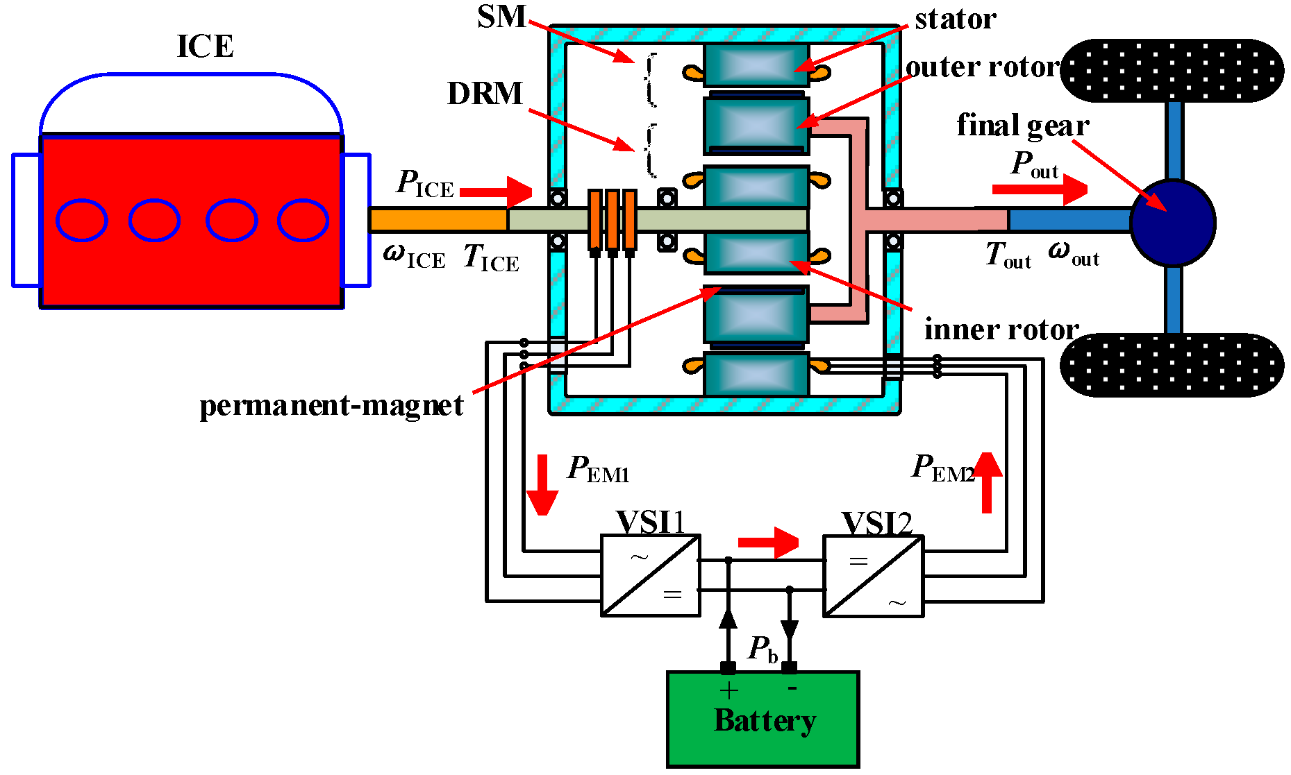
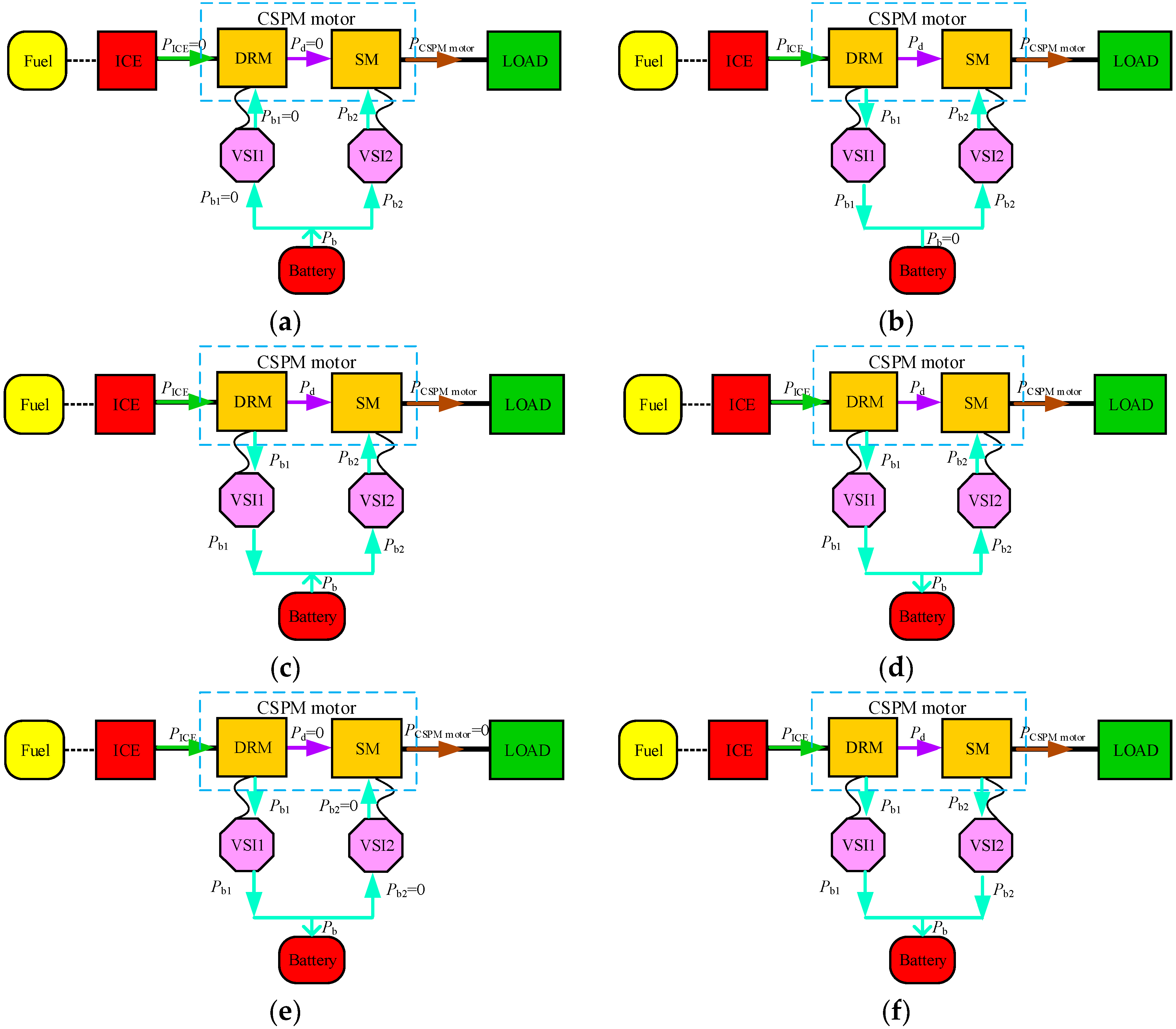
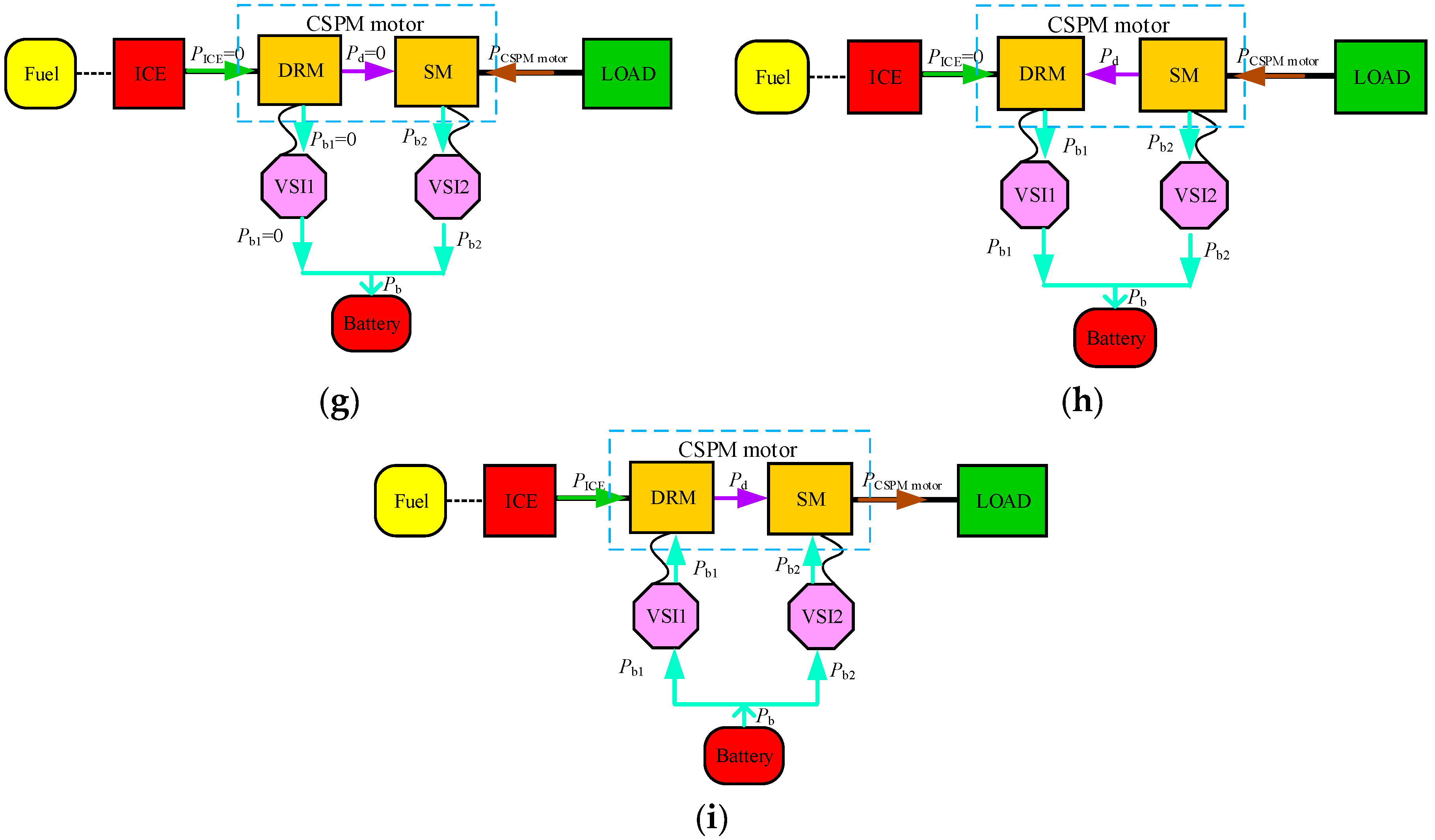
The CSPM motor as an electromechanical energy conversion device with a dual-rotor structure has been widely utilized in industry, for instance in HEVs, due to the high torque density, wide speed range, and long working life. The CSPM motor can achieve different energy flows in HEVs and transmit torque to drive the vehicle. However, it also has the problem of electromagnetic coupling, which affects the driving force and running stability. To achieve electromagnetic decoupling in the CSPM motor, the following research has been carried out by national and international scholars and researchers [
7,
8,
9,
10,
11,
12]: (1) studying the working principle of the CSPM motor under compound excitation source using the magnetic circuit mathematical model and analyzing its inductance parameters based on the finite element method (FEM); (2) studying the influence of structural parameters on the coupling degree to optimize the electromagnetic structure of the CSPM motor. Different electromagnetic structure schemes are designed and compared, such as the different permanent magnet sizes, outer rotor yoke thicknesses, stator winding armature reaction, and material utilization ratios; (3) studying the different topology schemes of the CSPM motor, then the electromagnetic coupling degree, torque density and heat dissipation are compared to meet the different requirements in the hybrid power system; (4) establishing the magnetic network calculation model, together with the Matlab software to analyze the parameters of CSPM motor. The influence of structural parameters on the electromagnetic coupling degree is explored in order to optimize the structural parameters; (5) studying the torque control strategy of the CSPM motor based on the mathematical model and load characteristics, to realize independent control of the output speed and torque.
To meet the demands of the large traction and smooth operation of HEVs, the aim of this paper is to increase the output torque and reduce the torque ripple of the CSPM motor. The system configuration of HEVs based on the CSPM motor and its working mode are presented in
Section 2. The mathematical model of the CSPM motor is derived in
Section 3 to analyze the factors affecting torque performance. In
Section 4, the electromagnetic parameters analysis and the optimization of the CSPM motor are carried out, adopting 2D FEM to estimate the effects of different structure sizes on torque properties. Appropriate design parameters are used to establish the FEM model, and the performance of the CSPM motor before and after optimization is compared in
Section 5. The simulation results prove the reasonableness and validity of electromagnetic parameters optimization.
3. State Equation in Three-Phase Stationary Coordinate System
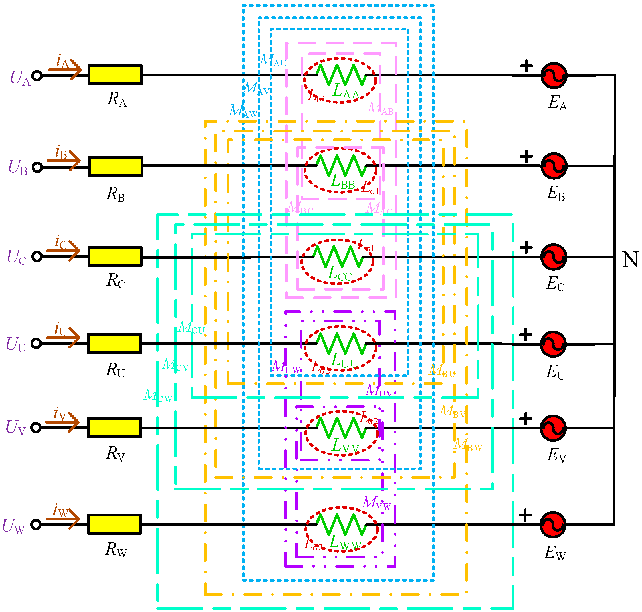
To study the state equation of CSPM motor in three-phase stationary coordinate system, the equivalent circuit diagram of CSPM motor is shown in
Figure 3. Here,
UA,
UB,
UC,
UU,
UV,
UW is the voltage of three-phase stator winding and inner rotor winding;
iA,
iB,
iC,
iU,
iV,
iW is the current of three-phase stator winding and inner rotor winding, and
RA,
RB,
RC,
RU,
RV,
RW is the resistance of them;
LXX is the self-inductance of each phase winding;
MXY is the mutual inductance between different phase windings; and
EA,
EB,
EC,
EU,
EV,
EW is the back EMF produced by the outside and the inside permanent magnet cutting the stator and inner rotor windings.
From
Figure 3, it can be seen that the magnetic circuit parameters of CSPM motor contain resistance, self-inductance, and mutual inductance, which are related to the position and speed of inner rotor and outer rotor, etc. Therefore, the CSPM motor is a nonlinear system with multiple variables, strong coupling, and uncertain parameters. For simplicity, the variables of CSPM motor need to be simplified as follows:
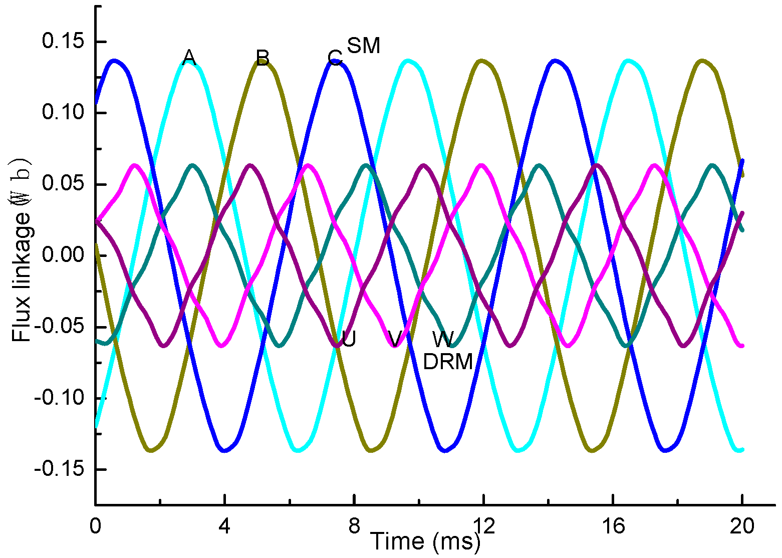
(1) Neglecting magnetic circuit saturation; (2) neglecting eddy current loss and hysteresis effect; (3) The resistance of three phase winding is equal; (4) The back EMF and flux linkage of the stator winding and inner rotor winding, and the flux linkage of permanent magnet, are the sinusoidal waveforms; (5) The distribution of inner and outer air-gap is uniform, and the reluctances of them are constant.
Then, the relationship between the voltage (
U) and the resistance (
R), the current (
I), and the flux linkage (
Ψ) of CSPM motor in the three-phase stationary coordinate system is expressed in Equation (1).
in which
ΨA,
ΨB,
ΨC,
ΨU,
ΨV,
ΨW is the flux linkage of three-phase stator winding and inner rotor winding, which is related to the outer rotor’s position (
θ1), inner rotor’s position (
θ2), current, and the flux linkage of permanent magnet, as shown in Equation (2).
in which
Ψm1 is the flux linkage produced by the outside permanent magnet and
Ψm2 is the flux linkage produced by the inside permanent magnet. The relationship between
LXX and
MXY can be written as
In Equation (3), Lσ1 and Lσ2 is the leakage inductance of outer rotor and inner rotor, respectively; Lσ is the difference between Lσ1 and Lσ2; LV is the average inductance; and L(θ1), L(θ2), L(θ2 − θ1) is the position inductance that is influenced by the position of outer rotor and inner rotor.
Substituting Equation (2) for Equation (1), the new voltage expression of CSPM motor is in Equation (4). The resistance matrix (
R), mutual inductance matrix (
Lm), and the derivative of
Lm (
Lm’) are shown in Equation (5).
in which
ω1,
ω2 is the electric angular velocity of the outer rotor and inner rotor, and
iX’ is the derivative of
iX.
The electromagnetic torque is the partial derivative of magnetic co-energy to the rotor mechanical angle; then, the torque representation of outer rotor (
Tor) and inner rotor (
Tir) can be obtained in Equation (6) based on the virtual displacement method. Here,
Pn is the pole-pair number of CSPM motor,
T1 and
T3 is the electromagnetic torque produced by stator on the outer rotor and inner rotor, respectively. The electromagnetic torque generated by the outer rotor on the outer rotor or produced by the outer rotor on the inner rotor is identical, which is expressed by
T2.
in which
From Equation (6), it can be seen that the torque of outer rotor is related to the current, inductance, and mutual inductance in stator winding and inner rotor winding, flux linkage of permanent magnet, while the torque of inner rotor is involved in the inner rotor current, mutual inductance between the two sets of windings, mutual inductance between stator winding, and inner rotor winding, flux linkage of permanent magnet. The inductance and mutual inductance in stator winding and inner rotor winding are changed with two rotor’s position, and will also be changed when the magnetic field is saturated, which causes the torque ripples of the two rotors [
14,
15]. The current of stator winding and inner rotor winding can also affect the torque ripple. This is because the three-phase current in the two sets windings will produce a rotating magnetic field with three speeds in the outer and inner air-gap, since the magnetic circuit of outer rotor is asymmetrical. If the frequency of stator current is
fs, it will generate a magnetic field with the speeds
n1, (1 − s
1)
n1, and (1 − 2s
1)
n1; s
1 is the transfer rate in SM, while in DRM, the frequency of inner rotor current is
fir, which also produces three magnetic fields in the inner air-gap, i.e.,
n2, (1 − s
2)
n2, and (1 − 2s
2)
n2; s
2 is the transfer rate in DRM. The magnetic field with different speed interactions with each other will result in the torque ripple. These aspects are analyzed in the next part to add the output torque and decrease the torque ripple of CSPM motor.
When CSPM motor operates in the load condition, the flux linkage produced by the stator winding and inner rotor winding current interacts with the flux linkage of inner and outer permanent magnets, then generates the electromagnetic torque on the outer rotor. The electromagnetic torque and load demand torque interact with each other to keep the outer rotor running smoothly. Therefore, the matching between the two currents and permanent magnet size will also affect the output torque performance.
4. Analysis and Optimization of CSPM Motor Based on FEM
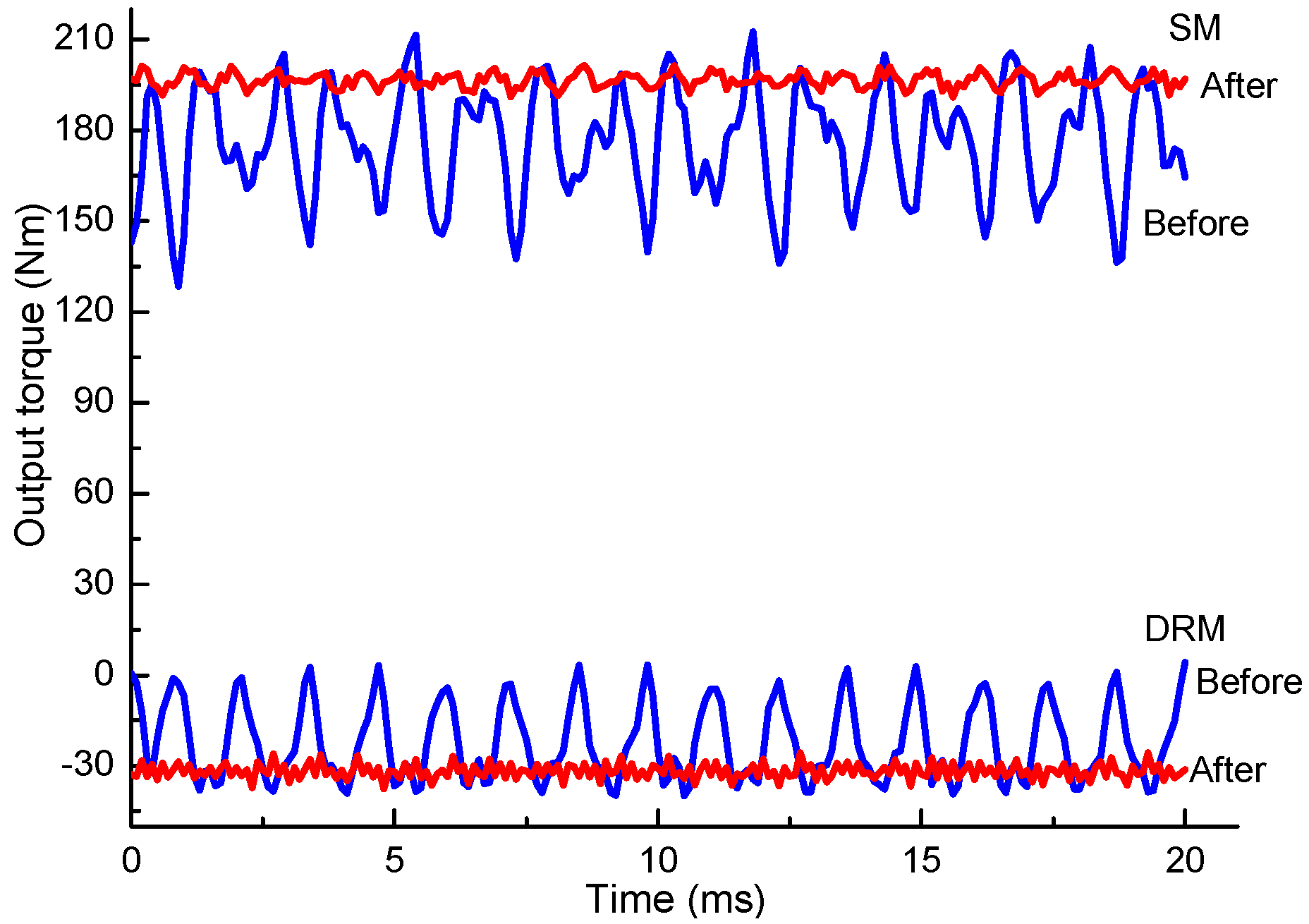
This section studies the torque properties of CSPM motor by optimizing the design of the electromagnetic parameters. The total output torque of CSPM motor is the sum of output torque of SM and DRM, so their torque properties are studied separately.
The analyzed variables used to investigate the torque capabilities are as follows:
- (1)
The variation range of air-gap length is between 0.35 mm and 0.75 mm, and the variable step is 0.05 mm;
- (2)
The variation range of core length is 85 mm to 120 mm, and the variation step is 5 mm;
- (3)
The current frequency of two sets winding changes from 112 Hz to 161 Hz, and the variable step is 5 Hz. The current of stator winding and inner rotor winding is between 150 A and 180 A, and the change step is 10 A.
- (4)
The variation of the polar arc coefficient for permanent magnet is 0.5–0.9, and the step length is 0.05. The current change rule of stator winding and inner rotor winding is as (3);
- (5)
The thickness of permanent magnet varies in the range of 3.5–5.5 mm, and the step length is 0.25 mm. The current also changes as (3);
- (6)
The skewing-slot angle changes from 1 degree to 15 degrees, and the variable step is 1 degree.
- (7)
The percentage of torque ripple (Tripple) is defined as follows:
in which
Tmax is the maximum of output torque in CSPM motor, and
Tavg is the average of output torque.
The detailed analysis process and results are displayed as follows.
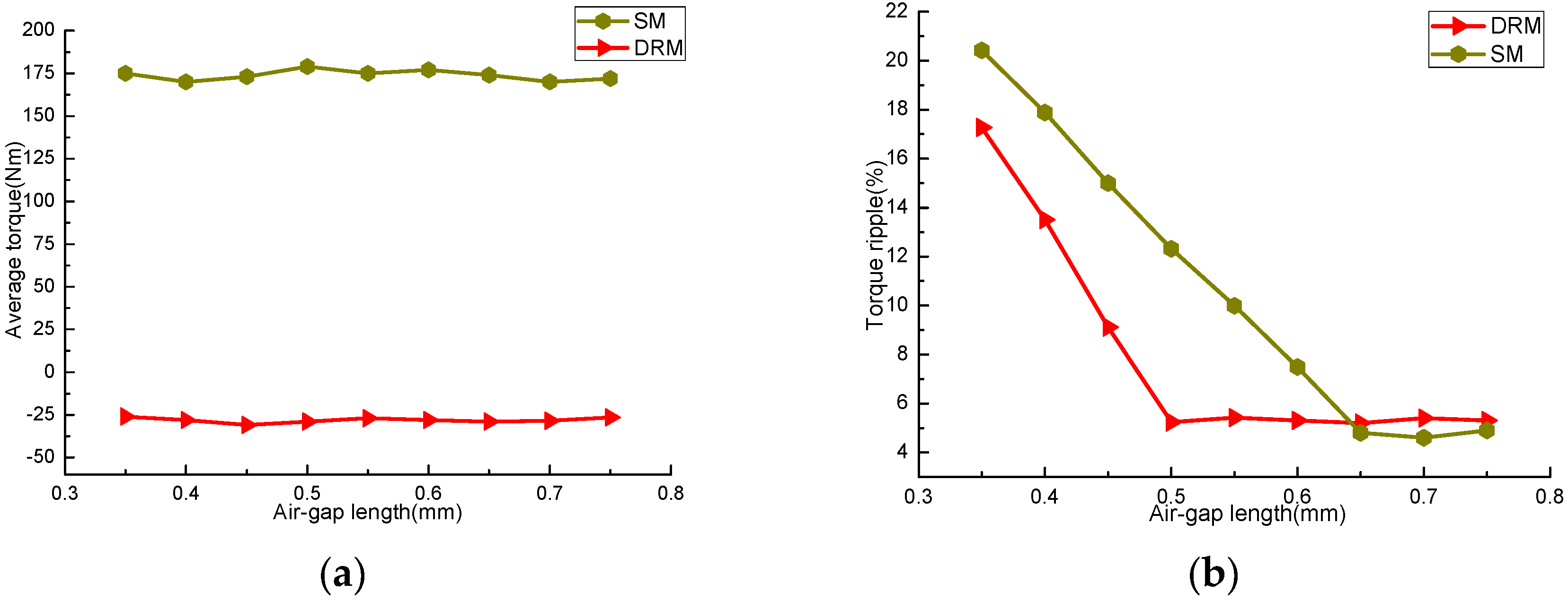
4.1. Air-Gap Length
The air-gap length influences the air-gap harmonic content, and also affects the performance, reliability, processing difficulty, and cost of CSPM motor [
16].
Figure 4 shows the curves of average torque and torque ripple percentage of SM and DRM. The curve of DRM corresponds to the length of inner air-gap, and that of SM relates to the length of outer air-gap.
In
Figure 4a, it can be seen that with the increasing of air-gap length, the average torques of DRM and SM are basically stable. The average torque of DRM is about −26 Nm, and that of SM is around 175 Nm. Positive and negative sign represents the fact that the SM and DRM are working in different states, i.e., electric state or power generation state, while in
Figure 4b, the torque ripple degree of the two machines decreases seriously with the increase of air-gap length, then tends to be stable. The torque ripple of DRM decreases obviously with the increase of air gap length when the inner air-gap length is 0.35 mm–0.5 mm. When the length exceeds 0.5 mm, the fluctuation range is small. The reason is that the smaller air-gap length reduces the installation coaxial degree of CSPM motor, increasing the vibration and noise during operation. For SM, the torque ripple decreases rapidly when the range of outer air-gap length is 0.35 mm–0.65 mm, then changes steadily. Therefore, the torque ripple can be significantly reduced via optimizing the air-gap length, and has small impact on the output torque.
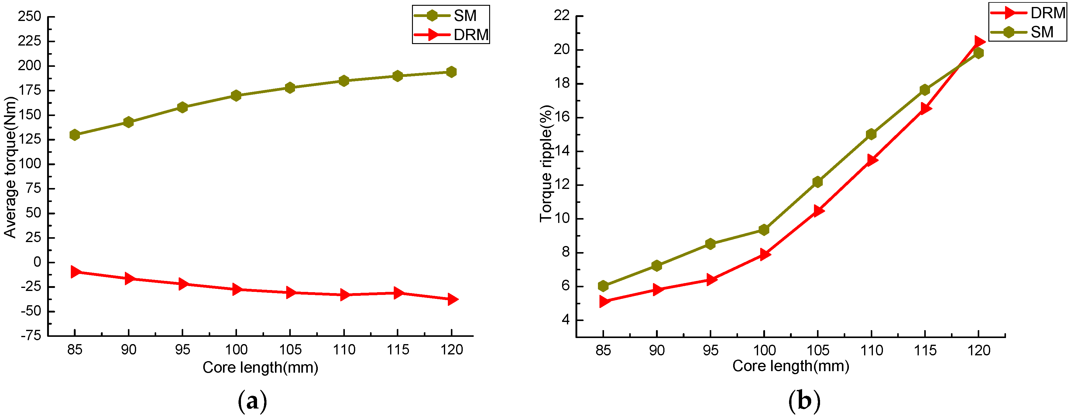
4.2. Core Length
The core length of CSPM motor affects its electromagnetic load. The average torque and torque ripple percentages of SM and DRM with different core lengths are shown in
Figure 5.
Figure 5 shows that, the longer the core is, the larger the average torque is, and the greater the torque ripple is. This is because the raise of core length increases the magnetic flux variation in the two windings, which adds the magnetic co-energy and then increases the average torque of the two machines. The longer core length will also increase the edge flux, which raises the radial magnetic force and the torque ripple. In actual design, the core can be lengthened properly to increase the output torque of CSPM motor. Nevertheless, this method also increases the torque ripple seriously, and the material amount and processing cost will also increase.
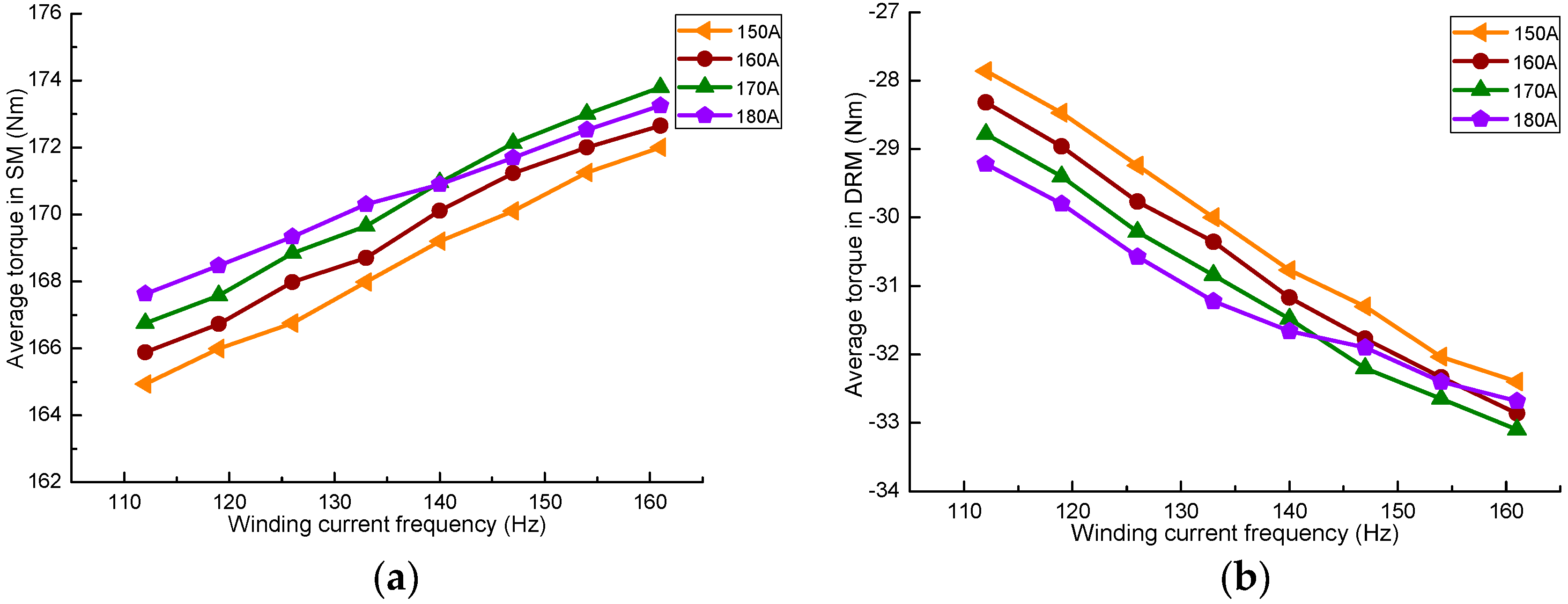
4.3. Different Winding Current Frequency
Figure 6a shows the average torque of SM at different stator winding current frequencies, and
Figure 6b shows DRM at different inner rotor winding current frequencies. One can find that the average torque of the two machines increases with the increasing of current frequency when the current remains constant. This is because the increasing of current frequency reduces the magnetic flux, which decreases the magnetic coupling degree in SM and DRM. Also, it can be found that, under the same current frequency, the average torque of them increases with the current. However, when the current increases to a certain degree, the torque has a declining trend. In
Figure 6a, it can be seen that the average torque of SM when the stator current is 180 A is smaller than the value with the current is 170 A, after the current frequency is more than 140 Hz, while
Figure 6b also features a similar situation. This is because the larger current has increased the magnetic field’s saturation degree. When the magnetic field is oversaturated, the magnetic flux lines flowing in the SM and DRM interfere with each other, which weakens the intensity of the air-gap magnetic field, reducing the torque output capacity.
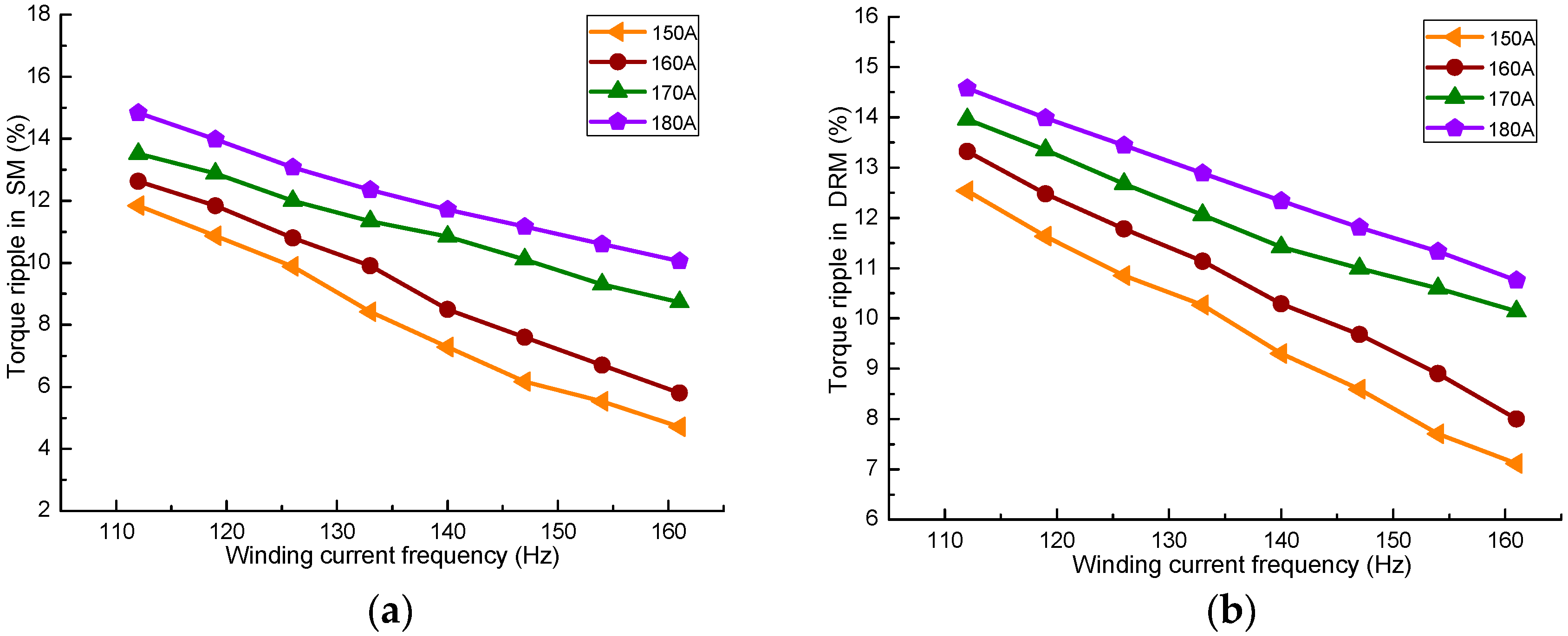
The torque ripple produced by SM and DRM at different currents and current frequencies is given in
Figure 7. It can be known that the torque ripple reductions are correlated with the current frequency adds under the same current. When the current in the two sets of winding is 170 A and 180 A, respectively, the torque declines slower than the currents 150 A and 160 A. This is because the adding of the current causes the magnetic field to reach a saturation state more easily; then, the magnetic circuit parameters will be changed, which impacts the working stability.
4.4. Matching between Permanent Magnet Size and Winding Currents
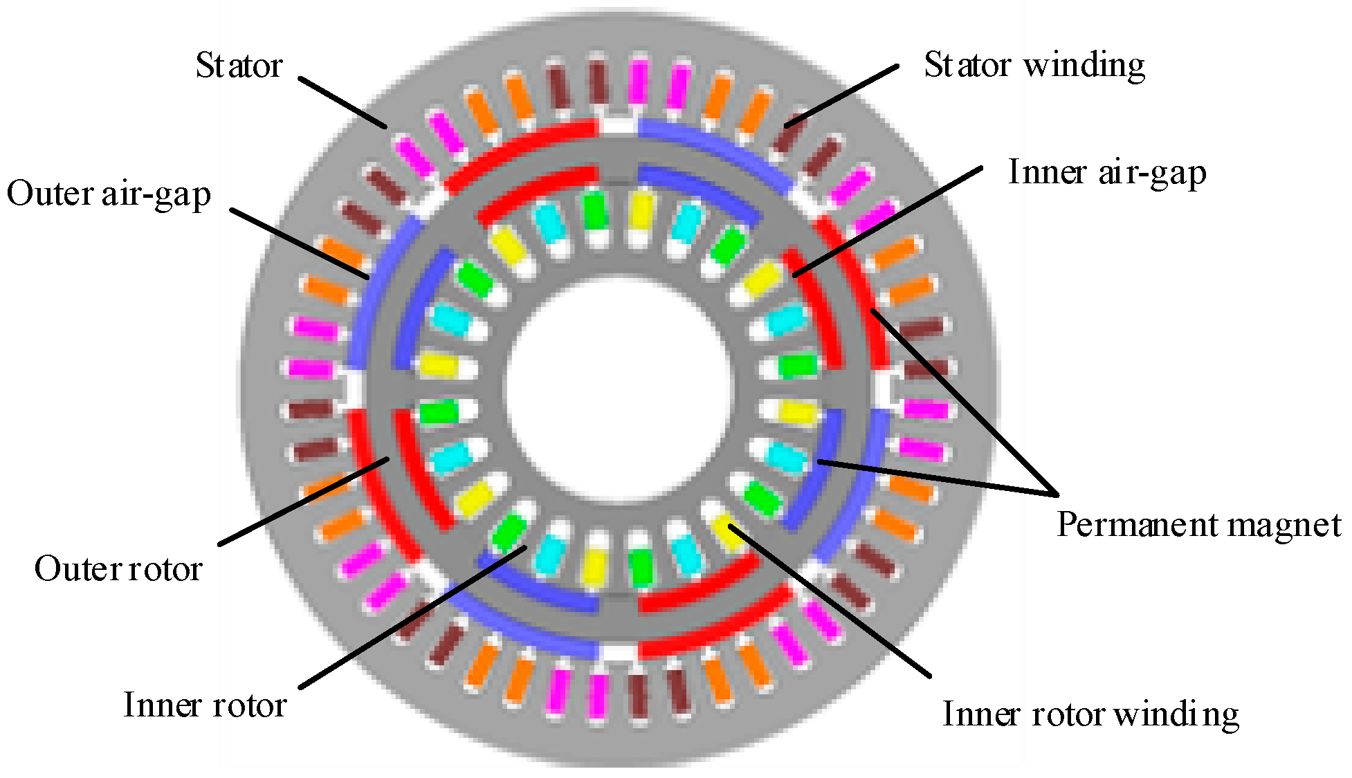
In order to reduce the magnetic field coupling degree between SM and DRM, as well as the size of CSPM motor, the magnetization direction of permanent magnets on both sides of the outer rotor is in the radial direction. The structural dimensions of permanent magnet include axial length, circumferential width, and magnetizing direction thickness. The axial length of permanent magnet is usually the same as the length of the core. This section improves the performance of CSPM motor by optimizing the matching relationship between the two winding currents and the width, the thickness of the permanent magnets.
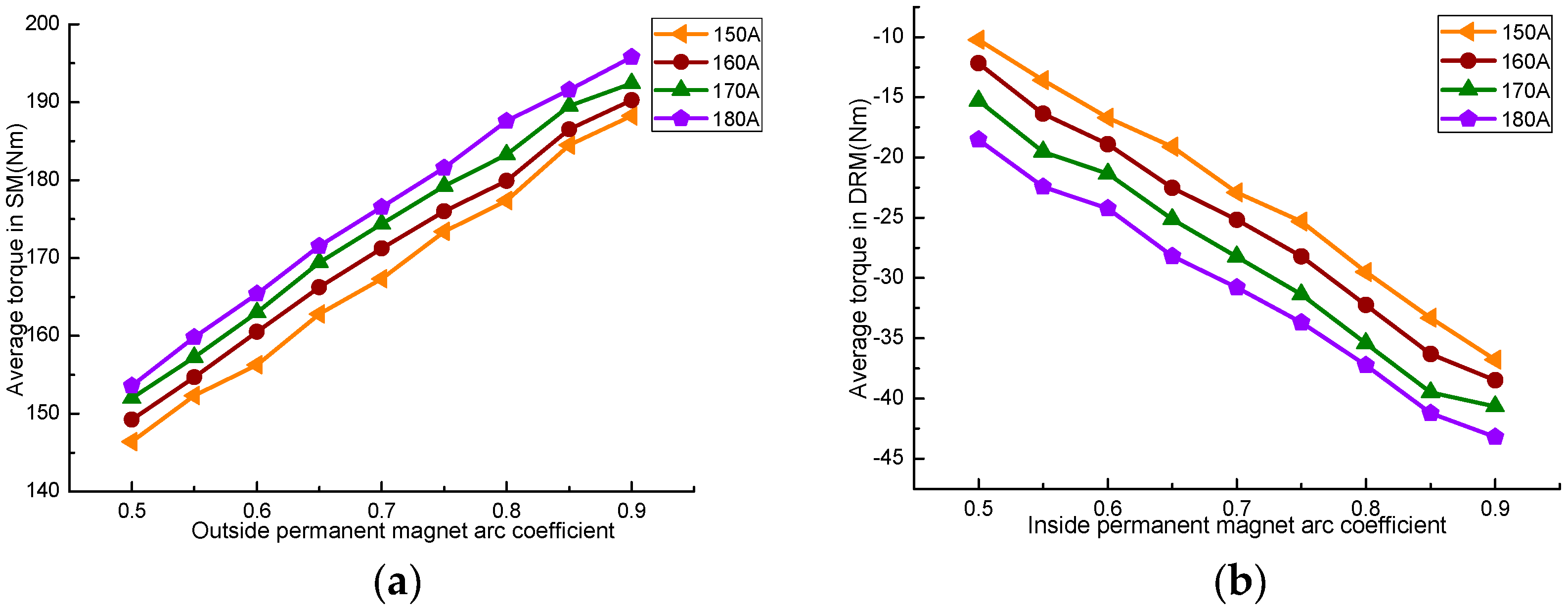
The pole arc coefficient of the permanent magnet is the ratio of the width to pole distance, which affects the magnetic flux per pole, air-gap flux density, the corresponding position between stator slot and outer permanent magnets, and the corresponding position between inner rotor slot and inner permanent magnets. The influence of permanent magnet’s width on the torque characteristics can be studied by changing the pole arc coefficient of it.
Figure 8 is the effect of permanent magnet pole arc coefficient on the average torque.
Figure 8a shows the stator winding current, and
Figure 8b shows the inner rotor winding current.
As can be seen in
Figure 8, the average torque of SM and DRM continually increased with the rise of permanent magnet pole arc coefficient. The main cause is that the increase of pole arc coefficient adds the magnetic flux produced by the permanent magnet, so the total magnetic flux flowing in the SM and DRM also increases. Although the number of stator and inner rotor winding turns is constant, the flux linkage in the two machines also increases, which results in the output torque increasing. The average torque of the two machines also increases with the larger current under the same polar arc coefficient.
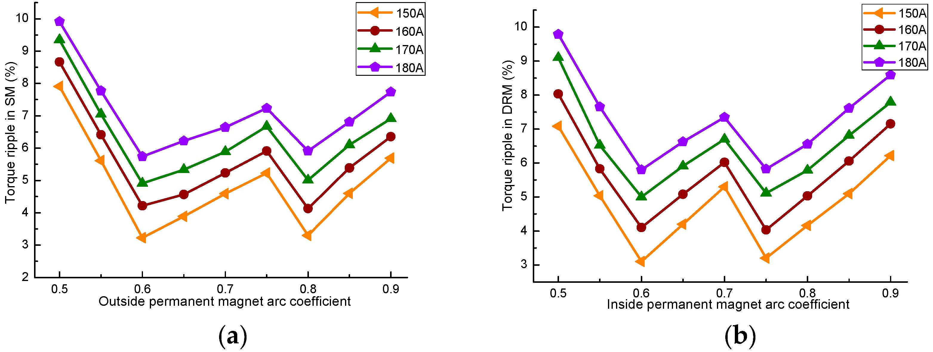
The relationship between the torque ripple and the polar arc coefficient is shown in
Figure 9. It can be observed that the pole arc coefficient of permanent magnet has great influence on the torque ripple. With the increase of pole arc coefficient, the torque ripple of SM and DRM decreases first, then increases, decreases, and, lastly, increases. The torque ripple of SM obtains the minimum when the polar arc coefficient is 0.6 and 0.8, while the DRM obtains the minimum at 0.6 and 0.75. Under the same polar arc coefficient, the torque ripple of SM will increase with the addition of the stator winding current, and that of the DRM will also increase with the increase of the inner rotor winding current.
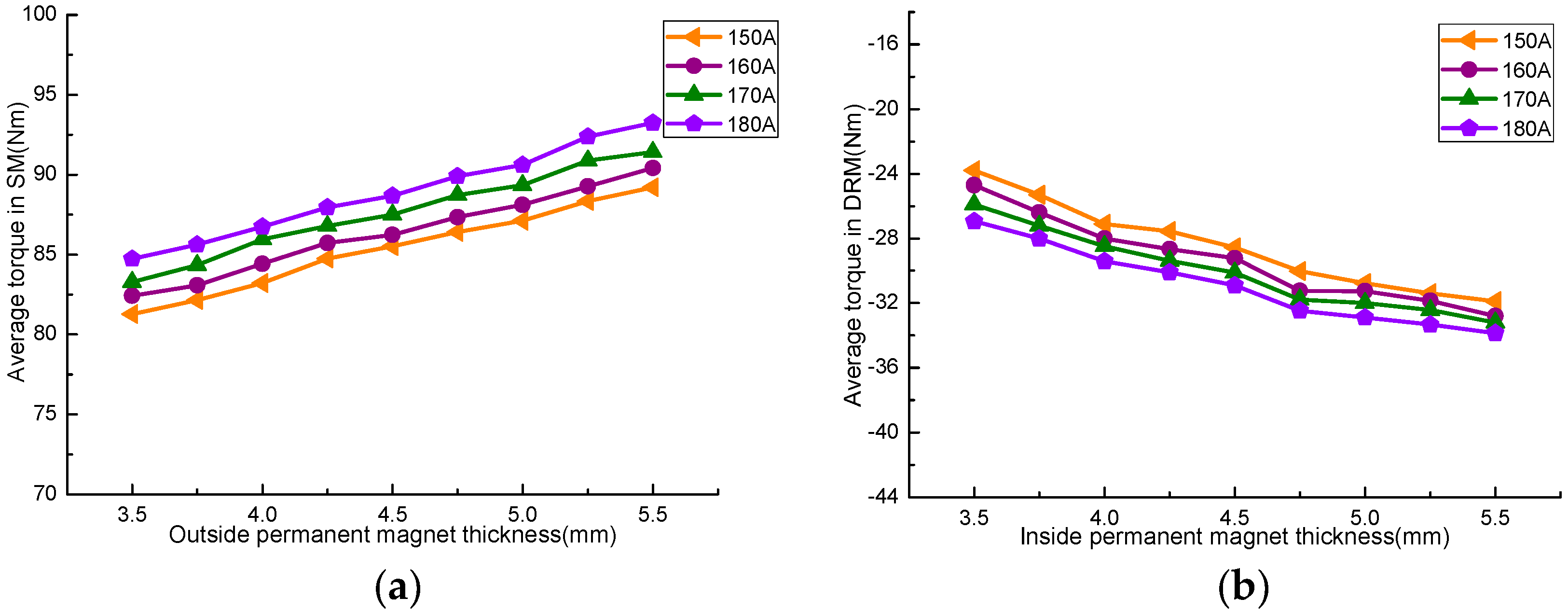
The thickness of the two layers permanent magnet is related to the electrical load, efficiency, and the back EMF waveform of CSPM motor.
Figure 10 gives the average torque of SM and DRM with different thicknesses of permanent magnets.
As seen in
Figure 10, the average torque also increases with the larger permanent magnet’s thickness. However, the effect of permanent magnet’s thickness on the torque value is smaller than that of the width. The increase of the two current excitations also increases the output torque.
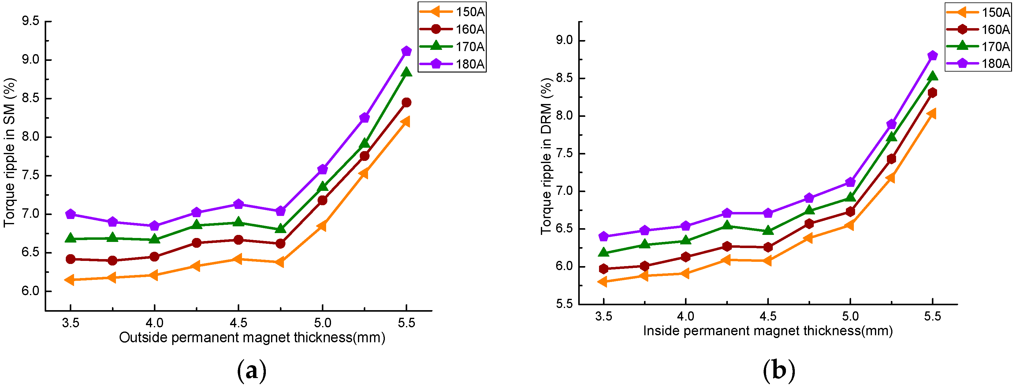
Figure 11 is the relationship of torque ripple between SM, DRM, and permanent magnet thickness.
From
Figure 11, it can be seen that with the increase of the permanent magnet’s thickness, the torque ripple of SM and DRM shows the similar tendency. The increase of the current will increase the torque ripple under the same permanent magnet thickness. The torque ripple increases with the thickness under the same current. This is because the raise of flux produced by the two excitation sources makes the magnetic circuit easy to saturate, then aggravates the output torque fluctuation. When the thickness of SM and DRM is less than 5 mm and 4.75 mm, the torque ripple raises slowly and then increases significantly. The output torque of CSPM motor can be increased by increasing the thickness of permanent magnet properly, but the stability of the torque output will become worse if the thickness is too large.
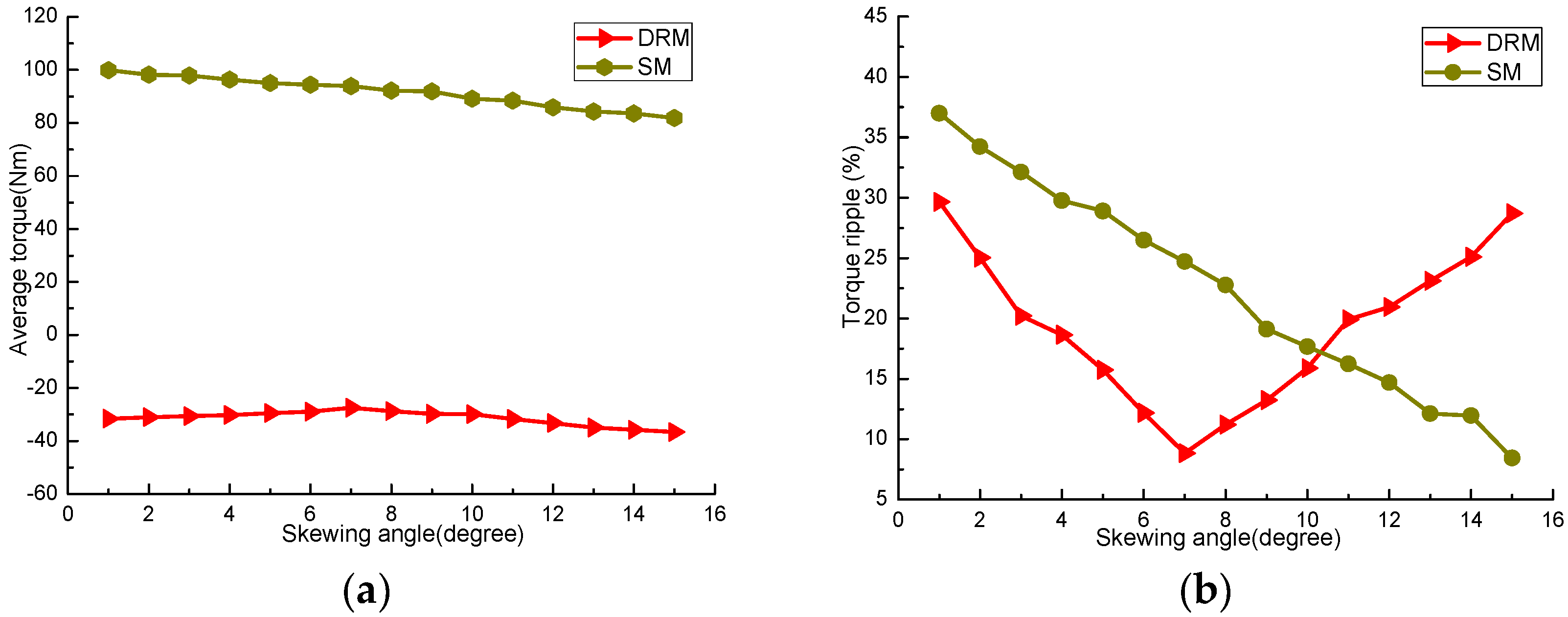
4.5. Skewed Slots
The skewing-slot of stator and inner rotor core can weaken the tooth harmonic potential, optimize the back EMF waveform, and output torque waveform [
17,
18]. The average torque and torque ripple percentages of SM and DRM with different skewing angles are shown in
Figure 12. The skewing angle of stator affects the torque properties of SM, and the skewing angle of inner rotor affects the torque properties of DRM.
From
Figure 12a, it can be seen that the increasing of skewed slot will slightly weaken the output torque. The torque average in SM drops from 100 Nm to 80 Nm within the range of skewing angle. The changing trend of torque in DRM is slightly reduced and then increased, and 7 degrees is the turning point. However, the skewed slot has a good effect on reducing the torque ripple.
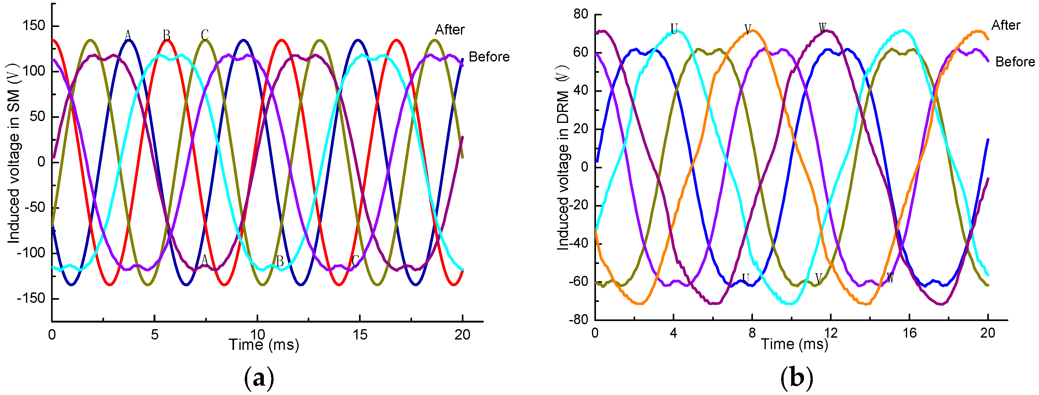
Figure 12b shows that the torque ripple of SM and DRM decreases observably with the increasing skewing angle in stator and inner rotor, but the specific changes are different. The torque ripple percentage of SM continuous declines from 37.3% to 8.6% and achieves the minimum when the skewing angles are 15 degrees. The change curve of torque ripple in DRM is “V” type, and reaches its lowest point when the skewing angles is 7 degrees. The reason is that when the skewing angles of stator and inner rotor are 15 degrees and 7 degrees, respectively, the first order tooth harmonic magnetic field in the two machines can be effectively weakened; then, the air-gap harmonic magnetic field also be decreased. The skewed slot of the stator and inner rotor changes the conductor distribution in the magnetic field. It causes the induced voltage and radial force of every conductor to have a spatial phase difference along the axial direction. Thus, the effective part of the magnetic field will be reduced; then, the coupling action in the SM and DRM will be weakened.


