Abstract
A compact water-cooled thermoelectric generator (TEG) based on a portable gas stove was designed and analyzed to supply electricity in off-grid scenarios. The TEG incorporates a newly designed heat collector, eight thermoelectric (TE) modules, and a radiator to ensure its portability (5.9 kg) and sufficiency of electric power (12.9 W). Detailed measurements and discussions on power load feature and TE efficiency are presented. Experiments showed that the power generation capability of the proposed TEG is compromised by its compactness over previous water-cooled TEGs. A theoretical model incorporated with heat leaks from various origins has been developed to illustrate that the designed TEG exerts the potential of every TE module, and to reveal the proportion of various heat fluxes. The predicted electric power, various heat fluxes, and TE efficiency agree well with experimental data. The limitations of TE efficiency and the nonlinearity caused by Joule heat are discussed quantitatively.
1. Introduction
Human civilization has never progressed like it has currently. However, 1.1 billion people remain without access to electricity [1], and natural disasters frequently cut off the electricity supply in developed regions. In addition, outdoor living highlights the problem of electricity supply. The use of electricity for communication, medical electronic devices, lighting, and other basic necessities in off-grid areas and under emergency conditions (earthquake, hurricane, tidal wave, and military field) is crucial.
Several power-generating technologies, such as solar photovoltaics (SPV) and wind-driven generators are promising solutions but are weather dependent. Recently, thermoelectric generator (TEG) technology has attracted increasing attention because this technology only requires minimal maintenance and is independent of weather. The working principle of a TEG is the Seebeck effect, that is, the temperature difference forces electrons to move in one direction between two metals or semiconductors, thereby resulting in a continuous current through a complete circuit. A TEG requires a heat source, and stoves are ideal. Therefore, a stove-powered TEG (SPTEG) is a promising solution in the above-mentioned scenarios.
It has to be mentioned that the TEG is not the only method of waste heat recovery that can be suitable for stoves. Other technologies, such as organic Rankine cycle [2] and thermo-chemical recuperation, [3] can be considered. These technologies are intensively developed and have proved to be effective. However, they are not within the scope of the present work.
Hundreds of millions of portable gas stoves are sold every year worldwide. Portable gas stoves are convenient to use and produce minimal soot during combustion. Therefore, portable gas stoves are environmentally friendly even though they are based on butane. Other stoves, such as biomass stoves burning twigs or charcoals, are also widely used. Drawbacks of the SPTEG include high cost and low efficiency. The high cost of SPTEG can be reduced by extensive production, while the low efficiency issue can be solved by new thermoelectric (TE) materials [4,5,6,7].
The TEG has been investigated extensively in previous studies [8,9,10,11]. In the present work, only studies that focus on the SPTEG are reviewed and discussed. Previous SPTEG works classified two groups, namely, air- and water-cooled SPTEGs.
Several air-cooled SPTEGs have been developed [12,13,14,15,16,17,18,19,20,21]; among these SPTEGs, up to 12 TE modules can be incorporated to generate 7.8 W electric power [19,20]. Natural draft convection cooling [12,13,14,19,20] and forced draft air cooling [15,16,17,18,21] can be adopted. Forced draft air cooling has been attracting increasing attention in recent years given the drawbacks of the natural draft convection cooling, that is, a relatively large volume and mass weight [21]. Water-cooled SPTEGs have been proposed considering the large heat capacity of water [22,23,24,25,26]. Over 27 W electric power can be generated by a water-cooled SPTEG working at a temperature difference of 250 °C [25,26]. A combined heat and power (CHP) concept has been proposed in water-cooled SPTEGs [23,24,25,26]. CHP provides electricity and hot water simultaneously. Detailed literature reviews on the SPTEG can be found in our previous work [27] and recent review papers [28,29].
The survey of the above literature provides valuable explorations, and the present work is conducted on the basis of these previous works. Several aspects, which are not studied in the above-mentioned literature and will be explored in the present work, are discussed as follows.
- (1)
- There are many previous SPTEGs based on biomass burners and furnaces, yet few previous SPTEGs are based on a portable gas stove. Portable gas stoves are used extensively worldwide. Thus, a SPTEG based on portable gas stoves is obviously required.
- (2)
- A compact water-cooled SPTEG should be developed. Large water tanks are used in previous water-cooled SPTEGs [22,23,24,25,26], whereas no radiators and blowers have been incorporated. The heat flux from the cold end must dissipate into the surrounding air eventually. Therefore, the water tank must be sufficiently large, and water temperature must be sufficiently high for the heat flux from the cold end to be equal to the natural heat dissipation rate from the water tank and pipes. However, using a large water tank causes a large volume and mass weight. Moreover, the CHP concept not only provides warm water but also supplies warm air.
- (3)
- The TE efficiency of the SPTEGs should be explored further. In the air-cooled SPTEGs, only one work has presented a theoretically estimated TE efficiency [14]. In the water-cooled SPTEGs, two works have offered an estimated TE efficiency [24] or measured data [26]. Therefore, further measurements of the TE efficiency are required.
- (4)
- A theoretical analysis should be performed to examine whether the SPTEG exerts the potential of every TE module or not. A well designed SPTEG should be capable of generating electric power maximally, that is, the product of TE module number and the electric power for each module. In particular, the electric power loss should be avoided when paralleling the TE modules. Furthermore, the theoretical analysis helps in quantifying various heat fluxes and revealing the underlying parameters that limit the TE efficiency.
In the present work, a compact water-cooled SPTEG based on a portable gas stove is designed. The TEG incorporates a newly designed heat collector, eight thermoelectric (TE) modules and a radiator to ensure its portability and sufficiency of electric power. The mass weight of the SPTEG, including the portable gas stove and a gas cylinder, is 5.9 kg. The TEG unit can be detached from the portable gas stove. The maximum total electric power output is 12.9 W, where 6.9 W can be used by external loads at a constant voltage of 5 V, at the temperature difference of 119 °C. Over 530 W of clean heat (heated air from the radiator) can be used when the CHP is considered. The power load feature and TE efficiency are studied experimentally and theoretically in detail. The present work offers new experimental data on water-cooled SPTEGs and presents a novel prototype of the SPTEG based on the portable gas stove.
2. Methodology
2.1. SPTEGConfiguration
The SPTEG configuration, experimental setup, photograph of the SPTEG, and electricity circuit are illustrated in Figure 1. The SPTEG consists of a portable gas stove and a TEG unit. The portable gas stove with dimensions of 340 mm×260 mm ×80 mm is bought from the open market, and the fuel of the gas stove is butane. No special effort was taken to operate the gas stove; therefore, the performance of the potable gas stove was not investigated in the present work. The TEG unit includes one inverted U-shaped copper heat-conducting plate, eight TE modules, two aluminum-alloy water-cooled heat sinks, a water pump, an aluminum-alloy radiator, two air blowers, a water container, two electric energy testers (EET), and two DC-DC converters (DDC). The gas stove can be detached from the TEG unit, thereby maintaining its cooking functionality.
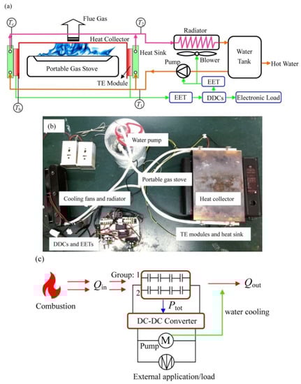
Figure 1.
Developed stove-powered thermoelectric generator (SPTEG) based on a portable gas stove. (a) SPTEG configuration and experimental setup (b) Photograph of the SPTEG (c) Electric circuit.
The inverted U-shaped copper heat-conducting plate had a dimension of 344 mm × 210 mm × 74 mm × 2 mm (length × width × height × thickness). The two “ears”, that is, the vertical parts of the left/right side of the heat-conducting plate, offered smooth flat plates where the TE modules were installed. Eight Bi2Te3 based TE modules were installed, that is, two groups with four TE modules on each ear or group. The TE modules inside a group were wired in series, whereas the two groups were wired in parallel. The dimensions and physical properties of the TE module from the manufacturer are summarized in Table 1. A water-cooled heat sink with a dimension of 40 mm×12 mm×200 mm (length) was installed adjacent to each group of TE modules. All the contact surfaces between the TE modules and the heat-conduction plate/heat sinks were filled with thermal grease with a thermal conductivity of 4.15 W/m·K. Eight bolts (four in each group) were used to fix the above-mentioned components. A water pump was used to circulate the cooling water between the heat sinks and the radiator, and a water container (3 L) was placed between the radiator and the water pump. The heat flux from the cold end must dissipate into the surrounding air; therefore, two air blowers were installed on the radiator. The 18-channel finned radiator had a dimension of 300 mm×140 mm × 15 mm (thickness), and the total surface area of the radiator was 1.04 m2. A JUWEI J7-7 EET (JuNeng XinDi Electronic Technology Co., Ltd., Shenzhen, China) was connected between the TE groups and the DDCs. Another EET was installed between a DDC and the internal loads (the water pump and air blowers). Two tunable DDCs (type XL4016E (JuNeng XinDi Electronic Technology Co., Ltd., Shenzhen, China) were adopted to stabilize the output voltage at the required voltage (5 V at the present work).

Table 1.
Dimensions and physical properties of the thermoelectric (TE) module, fixing bolts and air.
2.2. Experimental Setup and Error Analysis
Thermal images by a Dali T8 thermal imager (DALI Technologies, Hangzhou, China) showed that the temperature distributions on these ears were even. This outcome is predictable given its symmetrical configuration. Four type K thermocouples were installed to measure the temperature difference of the TE module. The thermocouples were located in the middle points of each ear and were installed near the hot/cold sides of the TE module. Another two thermocouples were used to measure the temperature difference of the water after passing through the heat sinks. The measuring range and accuracy of the thermocouples were −200 °C–400 °C and ±0.5%, respectively. The temperature signals were recorded by an Agilent-34970A (Agilent Technologies, Santa Clara, CA, USA) data-acquisition instrument combined with a Benchlink data logger program. The power load feature was measured using a Prodigit 3311F (Prodigit Technologies, New Taipei City, China) electronic load. Its measuring range and accuracy were 0–60 V (300 W) and ± 0.5%, correspondingly. he measuring ranges of the EET were 1 V ≤ U ≤ 100 V and 0 A ≤ I≤ 15 A, whereas the accuracy of the EET was 0.1%.The errors of the measured parameters are listed in Table 2.
Table 2.
Errors of the measured parameters.
2.3. Experimental Procedure
The schematic of an electric circuit of the proposed SPTEG is depicted in Figure 1c. The heat-conducting plate collects thermal energy (Qin) from the flame, which is transferred into the electric power (Ptot) by the TE modules and the heat dissipation to the cold end (Qout). The efficiency of the DDC (ξDDC) varied dynamically, and separate experiments were conducted to determine the efficiency profile of the DDC. The results are demonstrated in Figure 2. The ambient air temperature varied between 4 °C and 6°C during the experiments. The operation procedure for the experimental test includes several steps as follows. Step 1: The TEG unit is placed on the portable gas stove, and the water container is filled with enough water (>1 L). Step 2: The gas stove is switched on. Step 3: The experimental tests are conducted when the SPTEG has reached the steady state. Step 4: The gas stove is turned off.
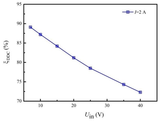
Figure 2.
Transform efficiency of the DC-DC converters (DDC) (Uld = 5 V).
3. Results and Discussions
3.1. Power Load Feature
External electronic devices and batteries have their rated input voltage, and 5.0 V is used widely in small electronic devices. Therefore, the output voltage of the proposed SPTEG was set to 5.0 V. The maximum power point tracking (MPPT) DDC is well recognized to be important in SPV and has also been used in SPTEG studies [24,25,26]. In the present work, a regular DDC was selected instead of an MPPT DDC for the following reasons: (1) The present experiments provide experimental data to select a mating combination of the MPPT DDC and battery. (2) A tunable MPPT DDC can be obtained widely in open market, and the proposed SPTEG is prepared to adopt a mating combination of the MPPT DDC and battery. However, the present work does not focus on the MPPT DDC.
The power load feature test helps to reveal the power generating performance, that is, the potential of the designed SPTEG. The hot end temperature (Th), temperature difference (ΔT), input voltage (Uin), load voltage (Uld), load current (Ild), load electric power (Pld), and total electric power (Ptot,), under different external load resistances are exhibited in Figure 3. The electric power output was stable for 5 min before recording. The temperature difference ranges from 117 °C to 119 °C during the experiments, thereby resulting in the input voltage that lies between 13.1 V and 18.3 V. The decreasing trend of the input voltage while the load resistance decreases is caused by the ratio of the external load resistance to the total electrical resistance, whereas the open-circuit voltage of the SPTEG is unchanged. This result will be explained mathematically in Section 3.3.
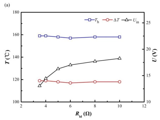
Figure 3.
Results of the power load test of the SPTEG. (a) Hot end temperature, temperature difference, and input voltage of the DDC (b) Load voltage, load current, load electric power, and total electric power.
The load and total electric power increase while the external load resistance decreases. However, the external load resistance should not be significantly small enough to cause unstable output voltage, that is, the output voltage cannot be maintained at 5.0 V. In Figure 3, the maximum total electric power was12.9 W when the load resistance was fixed at 3.5 Ω, whereas the corresponding load electric power was6.9 W (Uld =4.92 V, Ild =1.41 A). The difference between the total and the load electric power (6.0 W) comprise the electric power consumed by the water pump, DDCs, EETs, blowers for the radiator, and all other line losses. Most small electronic devices have a rated current of 1.0 A at 5.0 V (5 W). Consequently, an hour running of the proposed SPTEG with an appropriate DDC and a battery ensures 1.38 h of charging at the charging power of 5 W. The decreasing trend of output power while the load resistance increases is also explained in Section 3.3.
A few studies have conducted a power load test [14], and real-time measurements of electric power output are also rare [23,24]. In general, the power generation should be based on measurements directly on the external loads, such as electronic devices, batteries, and electrical loads. Moreover, the electric power output should be held stable for a sufficiently extended time considering the popular Peltier effect. The transform efficiency of the DDC or MPPT DDC should be measured before further characterizing the SPTEG performance. If a battery is used, then proper caution should be taken because the battery may not accept all the electric power despite incorporating an MMPT DDC. The power load test that uses an electronic load is suggested to measure the SPTEG performance because the electronic load accepts all the provided electric power.
The experimental data can be used to select MPPT DDCs and batteries after performing the power load test on the basis of an electronic load. Furthermore, several previous SPTEGs have operated at a relatively high operating temperature (higher than 200 °C) [25,26]. The wearing out of the Bi2Te3 material should be addressed.
The electric power output generated by each TE module per unit temperature difference (PTE/ΔT) is compared with that of the available previous studies, displayed in Figure 4. The water-cooled SPTEGs provide a larger PTE/ΔT than the air-cooled SPTEGs. However, this result should be evaluated carefully because the heat flux from the cold end must dissipate into the surrounding air. In particular, the water-cooled SPTEG can be cooled by air eventually while the cooling water is circulating. All the reported results in Figure 4 were measured with air-cooled SPTEGs or circulated water-cooled SPTEGs.
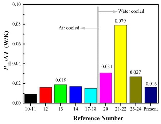
Figure 4.
Comparisons of the electric power by each thermoelectric (TE) module per unit temperature difference.
In Figure 4, the maximum record of PTE/ΔT is 0.019 W/K for an air-cooledSPTEG [15]. However, the minimum datum of PTE/ΔT is 0.027 W/K for a water-cooledSPTEG [25,26], which is obviously larger than that by an air-cooled SPTEG. This divergence should be evaluated sensibly because the Seebeck coefficient and electrical resistivity for Bi2Te3 are nearly the same for available TE modules. This relationship will be discussed in detail in Section 3.3, which focuses on the theoretical aspect of the proposed SPTEG. The water-cooled SPTEGs presented in Figure 4 use water tanks and circulating water pumps, but did not utilize a blower. Therefore, the heat dissipation into the surrounding air is the natural air convection from the walls of the water tank and pipes. The divergence illustrated in Figure 4 is unknown and requires further studies. A possible reason for the divergence may be caused by the large volume of the water tank, that is, the area for natural convection is large, whereas the heat flux from the cold end is limited (limited TE modules are incorporated). Therefore, the water-cooled SPTEG works similar to the SPTEG based on no water circulation. In particular, the circulated water is sufficiently cold given the large water tank. If the volume and mass weight of the water-cooled SPTEG are considered, then radiators and blowers should be used, and the present works should act as an initial attempt. In Figure 4, the power generation capability, that is, PTE/ΔT is only 0.016 W/K for the proposed SPTEG, must be downgraded to be compact and light for the water-cooled SPTEG. The proposed SPTEG demonstrates advantages, such as avoiding installation of the heavy and large finned heat sinks on the TE modules, over the air-cooled SPTEGs.
Another advantage is the possible CHP. The heated air from the radiator supplies clean heat. Moreover, the radiator can be placed indoor, while the stove is running outdoor, thereby ensuring no pollution indoor. However, the CHP is not focused on in the present work.
3.2. TE Efficiency
The TE efficiency can be determined by the following equation:
where Qout is the heat flux from the cold end. The TE efficiency measures the electric power conversion ratio with respect to the heat energy absorbed by the TE modules. Therefore, the TE efficiency is not based on the heat energy released by the fuel. This condition implies that the heat collector is vital in a TEG. In Equation (1), the essential problem becomes the determination of the heat dissipation rate by the cooling water, which can be derived in accordance with the following equations:
where m is the mass flow rate of cooling water and is measured using the weighing method, that is, m = 0.0195 kg/s on average (0.950 kg, 1.195 kg, and 1.380 kg of cooling water in 50, 60, 70 s, correspondingly). The inlet and outlet water temperatures are 31.5 °C and 38.0 °C, respectively. Consequently, the heat dissipation rate by the cooling water is 532.4 W. The natural convection and thermal radiation heat loss to the surroundings can be estimated by:
where the natural convection heat transfer coefficient (h) is estimated to be 4.5 W/m2·K [30], whereas the emissivity of the aluminum alloy (ε) is estimated to be 0.25 [30].The effective area of the heat sink is 0.0128 m2, and the heat loss is estimated to be 5.34 W. The total heat flux to the cold end can be obtained as follows:
The total electric power, that is, Ptot =12.9 W, is demonstrated in Figure 3. Therefore, the TE efficiency is calculated to be 2.34% at a temperature difference of 119 °C. The measured data for the TE efficiency are displayed in Table 3.
Table 3.
Measured data for TE efficiency.
The TE efficiency can be predicted theoretically by assuming that the figure-of-merit is independent of temperature [31,32].
where the figure-of-merit (Z) is defined in Equation(6).
where α is the Seebeck coefficient, ρ is the electrical resistivity, and k is the thermal conductivity. r is the thermal contact ratio, w is the ratio of ceramic thickness to TE leg, and n is the electrical resistivity ratio. For the TE module adopted in the present work, w=0.516. r and n are estimated to be 0.2 and 0.1, respectively and are used widely for the TE modules with ceramic substrates and type-A configuration [32,33]. L is the length of the TE leg. The figure-of-merits of the P- and N-type TE legs are 1.62 × 10⁻³ K−1 and 1.36 × 10⁻³ K−1 for the present TE module, respectively. Figure 5 presents the influence of Z and L on the TE efficiency. As shown in Figure 5, the length of thermoelectric leg has a minor influence on the TE efficiency, while the figure-of-merits is very important to the TE efficiency. In the present work, the TE efficiency is calculated to be 2.57%, which is consistent with the experiment data (2.34%). There are several possible ways to improve the TE efficiency. First, thermoelectric materials with higher ZT value should be developed [4,5,6,7]. Second, increasing the hot end temperature to 200 °C while maintaining the cold end temperature unchanged results in the TE efficiency of 3.26% (an improvement of 26.8%). However, the aging problem has to be taken into consideration. Third, increasing the radiator size can lower the cold temperature which helps to improve the TE efficiency, yet the additional electric power consumption has to be balanced due to the added flow resistance and cooling fans.
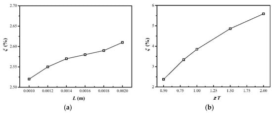
Figure 5.
Influence of Z and L on the TE efficiency when the temperatures are maintained unchanged. (a) Z=1.49 × 10⁻³ K−1 (b) L=1.5 mm.
In Equation(5), the temperature difference is an important parameter for increasing the TE efficiency in addition to the figure-of-merit, thereby implying that the hot end (heat collector) and the cold end (heat sink) should be optimized. In the present work, the heat collector performs well, and its features are as follows:
- (1)
- The heat collector can incorporate a relatively large number of TE modules (eight TE modules in the present work) into a stove while controlling the hot end temperature within a reasonable range, distributing the temperature evenly, and avoiding possible gaps between the TE modules and the heat collector [16].The present heat collector is already in a plate shape, which indicates that no heat spreading plate is required and that gaps can be eliminated from the design. The temperature distribution and interface heat flux are guaranteed by the large thermal conductivity of copper and the symmetry design.
- (2)
- This device avoids large differences of power generation in different TE module groups. This function is important to exert the potential of every TE module. The present heat collector is straightforward but is an appropriately designed copper plate, which ensures that the power generation performance from the two TE module groups is close to each other.
The heat sinks in the present work are regular multi-channel (M shaped channel) heat sinks, which remain to be optimized. However, decreasing the cold end temperature to a low value is unnecessary because the cooling water can be used in a CHP application (supplies clean warmed airs). Furthermore, a multi-stage arrangement of the TE modules [34,35,36] is another means of increasing the TE efficiency.
Limited SPTEG studies have performed TE efficiency testing. Table 4 displays the details of the TE efficiency in the SPTEG studies. In Table 4, the TE material is clearly the major parameter (ZT) to determine the TE efficiency. All SPTEGs have low TE efficiency. However, only a few previous SPTEG studies have conducted such a test in addition to Montecucco’s work [26].
Table 4.
Comparison of TE efficiency with previous studies.
In the present work, the hot end temperature (159 °C) is 41 °C lower than the long-term working limit of the TE module (200 °C), which is the result of thorough optimizations. The experiments reported in the present work were conducted on cold winter days, but the SPTEG should work normally on hot summer days. The ambient air temperature affects the hot end temperature because the heat dissipation is achieved by the radiator, which works with ambient airs. On hot summer days with the air temperature at approximately 40 °C, the hot end temperature of the SPTEG reaches the long-term working temperature limit of the TE module.
3.3. Theoretical Analysis
3.3.1. Theoretical Model Derivation
The Seebeck effect is the working principle of the TE module. The open-circuit voltage of the TE module is as follows:
Peltier effect describes the heat pumping phenomenon, and the amount of heat absorbed or released at a junction is as follows:
where the direction of the current is from P to N. П is the Peltier coefficient. The Thomson heat per unit volume is as follows:
where the direction of the current is positive z. The z-coordinate originates from the cold end of the TE leg, and points to the hot end. μ is the Thomson coefficient. The Joule heat per unit volume is as follows:
For the TE element (leg), the governing equations can be derived on the basis of the energy conservation, first Thomson relation and second Thomson relation. The governing equations can be expressed as follows after treating I as a scalar:
The above mentioned partial equations can be solved under the assumption that the properties (α, ρ, and k) of the TE material are independent of temperature. The obtained result is as follows:
The heat fluxes from and to the hot and cold ends, respectively, are as follows:
The first, second, and third terms on the right-hand side represent the Peltier effect, thermal conductance, and the Joule effect, respectively. The current I is related to the internal electrical and external load resistances. The internal electrical resistance is as follows:
Therefore, the current, the voltage for the external load and the electric power output can be obtained as:
where RE is the external load resistance. Therefore, the voltage for the external load decreases with the external load resistance, whereas the output power increases first.
Heat leaks occur inside the TE module through air heat conduction, thermal radiation, and bolt conduction. This heat leaks can be estimated as follows:
where Ltot is the sum of thicknesses of the heat conducting plate, the TE module, and heat sink.
It has to be mentioned that the present theoretical model acts as an initial attempt to analyze the SPTEG performance. Further works which incorporate high standard computational fluid dynamic methods, such as the Open Foam and the large eddy simulation, should be implemented to study the underlying mechanism of SPTEG.
3.3.2. Power Generation and Heat Transfer
According to the experimental data, Th =159 °C, Tc =40 °C, and their properties are presented in Table 1. The effective temperature difference can be obtained when considering the thermal contact as follows:
where r=0.2 is the typical value for the type-A TE module [32,33]. Consequently, the effective hot and cold end temperatures are 153.5 °C and 45.5 °C, respectively. Therefore, the open-circuit voltage per TE module is calculated to be 5.59 V. Similarly, the electrical resistance of the TE module can be obtained as follows when considering the electrical contact resistivity:
where n = 0.1 × 10⁻³ m is the typical value for the type-A TE module [32,33]. The internal electrical resistance is 4.07 Ω. For the proposed SPTEG, the maximum current is as follows:
where NTE is the number of TE module in each group, and Ng is the group number in the proposed SPTEG (NTE = 4, Ng = 2). The maximum electric power output can be obtained as follows:
The predicted result is 18.6% larger than the experimental data (12.9 W). The possible reason for this error may be caused by the aging problem of the TE module [33]. The analytical model adopts the material properties provided by the manufacturer. However, after anextended runtime (the situation of the present work), the performance of TE module will decrease and then stabilize. Various heat fluxes are then calculated. The results are summarized in Table 5.
Table 5.
Heat fluxes from the hot end and to the cold end.
The measured heat dissipation rate from the cold end is 537.8 W, which is comparable to the predicted data (534.2 W), and the error is 0.7%. Therefore, the TE efficiency is predicted to be 2.78%, which is consistent with the experimental data (2.34%). In Table 5, the heat leak caused by the air conduction and thermal radiation cannot be neglected and accounts for approximately 5% of total heat flux. In addition, the heat leak through the eight bolts accounts for approximately 4% of the total heat flux. Moreover, the net heat rate between the hot and cold ends is 15.4 W, which is consistent with the predicted electric power output (15.3 W). Precise observations find that the difference of the heat flux by the Peltier pumping comprises the power generation when the Peltier pumping is working between two surfaces with different temperatures and a proper direction of the temperature gradient. The comparison between the analytical results and experimental data is shown in Table 6.
Table 6.
Comparison between the analytical results and experimental data.
If no heat conduction (kp = kn = 0 W/m·K) and no heat leak (kair = 0 W/m·K, kbt = 0 W/m·K, and ε = 0) occur, then the TE efficient will not exceed 12.6% under the present hot/cold end temperatures and electrical resistivity. The conductance heat flux accounts for over 70% of the total heat flux. Therefore, the thermal conductivity of the TE material is the main reason for the limited TE efficiency. This condition can be explained by the popular parameter of figure-of-merit (Z), which is defined in Equation (6). However, this equation does not present a quantitative analysis.
3.3.3. Nonlinearity
In Equation (12), the temperature distribution along the TE leg is nonlinear, which is caused by the Joule and Thomson heats. No Thomson heat was considered in the present work because the properties are treated as temperature independent. According to the experimental data, Th,eff = 153.5 °C, Tc,eff = 45.5 °C, and the maximum current inside a TE module is as follows:
The temperature distribution along the leg is exhibited in Figure 6. The maximum difference between the analytical temperature and the corresponding linear result is 0.51 °C. Therefore, the nonlinearity induced by the Joule heat is minor for the present TE material.
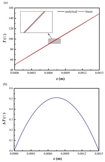
Figure 6.
Temperature distribution under the maximum current. (a) Temperature distribution along the leg (b) Temperature difference between the analytical temperature and the corresponding linear result along the leg.
3.3.4. Discussions on the Heat Flux Prediction
Thorough observations in the literature find that the thermal conductivity for the Bi2Te3 is different in various references. If thermal conductivities are treated as temperature-independent properties, then kp varies between 1.265 W/m·K and 2.4 W/m·K, whereas kn varies from 1.011 to 2.4 W/m·K [37,38,39,40,41]. Moreover, the magnitude of the thermal conductivity is far larger than the Seebeck coefficient and electrical resistivity. Thus, the accuracy of thermal conductivity is an essential issue for predicting the heat flux from the hot end or to the cold end. The thermal conductivity (kP = 1.68 W/m·K, kN = 1.64 W/m·K) of the present TE module is normal compared with that of previous studies [37,38,39,40,41].
Thermal conductivity, Seebeck coefficient, and electrical resistivity are temperature-dependent. However, a severe divergence can be found [42,43,44,45], that is, the thermal conductivity varies between 0.8 and 2.7 W/m·K. If the properties are treated as temperature-dependent, then the exact analytical solution of Equation (11) cannot be obtained. Several works focus on this aspect [46,47,48,49,50], thereby providing interesting findings. However, the predicted results with constant properties provide comprehensive predictions. The errors caused by using constant properties are bearable from an engineering perspective.
4. Conclusions
A compact water-cooled TEG based on a portable gas stove was proposed and investigated experimentally and theoretically. Power load tests were conducted, and the results were compared with those of various previous studies. The theoretical aspect was explored by focusing on the power generation, various heat fluxes, and nonlinearity caused by the Joule effect. Several conclusions can be drawn based on the analysis of the results.
- (1)
- The designed SPTEG can generate the potential of every TE module. The maximum electric power of 12.9 W, where 6.9 W can be outputted to external loads at the voltage of 5.0 V, can be generated. The gas stove can be detached from the TEG unit, thereby maintaining the cooking nature of the gas stove.
- (2)
- The radiator and blowers help in making the SPTEG compact, but the total electric power generation is compromised. The advantages of the proposed compact water-cooled SPTEG include possible CHP applications and avoidance of heavy and large finned heat sink installations on the TE modules.
- (3)
- Various heat fluxes through the TE modules were explored theoretically. The results indicate that the thermal conductance accounts for over 70% of the total heat flux. The thermal leak by the air heat conduction and thermal radiation inside the TE modules and by the fixing bolts are significant.
- (4)
- The nonlinearity caused by the Joule heat is minor, and the temperature distribution along the TE leg is near linear.
- (5)
- The essential parameter, which affects the prediction of the total heat flux, is the thermal conductivity of the TE materials. The theoretical predict thermoelectric efficiency is 2.78%, which is consistent with the measured data (2.34%).
Author Contributions
Conceptualization, G.L. and H.L.; Methodology, G.L.; Validation, Y.Z. and J.L.; Investigation, H.L. and J.L.; Data Curation, Y.Z. and J.H.; Writing-Original Draft Preparation, G.L. and H.L.; Writing-Review & Editing, G.L.; Funding Acquisition, G.L..
Funding
This work was partially supported by the National Natural Science Foundation of China (Grant Nos. 51476145, and 51476146) and the Distributed High Power STEG Development Program (SGTYHT/17-JS-202).
Conflicts of Interest
The authors declare no conflict of interest.
Nomenclature
| A | Cross-sectional area of the thermoelectric leg (m2) |
| AHS | outside surface area of the heat sink (m2) |
| Atotal | surface area of a TE module (m2) |
| cp | heat capacity of water (J/kg) |
| dbt | bolt diameter (m) |
| H | natural convection heat transfer coefficient (W/m2·K) |
| I | current (A) |
| Ild | load current (A) |
| ITE,max | maximum current inside a TE module (A) |
| Imax | maximum current of the SPTEG(A) |
| K | thermal conductivity (W/m·K) |
| kair | thermal conductivity of air (W/m·K) |
| kbt | thermal conductivity of the bolt (W/m·K) |
| kN | thermal conductivity of the N-type leg (W/m·K) |
| kP | thermal conductivity of the P-type leg (W/m·K) |
| L | length of thermoelectric leg (m) |
| Lcm | thickness of the ceramic substrate (m) |
| Ltot | thickness of the bolt responsible for heat conduction (m) |
| M | mass flow rate of cooling water (kg/s) |
| N | electrical resistivity ratio (m) |
| N | number of thermoelectric couples inside a TE module (dimensionless) |
| Nbt | number of bolts (dimensionless) |
| Ng | number of TE groups in SPTEG (dimensionless) |
| NTE | number of TE modules in a TE group (dimensionless) |
| P | power (W) |
| Pld | load electricity power (W) |
| Ptot | total electricity power (W) |
| Pmax | maximum total electricity power (W) |
| PTE | Electric power generated per TE module (W) |
| qJ | Joule heat flux per unit volume (W/m3) |
| qP | Peltier heat flux at a junction (W) |
| qT | Thomson heat flux per unit volume (W/m3) |
| Qcd | total conductance heat flux of the SPTEG (W) |
| Qin | heat conduction flux through the heat-conducting plate (W) |
| QJ | total Joule heat flux of the SPTEG (W) |
| Qlk,cod | total conduction heat leak inside the TE module (W) |
| Qlk,rad | total thermal radiation heat leak inside the TE module (W) |
| Qlk,bt | total conduction heat leak by the bolts (W) |
| Qloss | total heat lost by natural convection and thermal radiation (W) |
| QP | total Peltier heat of the SPTEG (W) |
| Qout | heat flux from the cold end (W) |
| Qtot | total heat flux (W) |
| r | thermal contact ratio (dimensionless) |
| RI | internal electrical resistance (Ω) |
| RI,eff | effective internal electrical resistance (Ω) |
| RE | external electrical resistance (Ω) |
| Rld | load resistance (Ω) |
| T | temperature (°C) |
| T1 | inlet water temperature (°C) |
| T2 | outlet water temperature (°C) |
| Tc | cold end temperature (°C) |
| Th | hot end temperature (°C) |
| T∞ | ambient air temperature (°C) |
| ΔT | temperature difference (°C), ΔT= Th − Tc |
| ΔTeff | effective temperature difference (°C) |
| U | voltage (V) |
| UE | voltage of the external load (V) |
| Uin | input voltage to the DDC (V) |
| Uld | load voltage (V) |
| VOC | open-circuit voltage (V) |
| w | ratio of ceramic thickness to thermoelectric leg (dimensionless) |
| z | z coordinate (m) |
| Z | thermoelectric figure-of-merit (1/K) |
| α | Seebeck coefficient (V/K) |
| αN | Seebeck coefficient of the N-type leg (V/K) |
| αP | Seebeck coefficient of the P-type leg (V/K) |
| ρ | electrical resistivity (Ω·m) |
| ρN | electrical resistivity of the N-type leg (Ω·m) |
| ρP | electrical resistivity of the P-type leg (Ω·m) |
| ε | emissivity of the ceramic substrate (dimensionless) |
| Σ | Stefan-Boltzmann constant (W/m2K4) |
| Ξ | thermoelectric efficiency (%) |
| ξDDC | transform efficiency of the DDC (%) |
| μ | Thomson coefficient (V/K) |
| П | Peltier coefficient (V) |
Abbreviations
| CHP | combined heat and power |
| DDC | DC-DC converter |
| EET | electric energy tester |
| MPPT | maximum power point tracking |
| SPTEG | stove-powered thermoelectric generator |
| SPV | solar photovoltaics |
| TE | thermoelectric |
| TEG | thermoelectric generator |
References
- International Energy Agency. Word Energy Outlook 2017. Available online: http://www.iea.org/weo2017/ (accessed on 1 July 2018).
- Tocci, L.; Pal, T.; Pesmazoglou, I.; Franchetti, B. Small scale organic Rankine cycle (ORC): A techno-economic review. Energies 2017, 10, 413. [Google Scholar] [CrossRef]
- Tartakovsky, L.; Sheintuch, M. Fuel reforming in internal combustion engines. Prog. Energy Combust. Sci. 2018, 67, 88–114. [Google Scholar] [CrossRef]
- Biswas, K.; He, J.; Blum, I.D.; Wu, C.I.; Hogan, T.P.; Seidman, D.N.; Dravid, V.P.; Kanatzidis, M.G. High-performance bulk thermoelectric with all-scale hierarchical architectures. Nature 2012, 489, 414–418. [Google Scholar] [CrossRef] [PubMed]
- Zhao, L.; Lo, S.H.; Zhang, Y.; Sun, H.; Tan, G.; Uher, C.; Wolverton, C.; Dravid, V.P.; Kanatzidis, M.G. Ultralow thermal conductivity and high thermoelectric figure of merit in SnSe crystals. Nature 2014, 508, 373–377. [Google Scholar] [CrossRef] [PubMed]
- Zhao, L.; Tan, G.; Hao, S.; He, J.; Pei, Y.; Chi, H.; Wang, H.; Gong, S.; Xu, H.; Dravid, V.P.; Uher, C.; Snyder, G.J.; Wolverton, C.; Kanatzidis, M.G. Ultrahigh power factor and thermoelectric performance in hole-doped single-crystal SnSe. Science 2016, 351, 141–144. [Google Scholar] [CrossRef] [PubMed]
- Liu, Z.; Mao, J.; Sui, J.; Ren, Z. High thermoelectric performance of α-MgAgSb for power generation. Energy Environ. Sci. 2018, 11, 23–44. [Google Scholar] [CrossRef]
- Ma, H.K.; Lin, C.P.; Wu, H.P.; Peng, C.H.; Hsu, C.C. Waste heat recovery using a thermoelectric power generation system in a biomass gasifier. Appl. Therm. Eng. 2015, 88, 274–275. [Google Scholar] [CrossRef]
- Barma, M.C.; Riaz, M.; Saidur, R.; Long, B.D. Estimation of thermoelectric power generation by recovering waste heat from biomass fired thermal oil heater. Energy Convers. Manag. 2015, 98, 303–313. [Google Scholar] [CrossRef]
- Remeli, M.F.; Date, A.; Orr, B.; Ding, L.C.; Singh, B.; Dalila, N.; Affandi, N.; Akbarzadeh, A. Experimental investigation of combined heat recovery and power generation using a heat pipe assisted thermoelectric generator system. Energy Convers. Manag. 2016, 11, 147–157. [Google Scholar] [CrossRef]
- Kim, T.Y.; Kwak, J.; Kim, B.W. Energy harvesting performance of hexagonal shaped thermoelectric generator for passenger vehicle applications: An experimental approach. Energy Convers. Manag. 2018, 160, 14–21. [Google Scholar] [CrossRef]
- Nuwayhid, R.Y.; Rowe, D.M.; Min, G. Low cost stove-top thermoelectric generator for regions with unreliable electricity supply. Renew. Energy 2003, 28, 205–222. [Google Scholar] [CrossRef]
- Nuwayhid, R.Y.; Shihadeh, A.; Ghaddar, N. Development and testing of a domestic woodstove thermoelectric generator with natural convection cooling. Energy Convers. Manag. 2005, 46, 1631–1643. [Google Scholar] [CrossRef]
- Lertsatitthanakorn, C. Electrical performance analysis and economic evaluation of combined biomass cook stove thermoelectric (BITE) generator. Bioresour. Technol. 2007, 98, 1670–1674. [Google Scholar] [CrossRef] [PubMed]
- Raman, P.; Ram, N.K.; Gupta, R. Development, design and performance analysis of a forced draft clean combustion cookstove by a thermo electric generator with multi-utility options. Energy 2014, 69, 813–825. [Google Scholar] [CrossRef]
- O’Shaughnessy, S.M.; Deasy, M.J.; Doyle, J.V.; Robinson, A.J. Performance analysis of a prototype small scale electricity-producing biomass cooking stove. Appl. Energy 2015, 156, 566–576. [Google Scholar] [CrossRef]
- Mal, R.; Prasad, R.; Vijay, V.K. Design and performance evaluation of thermoelectric generator stove and comparison with traditional, natural and forced draft stoves. Int. J. Energy Policy 2015, 11, 220–233. [Google Scholar] [CrossRef]
- Mal, R.; Prasad, R.; Vijay, V.K. Multi-functionality clean biomass cookstove for off-grid areas. Process. Saf. Environ. 2016, 104, 85–94. [Google Scholar] [CrossRef]
- Najjar, Y.S.H.; Kseibi, M. Heat transfer and performance analysis of thermoelectric stoves. Appl. Therm. Eng. 2016, 102, 1045–1058. [Google Scholar] [CrossRef]
- Najjar, Y.S.H.; Kseibi, M. Evaluation of experimental JUST thermoelectric stove for electricity-deprived regions. Renew. Sustain. Energy Rev. 2017, 69, 854–861. [Google Scholar] [CrossRef]
- BioLite. Available online: https://www.bioliteenergy.com/ (accessed on 3 June 2018).
- Rinalde, G.F.; Juanico, L.G.; Taglialavore, E.; Gortari, S.; Molina, M.G. Development of thermoelectric generators for electrification of isolated rural homes. Int. J. Hydrogen Energy 2010, 35, 5818–5822. [Google Scholar] [CrossRef]
- Champier, D.; Bédécarrats, J.P.; Rivaletto, M.; Strub, F. Thermoelectric power generation from biomass cook stoves. Energy 2010, 35, 935–942. [Google Scholar] [CrossRef]
- Champier, D.; Bédécarrats, J.P.; Kousksou, T.; Rivaletto, M.; Strub, F.; Pignolet, P. Study of a TE (thermoelectric) generator incorporated in a multifunction wood stove. Energy 2011, 36, 1518–1526. [Google Scholar] [CrossRef]
- Montecucco, A.; Silviter, J.; Knox, A.R. A combined heat and power system for solid-fuel stoves using thermoelectric generators. Energy Procedia 2015, 75, 597–602. [Google Scholar] [CrossRef]
- Montecucco, A.; Siviter, J.; Knox, A.R. Combined heat and power system for stoves with thermoelectric generators. Appl. Energy 2017, 185, 1336–1342. [Google Scholar] [CrossRef]
- Li, G.N.; Zhang, S.; Zheng, Y.Q.; Zhu, L.Y.; Guo, W.W. Experimental study on a stove-powered thermoelectric generator (STEG) with self starting fan cooling. Renew. Energy 2018, 121, 502–512. [Google Scholar] [CrossRef]
- Gao, H.B.; Huang, G.H.; Li, H.J.; Qu, Z.G.; Zhang, Y.J. Development of stove-powered thermoelectric generators: A review. Appl. Therm. Eng. 2016, 96, 297–310. [Google Scholar] [CrossRef]
- Najjar, Y.S.H.; Kseibi, M.M. Thermoelectric stoves for poor deprived regions—A review. Renew. Sustain. Energ. Rev. 2017, 80, 597–602. [Google Scholar] [CrossRef]
- Holman, J.P. Heat Transfer, 10th ed.; Mc Graw Hill: New York, NK, USA, 2008. [Google Scholar]
- Heikes, R.R.; Ure, R.W., Jr. Thermoelectricity: Science and Engineering; Interscience Publishers: New York, NY, USA; London, UK, 1961; Chapters 1 and 15. [Google Scholar]
- Rowe, D.M. CRC Handbook of Thermoelectrics; CRC Press: London, UK, 1995; Chapters 19, 38 and 44. [Google Scholar]
- Rowe, D.M.; Min, G. Evaluation of thermoelectric modules for power generation. J. Power Sources 1998, 73, 193–198. [Google Scholar] [CrossRef]
- Lindler, K.W. Use of multi-stage cascades to improve performance of thermoelectric heat pumps. Energy Convers. Manag. 1998, 39, 1009–1014. [Google Scholar] [CrossRef]
- Arora, R.; Kaushik, S.C.; Arora, R. Multi-objective and multi-parameter optimization of two-stage thermoelectric generator in electrically series and parallel configurations through NSGA-II. Energy 2015, 91, 242–254. [Google Scholar] [CrossRef]
- Chen, K.; Qin, J.; Jiang, Y.; Lv, C.; Zhang, S.; Bao, W. Performance assessment of multi-stage thermoelectric generators on hypersonic vehicles at a large temperature difference. Appl. Therm. Eng. 2018, 130, 1598–1609. [Google Scholar] [CrossRef]
- Nuwayhid, R.Y.; Hamade, R. Design and testing of a locally made loop-type thermosyphonic heat sink for stove-top thermoelectric generators. Renew. Energy 2005, 30, 1101–1116. [Google Scholar] [CrossRef]
- Hsu, C.T.; Huang, G.Y.; Chu, H.S.; Yu, B.; Yao, D.J. An effective Seebeck coefficient obtained by experimental results of a thermoelectric generator module. Appl. Energy 2011, 88, 5173–5179. [Google Scholar] [CrossRef]
- Pérez-Aparicio, J.L.; Palma, R.; Taylor, R.L. Finite element analysis and material sensitivity of Peltier thermoelectric cells coolers. Int. J. Heat Mass Transf. 2012, 55, 1363–1374. [Google Scholar] [CrossRef]
- Ma, Q.; Fang, H.; Zhang, M. Theoretical analysis and design optimization of thermoelectric generator. Appl. Therm. Eng. 2017, 127, 758–764. [Google Scholar] [CrossRef]
- Zhao, Y.; Wang, S.; Ge, M.; Li, Y.; Yang, Y. Energy and exergy analysis of thermoelectric generator system with humidified flue gas. Energy Convers. Manag. 2018, 156, 140–149. [Google Scholar] [CrossRef]
- Riffat, S.B.; Ma, X.; Wilson, R. Performance simulation and experimental testing of a novel thermoelectric heat pump system. Appl. Therm. Eng. 2006, 26, 494–501. [Google Scholar] [CrossRef]
- Chen, W.H.; Wang, C.C.; Hung, C.I.; Yang, C.C.; Juang, R.C. Modeling and simulation for the design of thermal-concentrated solar thermoelectric generator. Energy 2014, 64, 287–297. [Google Scholar] [CrossRef]
- Liao, M.; He, Z.; Jiang, C.; Fan, X.; Li, Y.; Qi, F. A three-dimensional model for thermoelectric generator and the influence of Peltier effect on the performance and heat transfer. Appl. Therm. Eng. 2018, 133, 493–500. [Google Scholar] [CrossRef]
- Lan, S.; Yang, Z.; Chen, R.; Stobart, R. A dynamic model for thermoelectric generator applied to vehicle waste heat recovery. Appl. Energy 2018, 210, 327–338. [Google Scholar] [CrossRef]
- Fraisse, G.; Ramousse, J.; Sgorlon, D.; Goupil, C. Comparison of different modeling approaches for thermoelectric elements. Energy Convers. Manag. 2013, 65, 351–356. [Google Scholar] [CrossRef]
- Ju, C.; Dui, G.; Zheng, H.H.; Xin, L. Revisiting the temperature dependence in material properties and performance of thermoelectric materials. Energy 2017, 124, 249–257. [Google Scholar] [CrossRef]
- Wang, J.; Li, Y.; Zhao, C.; Cai, Y.; Zhu, L.; Zhang, C.; Wang, J.; Zhao, W.; Cao, P. An optimization study of structural size of parameterized thermoelectric generator module on performance. Energy Convers. Manag. 2018, 160, 176–181. [Google Scholar] [CrossRef]
- Wee, D. Uncertainty and sensitivity of the maximum power in thermoelectric generation with temperature-dependent material properties: An analytic polynomial chaos approach. Energy Convers. Manag. 2018, 157, 103–110. [Google Scholar] [CrossRef]
- Lee, H.; Sharp, J.; Stokes, D.; Pearson, M.; Priya, S. Modeling and analysis of the effect of thermal losses on thermoelectric generator performance using effective properties. Appl. Energy 2018, 211, 987–996. [Google Scholar] [CrossRef]


© 2018 by the authors. Licensee MDPI, Basel, Switzerland. This article is an open access article distributed under the terms and conditions of the Creative Commons Attribution (CC BY) license (http://creativecommons.org/licenses/by/4.0/).