1. Introduction
The permanent magnet synchronous motor (PMSM) has been widely applied in various fields due to its simple structure, high power density, and reliable operation [
1,
2,
3,
4,
5,
6,
7,
8,
9,
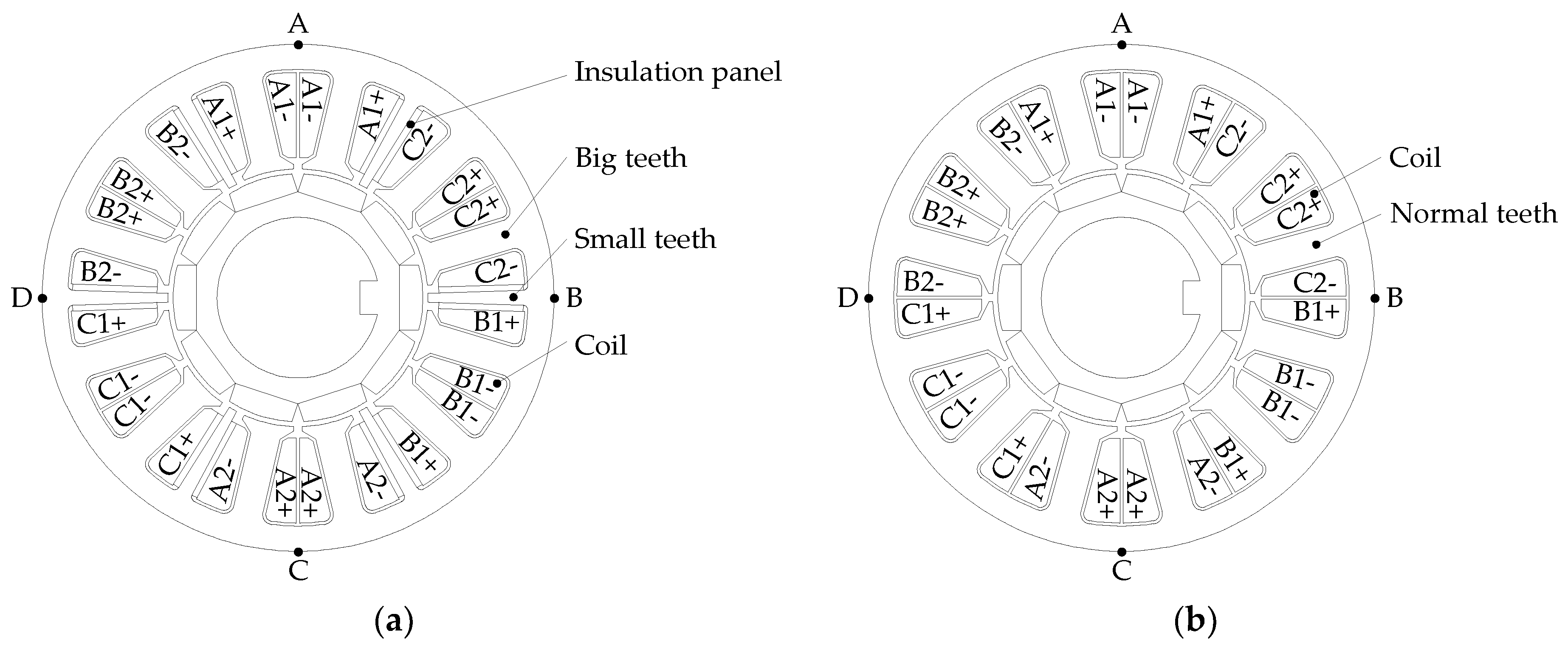
10]. In this paper, a dual-redundancy permanent magnet synchronous motor (DRPMSM) with no electromagnetic coupling and low heat coupling between phase windings was evolved from PMSM of 12-slot/10-pole (12s10p). By adding six small teeth in the common slot center of the two adjacent phase windings, the leakage inductance between the different phase windings was basically eliminated and the thermal coupling between the phase windings was reduced by means of appending the heat insulation plate on both sides of the small teeth [
11,
12,
13]. Two sets of three-phase symmetrical windings with star connection and the same phase of electromotive force were arranged on the DRPMSM. Under normal conditions, both of them work at the same time in double redundancy. When one of the three-phase windings malfunctions, its power supply is stopped and another normal three-phase winding continues to work.
The application of DRPMSM as the drive in the military field requires low vibration. Electromagnetic vibration is a main source of motor vibration and scholars worldwide have studied it in depth. Considering the influence of permanent magnet shape on motor vibration, by optimizing the shape of the permanent magnet, the amplitude of motor vibration can be reduced [
14]. In reference [
15], the finite element model was used to analyze the effect of stator teeth, slot wedge, and armature winding on the natural frequency of the stator. For the special purpose of PMSM in the operation of variable frequency, the amplitude of vibration can be reduced by eliminating the radial electromagnetic force of specific frequencies [
16]. Resonance occurs when the radial electromagnetic force is consistent with the modal frequency of the stator and will lead to great vibration and noise [
17]. It is interesting to note that the vibration affecting permanent magnets on the motor is higher than the rated load in PMSM [
18]. It has been recognized in [
18,
19,
20,
21,
22,
23,
24] that the vibration and noise of a motor can be reduced by changing the pole-slot match to raise the minimum mode of the radial electromagnetic force.
The different parameters affecting the vibration of the motor have been studied in depth through the method of theoretical derivation [
14,
15,
16,
17,
18,
19,
20,
21,
22,
23,
24] and are also demonstrated in
Section 3 but with more details on a different object. On the basis of the abovementioned research, the radial electromagnetic force on the yoke equivalent to the superposition of different order force waves and the influence of extra small teeth on vibration in DRPMSM are analyzed in this paper.
4. The Influence of Small Teeth on Radial Electromagnetic Force
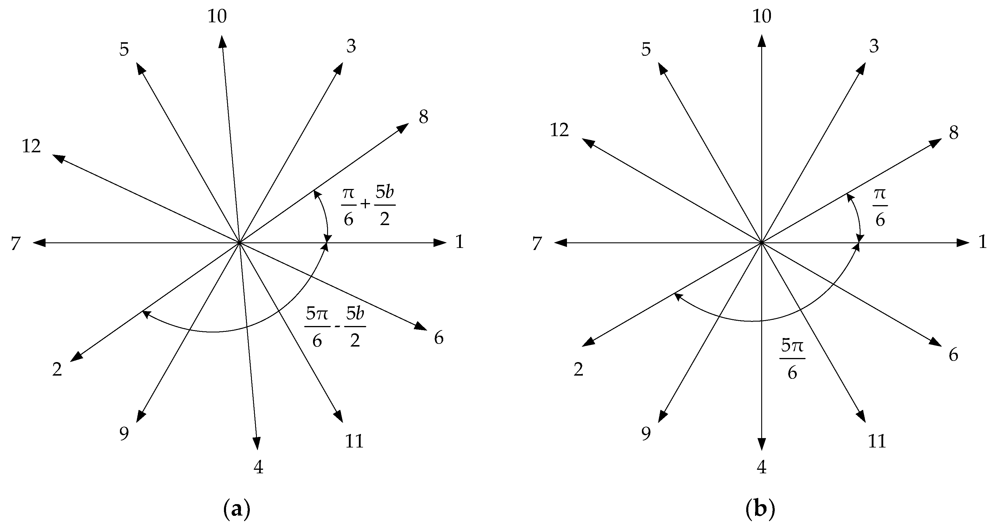
The simplified slot diagram of the stator in 12s10p is shown in
Figure 5, where
,
,
,
,
,
,
,
,
,
.
Assuming that the amplitude of radial electromagnetic force on the stator teeth surface is identical, the
lth-order radial force in air gap
is described as
where the amplitude of the
lth-order radial electromagnetic force in the air gap is
, and its frequency times of the
lth-order radial force is
.
Because the stator silicon-steel was rigid, the radial electromagnetic force on the stator teeth was calculated by the average value as
where the average value of the
order radial electromagnetic force on teeth number
(in
Figure 5) is
(unit: N/m
2) and
(unit: rad) is its angular position.
The average teeth forces are given by
where
,
,
,
.
The amplitudes of the average force on the stator teeth in four cases are shown in
Table 8.
The radial electromagnetic force on the stator teeth is transmitted to the stator yoke through the stator teeth. The amplitude of the radial electromagnetic force on the stator yoke with teeth is unequal to 0 and equal to 0 on the stator yoke without teeth, so the radial electromagnetic force acting on the stator yoke is periodic, continuous, and bounded during the period and conforms to the condition of Fourier expansion.
It can be equivalent to the superposition of different order force waves applied on the inner surface of the stator yoke.
is described as
where the ratio of stator teeth width to stator tip width is
, and its value is variable for the different stator teeth.
is the
order Fourier expansion coefficient of the
.
is the amplitude of
, so
is the amplitude of the radial electromagnetic force on the inner surface of the stator yoke.
can be obtained by
The relation between the mode number and amplitude of deformation for
can be expressed as [
21]
where
is the amplitude of the deformation caused by mode
of the radial electromagnetic force on the stator yoke,
is the coefficient determined by dimensions and structural properties of the stator, and
is the amplitude of mode
in radial electromagnetic force density distribution.
In fact, this basic formula cannot be used for accurate calculation and a detailed finite element structural analysis is needed. However, for a rough comparison, it is beneficial to use Equation (22) to study the resultant amplitude of the deformation caused by the radial electromagnetic force. When is constant, as shown in Equation (22), decreases with .
In this paper, is considered to be equal to and is considered to be equal to .
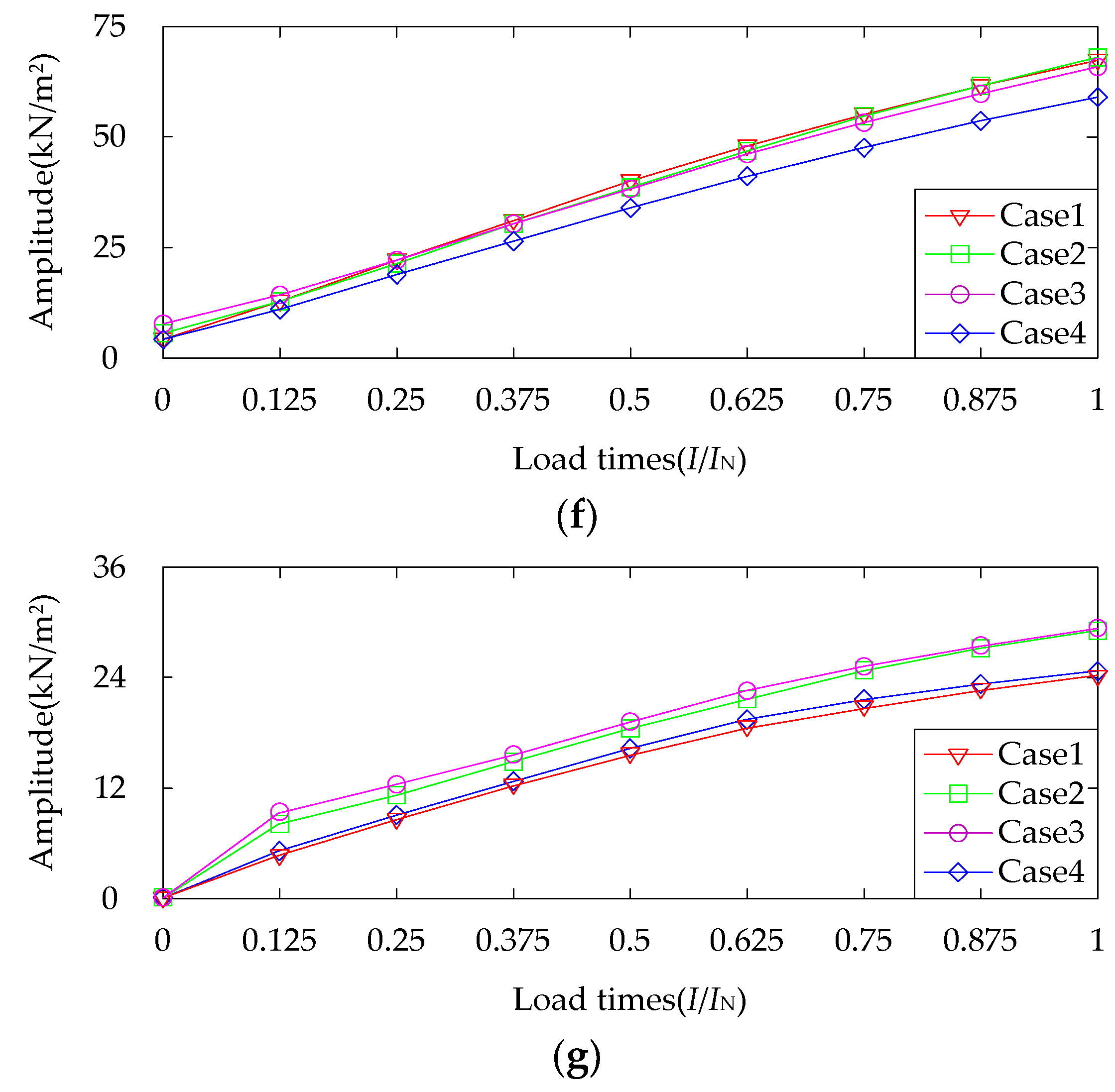
According to Equations (14)–(22), the Fourier expansion of radial electromagnetic force on the inner surface of stator yoke with different widths can be obtained, as shown in
Table 9.
In
Table 9, with the same structure of the stator, small teeth (yes) stands for the radial electromagnetic force acting on big teeth and small teeth together, and small teeth (no) stands for that on big teeth alone.
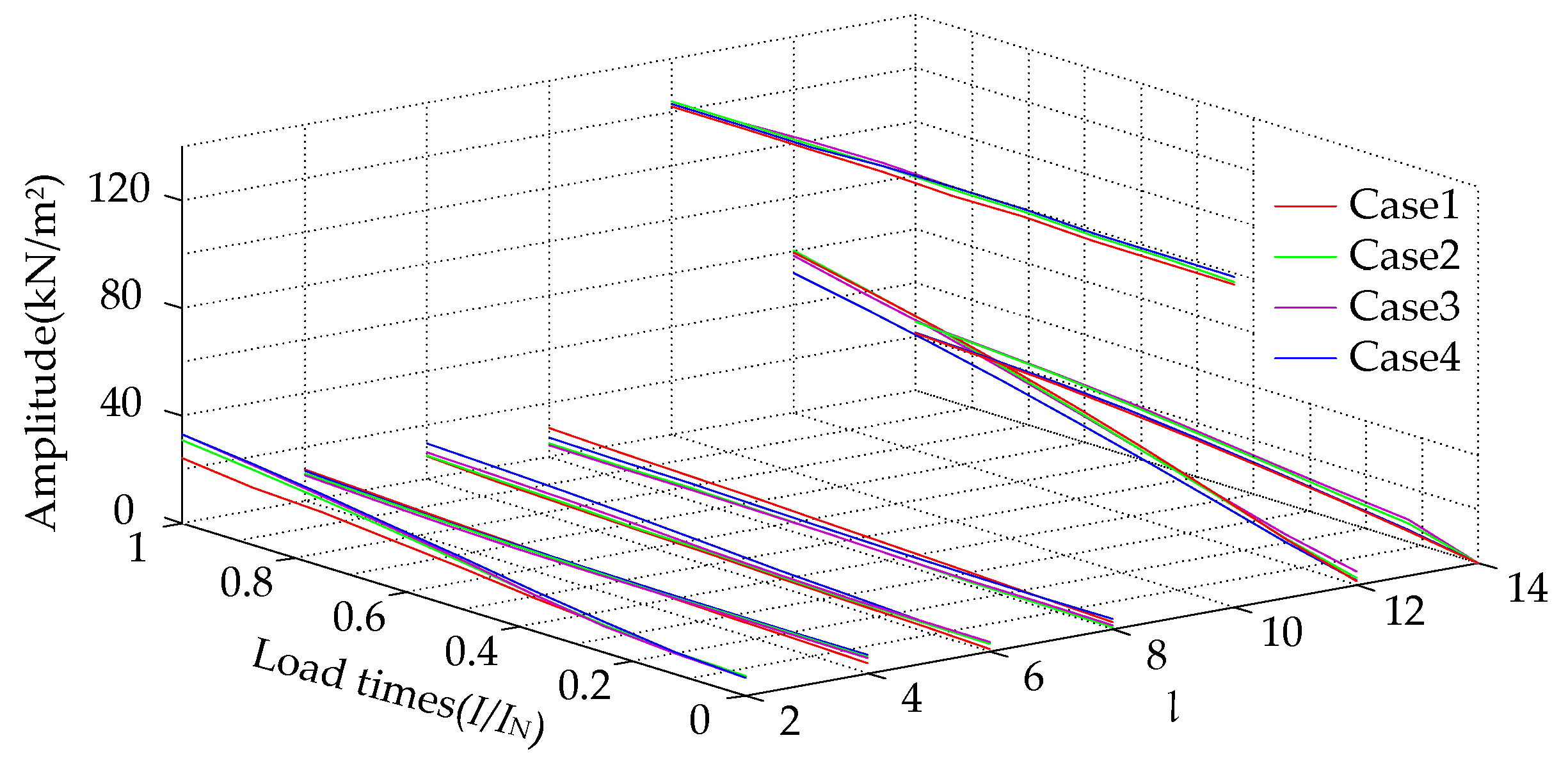
Table 9 shows that, for the radial electromagnetic force on the stator yoke
, when the order
l is equal to 2, 10, 14, the amplitude of
obtained by Fourier expansion is higher, so the amplitude of the
order radial electromagnetic force on the inner surface of the stator yoke is higher. When the order
l is equal to 4, 8, the amplitude of
is higher, so the amplitude of the
order radial electromagnetic force on the inner surface of the stator yoke is higher. When the order
l is equal to 6, 12, the amplitude of
is higher, so the amplitude of the
order radial electromagnetic force on the inner surface of the stator yoke is higher. According to
Figure 3 and
Figure 4 and
Table 9, the amplitude of
(
l = 2, 10) is much bigger than that of
(
l = 4, 6, 8, 12, 14),
(
l = 2, 4, 6, 8, 10, 12, 14), and
(
l = 2, 4, 6, 8, 10, 12, 14), so
(
l = 2, 10) can be considered only below.
For
, the amplitude of
(
l = 2, 10) increases with the small teeth width increasing on condition that the radial electromagnetic force on the big teeth only work. When
l = 2, the radial electromagnetic force on the small teeth raises the amplitude of
, and the larger the small teeth width, the larger the amplitude of
, so the amplitude in
increases. When
l = 10, the radial electromagnetic force on the small teeth decreases the amplitude of
, and the larger the small teeth width, the smaller the amplitude of
, so the amplitude in
decreases. For
(
l = 2, 10), its excited radial electromagnetic force frequencies are mainly 2
f (600 Hz), as shown in
Table 3,
Table 4 and
Table 5.
5. Influence of Small Teeth on Electromagnetic Vibration
5.1. Modal Analysis of Stator
It was important that the modal analysis of the stator structure is completed. This determined whether the resonance occurred on the stator when the frequencies of the radial harmonic components of electromagnetic force coincided with the modal frequencies of the stator.
The motion differential equation determined by the state vector method as follows [
24]:
where
is the mass matrices,
is the damping matrices,
is the stiffness matrices,
is the displacement vector, and
is the radial electromagnetic force vector.
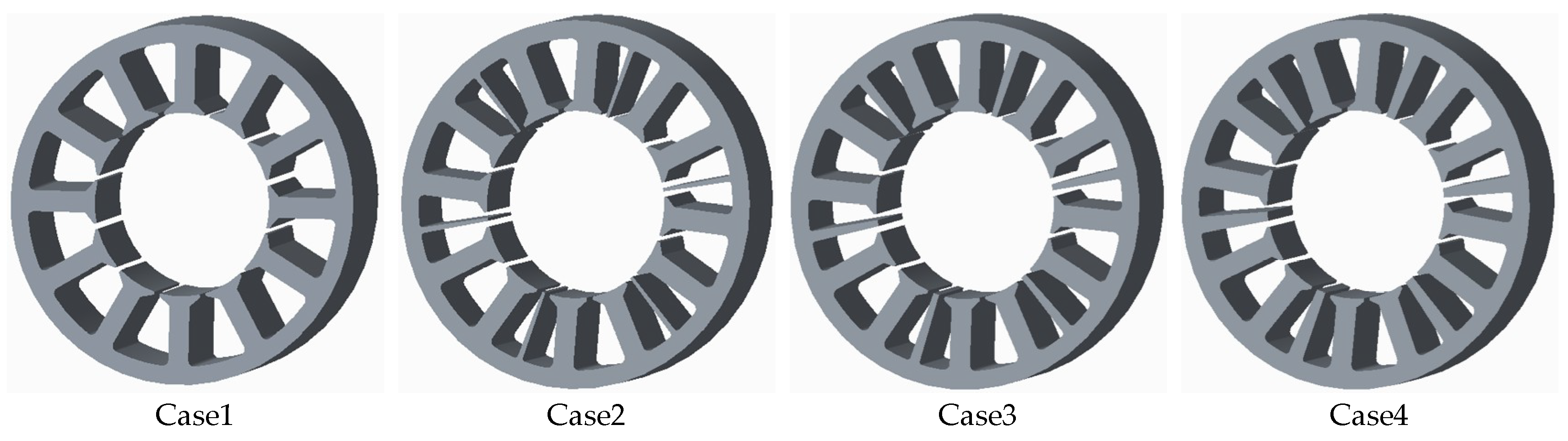
Because of the shell, the armature windings and rigid support affected the natural frequency of the mode. Thus, only the stator was considered, and it was assumed that the stator was completely unconstrained. The models of the three-dimensional stators of PMSM in different cases are shown in
Figure 6.
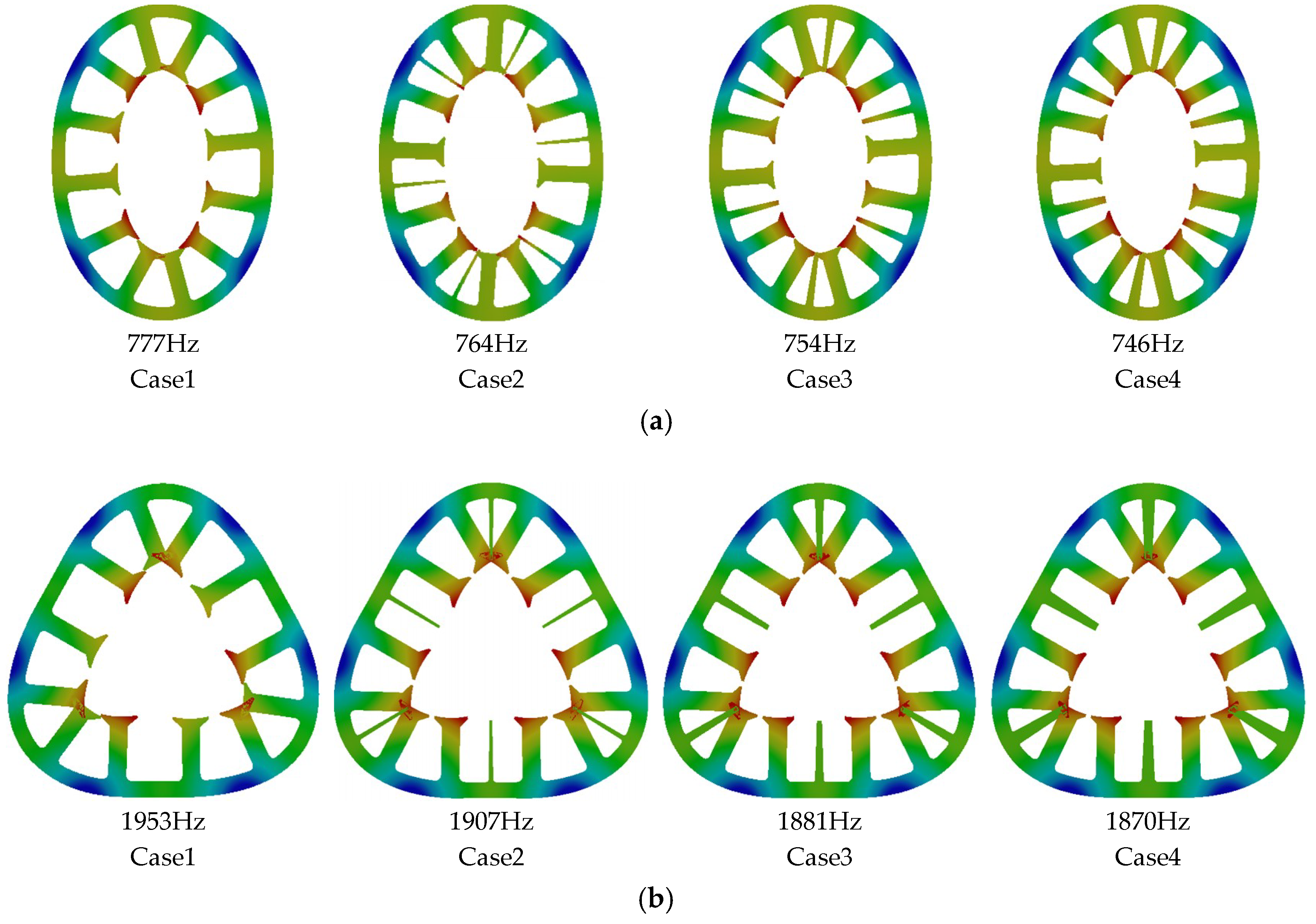
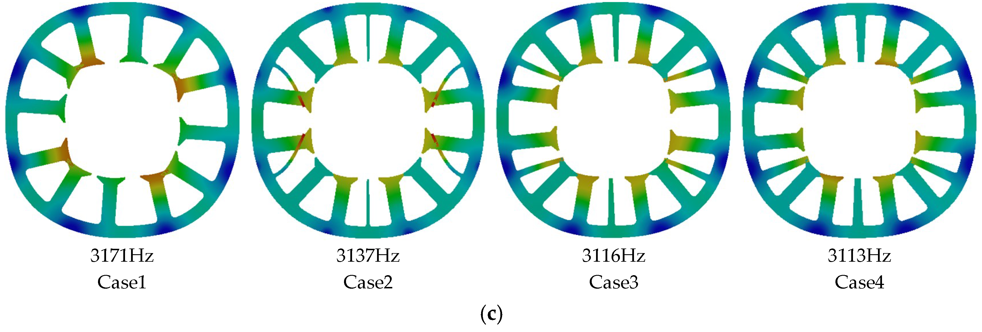
The material of the stator was DW310-35, its stacking coefficient was 0.95, and its length was 142 mm. The mode of the stator in 12s10p and its resonant frequencies of the 2nd and 4th orders were obtained by modal simulation, as shown in
Figure 7.
Compared with the resonant frequencies of the different small teeth width in
Figure 7, it was found that the resonant frequencies of the same mode order decreased weakly in Cases 1–4, and the small teeth had a weak effect on the resonant frequencies in the same mode shapes.
5.2. Vibration Analysis of Stator
The radial electromagnetic force on the stator teeth was coupled to the model of the stator by the finite element simulation of the magnetic field, and the vibration simulation of the stator was analyzed when the stator was excited by a radial electromagnetic force at two times the rated frequency (2
f = 600 Hz). By observing the average value of vibration velocity on A, B, C, and D in
Figure 1 under different teeth widths and load times, the curve can be obtained, as shown in
Figure 8.
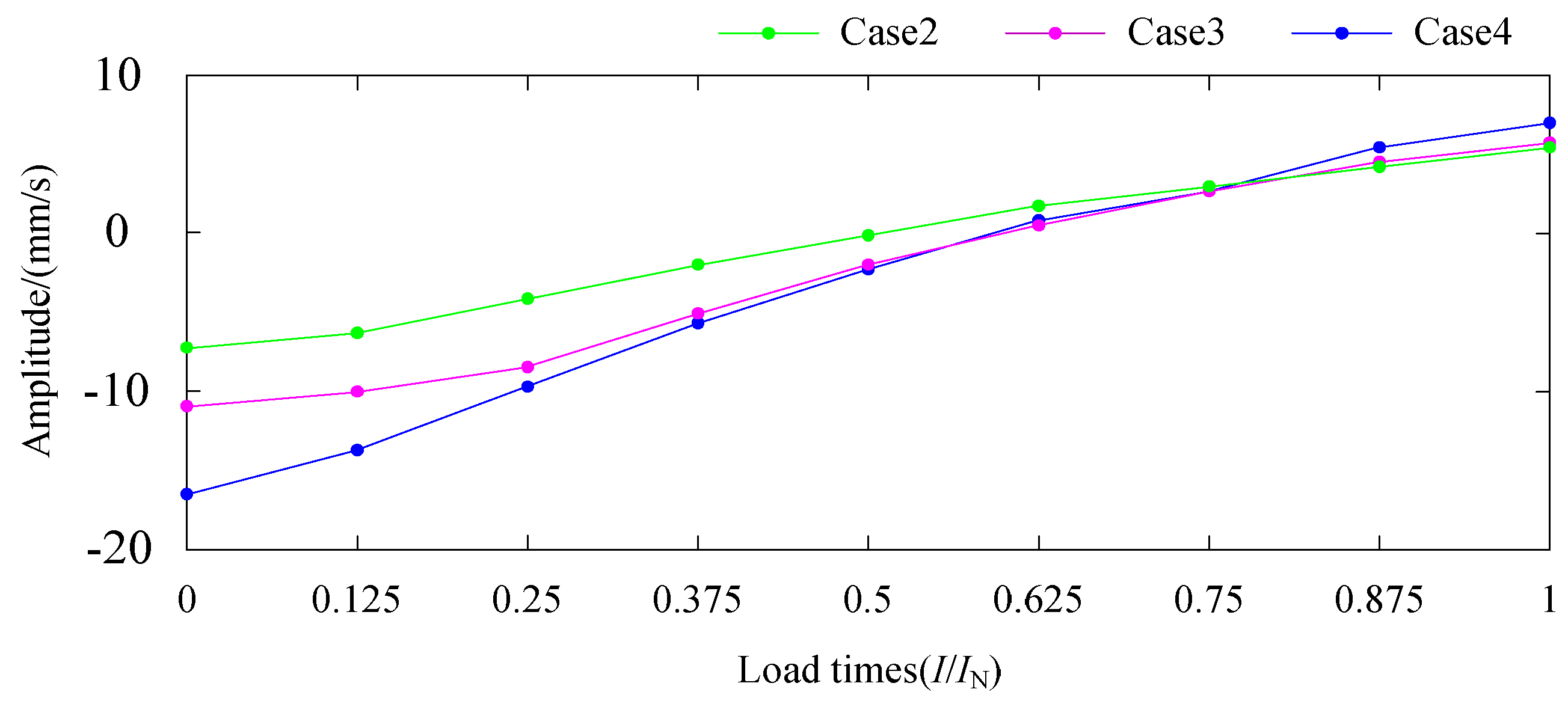
Four curves with the different colors are used to represent four cases of small teeth width. Solid lines are used to represent the radial electromagnetic force on big teeth alone and the discontinuous curves are used to represent the radial electromagnetic force on big and small teeth together. Comparing the curves of Cases 2–4 in
Figure 8, the velocity difference curve of stator vibration with load times can be obtained, as shown in
Figure 9.
Comparing the curves of the solid and discontinuous lines in
Figure 8 and
Figure 9, it can be found that with the larger width of the small teeth, the amplitude of vibration velocity caused by the radial electromagnetic force acting on big teeth alone increases and correspond to the increasing of
(
l = 2, 10) when the radial electromagnetic force on the big teeth work only.
When the load times are small, the amplitude of vibration velocity produced by the radial electromagnetic force acting on big and small teeth together is smaller than that on big teeth alone, and the larger the width of the small teeth, the larger the velocity difference.
When the load time is equal to 1, the amplitude of vibration velocity caused by the radial electromagnetic force acting on big and small teeth is bigger than that on big teeth alone, and the larger the width of the small teeth, the larger the velocity difference.
Under the light load, the amplitude of the 10th-order radial electromagnetic force of is much larger than the amplitude of the 2nd-order force of , so the radial electromagnetic force on the teeth is mainly of the 10th order. The radial electromagnetic force of on the small teeth reduces the amplitude of , and the larger the width of the teeth, the larger the reduction of vibration velocity.
With increasing load times, the amplitude of the 10th-order radial electromagnetic force on the teeth is almost constant, and the amplitude of the 2nd-order radial electromagnetic force gradually increases.
When the load time is nearly 1, the amplitude of the 2nd-order radial electromagnetic force of is bigger, so the amplitude of the vibration velocity produced by the radial electromagnetic force on the big and small teeth together is bigger than that on the big teeth only. The radial electromagnetic force of on the small teeth increases the amplitude of, and the larger the width of the teeth tip, the larger the increase of velocity.
As shown in
Figure 8, the amplitude of vibration is largest at the rated load when the load times is from 0 to 1. Hence, in order to ensure the low vibration of the motor overall, it is necessary to guarantee that at a rated load.


