1. Introduction
DC power distribution systems were first proposed for lighting purposes and were patented by Edison in 1883 [
1]. Due to limited advancements in DC technology, DC distribution systems were deemed inefficient and hence unsuitable for transmission of power over long distances. In 1886, Sprague proposed AC distribution systems [
2]. With the invention of transformers and induction machines, AC distribution systems could transmit power efficiently over long distances. As a result, they became popular and were universally adopted for electric power distribution. The advent of the semiconductor industry in the 1960s led to the introduction of power electronic converters (PECs) that were capable of improving the performance of DC distribution systems. With everyday advancements in semiconductor technology, PECs are becoming more efficient, reliable, cheaper, and smaller in size. With the help of PECs, DC distribution systems are now becoming more beneficial than AC distribution systems in terms of efficiency, reliability, cost, size, etc. [
3,
4]. In references [
5,
6,
7,
8,
9,
10,
11,
12,
13], the authors propose new topologies of PECs with high efficiencies and power densities that can be used to improve the overall efficiency of a DC distribution system.
A DC distribution system has many advantages over an AC distribution system. It offers higher efficiency and reliability at an improved power quality. It has reduced installation costs as it requires fewer power conversion stages, less copper, and smaller floor space. DC distribution enables simpler integration of renewable energy sources and energy storage systems. Since the power is distributed in DC, there is no reactive power or skin effect in the system. Unlike the AC distribution system, a DC distribution system facilitates plug and play features as it does not require any synchronization. Telecommunication systems and data centers are among the few surviving examples of DC distribution systems. They are low voltage (48 Vdc) power systems that have characteristics similar to a conventional DC distribution system. The requirement of DC power for major consumer electronic loads and recent developments in renewable energy technology as well as increased penetration of distributed energy resources have prompted renewed interest in DC distribution systems among researchers and industry players.
Ideally, a power delivery architecture should maximize system efficiency and provide power at a low cost. It should also be able to reliably supply power to critical and sensitive loads such as data centers, as these applications require uninterrupted power supply. Moreover, there should be room for further expansion as and when necessary. In this paper, different DC distribution system architectures are discussed and a comparative study is presented. The authors of references [
3,
4], and references [
14,
15,
16,
17,
18,
19,
20,
21,
22] show different power delivery architectures used for both AC and DC systems for different voltage levels. The optimum DC bus voltage level selection is done to maximize system efficiency, reliability, and flexibility of the system for future expansion while reducing system costs. Until the last decade most telecommunication and data centers were operating at 48 Vdc, as it is within the safe extra low voltage limits of the European Telecom standards EN41003 and UL 1950 to avoid hazards [
20,
21]. Recently, there has been a trend towards moving to higher DC bus voltages to reduce system costs and losses. However, there are challenges involved with higher DC bus voltages like safety and protection that can lead to fire hazards. Furthermore, the reliability of the system is also affected, as there is an increased risk of component failure involved with increased voltage and current stresses. This paper discusses the DC bus voltage level selection based on different safety standards and investigates the different aspects of DC systems in terms of system reliability and efficiency, ease of integration of renewable energy and energy storage systems, and availability of protection equipment and components.
In this paper,
Section 2 gives a brief overview of different power distribution architectures and DC bus structures for DC distribution systems at different voltage levels.
Section 3 discusses the efficiency improvement in DC systems. The safety, grounding, and protection aspects of DC systems are discussed in
Section 4.
Section 5 and
Section 6 discuss the reliability and cost of DC distribution systems. The DC bus voltage level selection is discussed in
Section 7 and
Section 8 gives insight into the current global market for DC distribution system in terms of facilities deployed, standards established, components available, and market penetration. Finally, conclusions on DC distribution systems are provided in
Section 9.
2. DC Distribution—Bus Structures and Power Architectures
2.1. DC Bus Structures
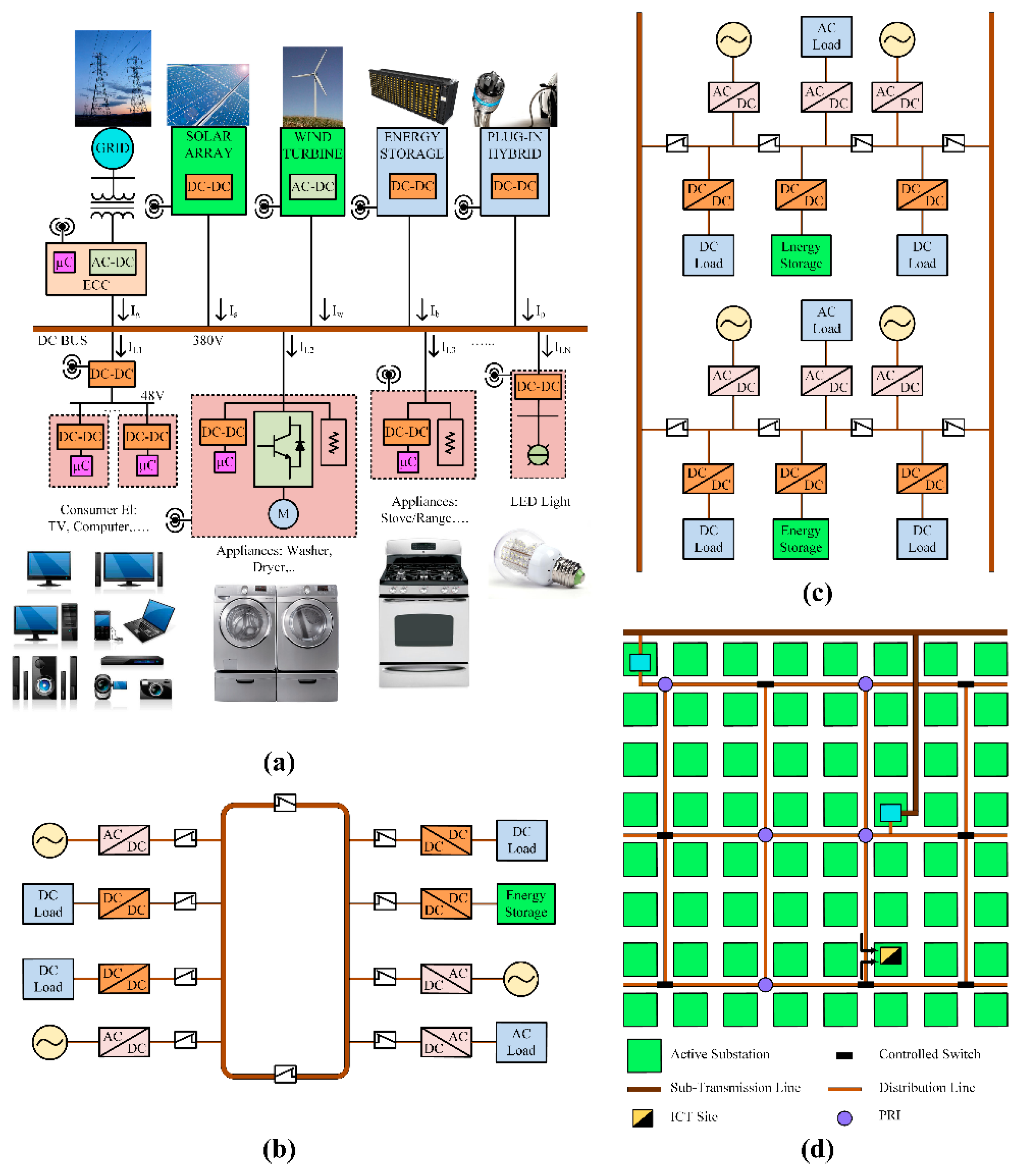
A DC distribution system can be considered a DC bus connected to various sources (AC grid, renewables, and energy storage systems) and loads (electronics, lighting, variable speed drives, etc.); typically, AC grid being the main source of supply. Four different DC bus structures are described in this section. Reliability and cost are the main factors considered in determining the bus structure for a distribution application.
2.1.1. Radial Bus Structure
This type of distribution structure is the most simple and economical in terms of implementation. The DC bus runs from one end to another with the sources and loads connected anywhere depending on their location, as shown in
Figure 1a. The reliability of the system is the least compared to other bus structures as a fault on the DC bus will result in the shutdown of the entire system.
2.1.2. Ring Bus Structure
As the name suggests, in this configuration the DC bus is in the form of a ring. This bus structure is more expensive than the radial one as it involves more copper. It also has improved reliability at increased cost. As seen in
Figure 1b, the DC bus is divided into two sections using switchgear. Thus, when there is a fault on the DC bus, the switchgear can be used to isolate the faulted DC bus from the un-faulted DC bus, thereby ensuring continuity in operation on the segment of the system with no fault.
2.1.3. Ladder Bus Structure
In this structure, the DC bus in the shape of a ladder increases the reliability of the system with an increase in cost compared to the ring bus structure. Ladder bus structure is an extension of the ring structure with higher reliability. As seen in
Figure 1c, when a fault occurs at any point in the system, the faulted region of the bus can be isolated from the rest of the system using appropriate switchgear.
2.1.4. Meshed Bus Structure
The meshed bus structure shown in
Figure 1d is a modified ring bus structure obtained when multiple ring structures are joined together. A system with meshed bus structure has the highest reliability compared to the other three structures. Obviously, this structure is the most expensive of all as it requires more copper.
It is observed that the higher the reliability requirement, the higher the cost of the system will be. Therefore, the selection of the bus structure is based on how reliable the system must be and how much one is willing to pay for it. For residential applications, where reliability is not a dictating factor, a simple radial bus structure can be implemented. One good example of a radial DC bus structure is the DC nanogrid architecture [
16], where the renewable energy sources and storage systems are integrated along with the existing power grid. If an application demands even higher reliability, one can choose from ring, ladder, or meshed bus structures depending on the budget and level of desired reliability. Highly reliable ring, ladder or meshed structures can be seen in telecommunication systems and data centers. A comparison of the advantages and disadvantages of the four DC bus structures discussed in terms of reliability, number of components, and cost is presented in
Table 1.
2.2. Power Architectures
In general, power architectures for a DC power system can be classified into centralized and distributed architectures [
21,
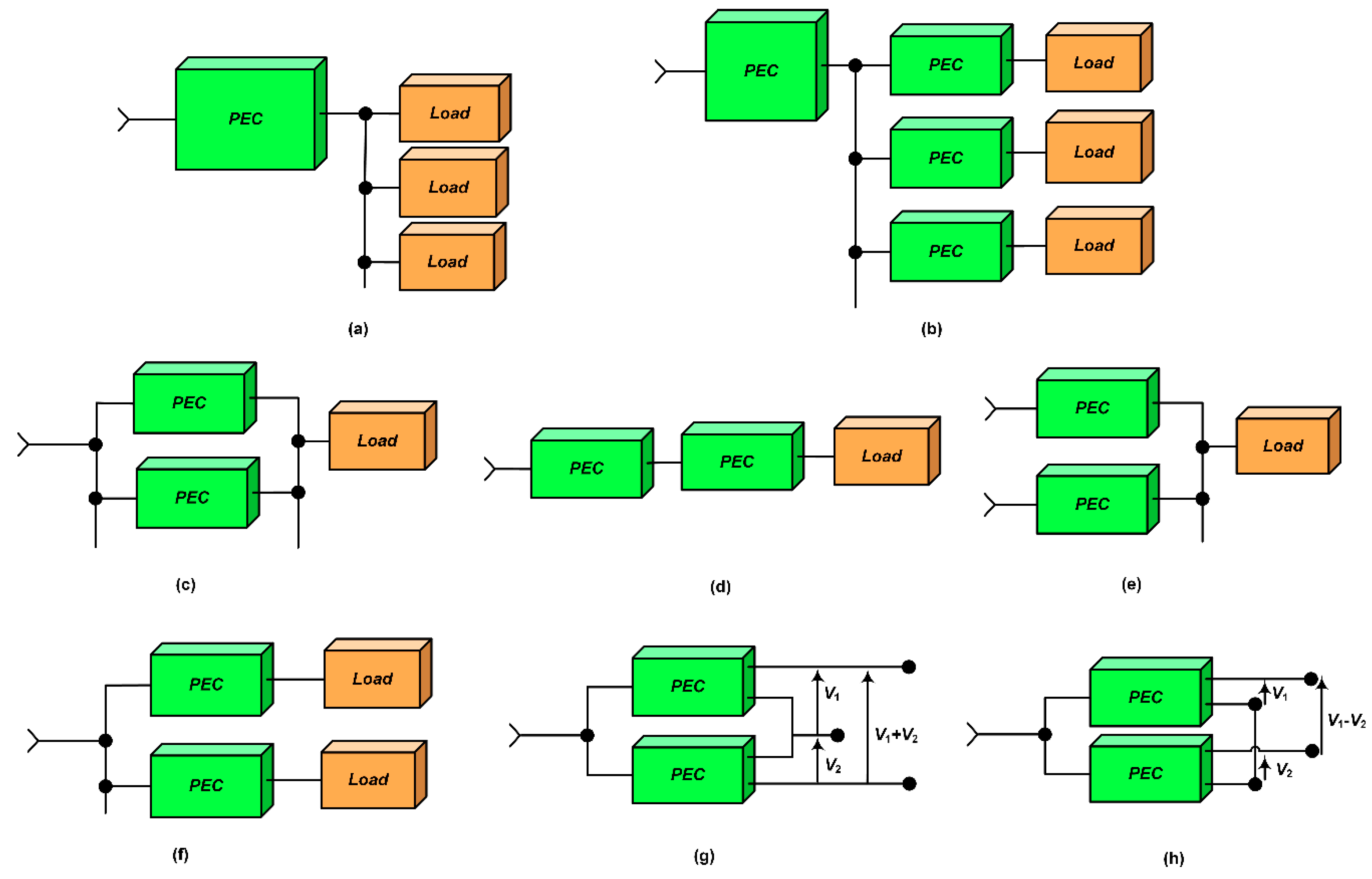
22]. The first DC power system introduced was a centralized architecture. In this system architecture, the power was generated, processed, and controlled in one centralized unit and delivered to loads through a network of power conductors or cables. The simple block diagram representation of a centralized power system architecture is shown in
Figure 2a. This type of system architecture is effective if the loads are all of a defined voltage level. As time progressed, the number of loads with different voltage levels increased on the system and eventually, the centralized power architecture could no longer support the needs of the loads. As a result, distributed power system architecture was developed that powered the loads through a number of PECs as shown in
Figure 2b.
Distributed power system architecture comprises of different PECs, which provide different voltage level outputs catering power to various loads. With ever increasing power demand and loads at different voltage levels, distributed power system architecture gained acceptance, globally replacing the centralized power system architecture. By using smaller PECs, this architecture enables the use of standardized low power modules that make it easy to customize an existing system for any special requirements in the future. PECs can be made more efficient with increased power density by operating at high frequencies, as they are required to handle low power. Higher reliability can be achieved by isolating a fault on one module and keeping the rest of the system unaffected. The various merits of distributed power architecture can be attributed to five basic configurations that are used in order to supply specific loads. They are as follows:
2.2.1. Paralleling
In a paralleling configuration shown in
Figure 2c, instead of using a single high power module, multiple low power PEC modules are connected in parallel to supply the load. Since a module processes part of the power, it experiences reduced thermal and electrical stresses, making the overall system more reliable even on increased component count. Individual modules can be reduced in size, cost, and made with a higher power density by operating at higher frequencies. This configuration provides simple maintenance and high reliability using redundancy (using ‘n+1’ modules instead of required ‘n’ modules).
2.2.2. Cascading
In a cascaded configuration shown in
Figure 2d, an intermediate bus is introduced into the power conversion of high voltage to a low voltage, which reduces power transformation losses. Also, distribution efficiency is improved when the converter is placed close to the load. The intermediate bus can be used for energy storage integration, improving the reliability and power quality. Cascaded units can be used for different purposes that are difficult to supply by a single converter. An example of such a cascaded configuration is a rectifier cascaded with a DC–DC converter where the rectifier can be used to achieve unity power factor and the DC–DC converter can be utilized for load voltage regulation.
2.2.3. Source Splitting
Source splitting configuration as shown in
Figure 2e, enables the use of multiple sources to supply one load. The power redundancy and simple battery backup feature improves the power quality and reliability of this system.
2.2.4. Load Splitting
In load splitting configuration, as shown in
Figure 2f, loads are supplied using multiple PECs. This configuration provides better load regulation, which can be difficult to achieve using a single centralized PEC because of the bus impedance. Moreover, this configuration allows selective battery backup for critical loads, which reduces the size and cost of batteries used in the system. Also, as different loads are supplied from separate sources, noise interference is reduced.
2.2.5. Stacking
Stacking configuration of PECs is mainly used to achieve desired output voltage levels by combining the outputs of multiple units. By stacking standardized units, non-standardized outputs can be obtained. For high voltage loads, the outputs of different PECs can be added as shown in
Figure 2g. When a smaller voltage than standardized voltage is required, the difference of outputs can be obtained by connecting the outputs as shown in
Figure 2h.
3. Efficiency
Efficiency improvement achieved using DC distribution systems compared to AC distribution systems can be attributed to various reasons. The main reason for higher efficiency of DC systems is it requires lower number of power conversion stages. In current architectures, the majority of residential and commercial loads comprise of electronic loads that require DC power. To supply these loads using a conventional AC distribution system, a power electronic converter is required to first convert AC to DC. This power conversion from AC to DC results in additional power losses, usually about 4–15% of the input power; assuming the converters are 85–96% efficient. Therefore, the total system losses become relatively high as the number of power converters increase. Applications using variable speed drives, a washing machine or heating, ventilation, and air conditioning (HVAC) systems for example, require a rectifier for AC to DC conversion and then another converter to generate variable AC. Having a DC system eliminates the use of the rectifier stage thereby improving the system efficiency.
The power conversion road map for AC and DC power systems given in
Table 2 [
23] shows that DC systems have fewer conversion stages compared to AC systems for DC loads, AC loads, and AC loads with AC converters (ACwC Load).
From another point of view, the absence of reactive power and skin effect are other reasons for improved efficiency in a DC distribution system compared to an AC distribution system. Since there is no reactive power in a DC system, the apparent and active powers are equal, which results in reduced losses in the system. In an AC system, skin effect increases the effective resistance of the wires and therefore results in higher distribution losses. Since such an effect is absent in a DC system, it has better efficiency than an AC system.
Various studies have been performed to validate the efficiency improvement in a DC distribution system. Lawrence Berkley national laboratory (LBNL) started investigating the DC distribution efficiency in data centers in 2004. The results obtained in their study stated that DC distribution consumed 28% less power compared to a typical AC distribution in data centers [
20,
24,
25]. In reference [
26], 220 Vac distribution was compared to 400 Vdc for power distribution in buildings. It was observed that in switching from AC to DC, an efficiency gain of 17.7%, 9.49%, and 18.9% was achieved in office, residential, and school buildings, respectively. The investigation carried out in [
25] concluded that at 50% load, 380 Vdc system was the most efficient among the systems considered for study. The results of this study are shown in
Table 3. The author of reference [
27] explains that when a distribution system integrated with DC sources (e.g., fuel cells, solar panels, etc.) was considered, a DC distribution system was more efficient than an AC system.
Low voltage DC systems designed for applications such as telecom and datacenters operate at 48 Vdc. At least three conversion stages from the AC input to the load are required to achieve this voltage level, which reduces the system efficiency. In references [
28,
29,
30,
31,
32,
33,
34,
35,
36], different voltage levels have been proposed for a DC bus based on efficiency, cost, and reliability considerations. In references [
3,
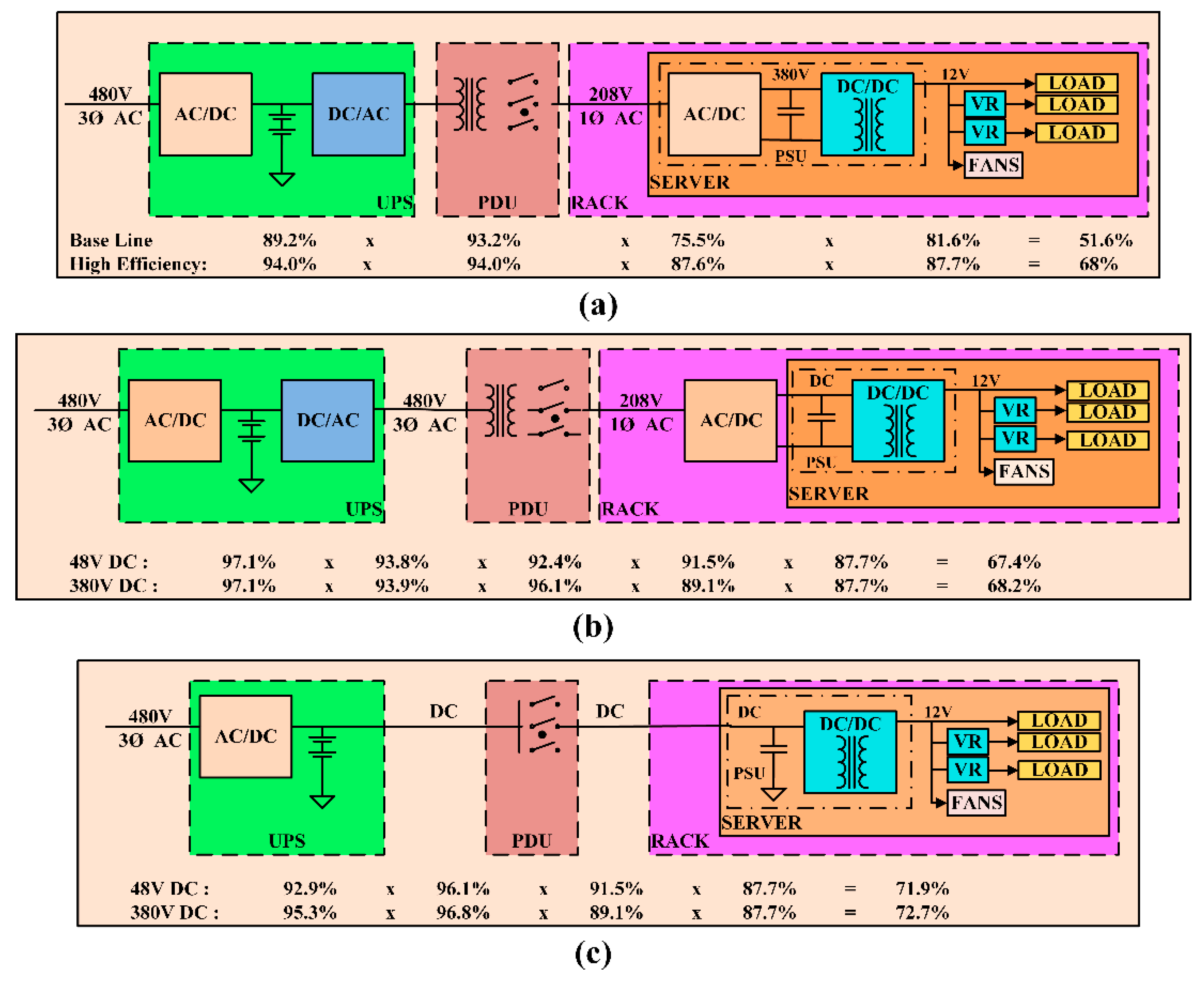
4], three different power architectures, namely conventional AC architecture, rack-level DC architecture, and facility-level DC architecture, have been described that are commonly utilized in data and telecom centers. Conventional AC system architecture for data center applications, shown in
Figure 3a, has several conversion stages that include the double conversion stage of the uninterruptible power supply (UPS). The AC input voltage is first converted to DC, where the energy storage system is connected, and then converted back to AC. In the next stage the voltage is stepped down to 208 Vac using a transformer in the power distribution unit (PDU). This AC voltage is once again converted to a DC voltage in the range of 380–400 Vdc using an AC–DC converter in the power supply unit (PSU). Isolated DC–DC converters are used to step down the voltage to levels suitable for distribution to the loads. For this configuration the overall system efficiency when operated at high load conditions is typically around 50%.
In the rack-level DC configuration presented in
Figure 3b, the AC–DC converter is shifted from the PSU of the server to the rack, thus reducing the server cooling requirements. The server volume is also reduced and the whole consolidated rack has higher power density and improved light load efficiency. Compared to the conventional AC architecture, an improvement in the overall system efficiency is not expected since the number of conversion stages are the same.
In the facility-level DC architecture shown in
Figure 3c, the DC–AC conversion stage in the UPS, the AC–DC conversion stage in the PSU of the server, and the transformer in the PDU are removed. Therefore, the number of conversion stages are reduced and the power delivery efficiency is significantly increased.
In reference [
36], a 380 Vdc modified power delivery architecture was proposed for server applications because it is more efficient than the conventional 48 Vdc system. In the modified power delivery architecture, the improvement in efficiency is obtained by reducing the number of power conversion stages and placing isolated DC–DC converters close to the load. Based on the abovementioned references and their claims, one can reach the conclusion that not only is a DC distribution system more efficient than a conventional AC system, but a higher voltage DC system also offers higher efficiency.
4. Safety and Protection
Two of the main concerns associated with DC distribution are the risk of electric shock and protecting equipment from damage that can also result in electric fires. The main reason behind this concern is that it is challenging to break a DC current compared to an AC current. Switchgear including circuit breakers, fuses, etc., and proper grounding methods are required to make the DC system safer. Comprehensive research has been conducted and papers have been published on improving the safety in DC distribution systems [
37,
38,
39,
40]; different papers have studied protection against electric shock related to DC generating devices such as photovoltaic generators from the perspective of personal safety [
41,
42]. Moreover, higher DC voltage levels would result in leakage currents in the system that can cause corrosion of the underground equipment, transformer saturation, and faulty operation of protective equipment [
43].
4.1. Personal Protection
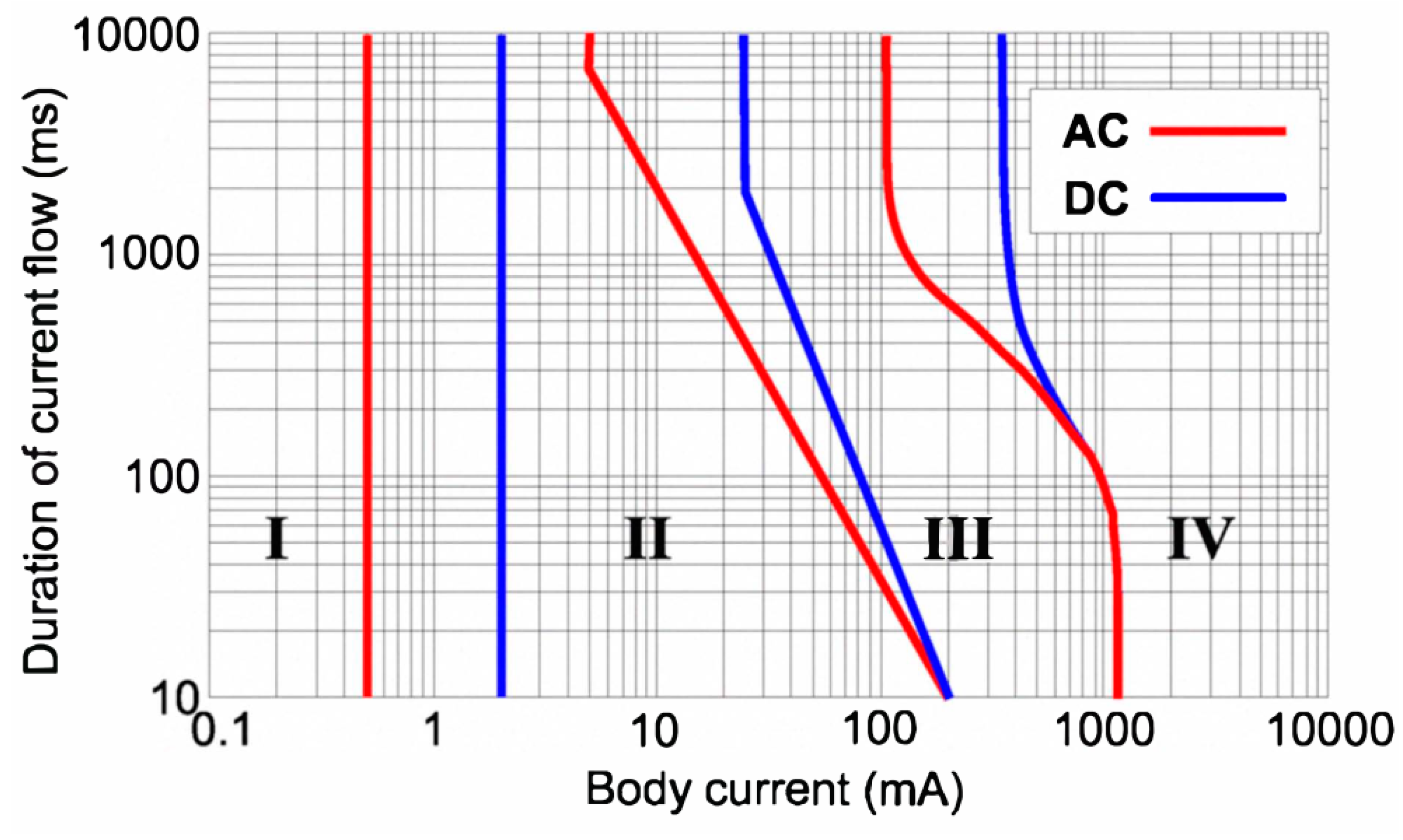
In order to evaluate personal protection and safety requirements of DC and AC systems, it is important to understand the effects of DC and AC currents on human body. The effect of an electric shock depends on the current magnitude, the duration of current, the current path, and the type of voltage (AC or DC). Among all the possible effects of electric shock, ventricular fibrillation is the most dangerous. Hence, in order to prevent any casualties proper protection needs to be provided. The authors of [
37,
39], provide a characteristic curve of body current (AC and DC) vs. the duration of current flow, which is shown in
Figure 4.
The graph is divided into four regions based on the effects on the human body:
No effect
A little pain but no dangerous effects
Muscular contraction and respiratory compromise, which are reversible
Critical effects such as ventricular fibrillation
It can be observed from the figure that the magnitude of safe operating current limit for DC is higher compared to AC, thus making DC safer to operate than AC.
4.2. Equipment Protection
Protective devices such as circuit breakers and fuses are similar for both the AC and DC systems. However, in the case of DC systems, they have to tolerate more stress while breaking the current due to the persistent nature of the arc. For residential applications and DC buildings, circuit breakers are commonly used instead of fuses as they can be reset when the fault is cleared. As the voltage and current ratings of the circuit breakers are lower for a DC system compared to an AC system, same components can be used for protection on both the AC and DC sides of a system. Furthermore, in the event of a short circuit, individual converters are usually equipped with short circuit protection and can easily detect a fault by observing the DC bus voltage. In such cases, when the DC bus voltage falls below a certain threshold, the controller can identify a short circuit and shut down the system. However, DC fault currents in some compact devices pose many challenges that demand advanced electrical protection requirements, therefore making the selection of suitable DC circuit breaker technology much more challenging [
44].
Many advantages of DC distribution systems are currently driving the market growth for DC technologies. Since equipment protection has been a major concern, many companies have been researching DC protection devices. Currently, major companies have started providing products used in DC distribution that follow existing standards for safety. Companies like ASEA Brown Boveri (ABB), Carling Technologies, Schneider, Nader, Siemens, etc., provide DC circuit breakers and fuses to be used for safety and protection purposes in DC distribution systems.
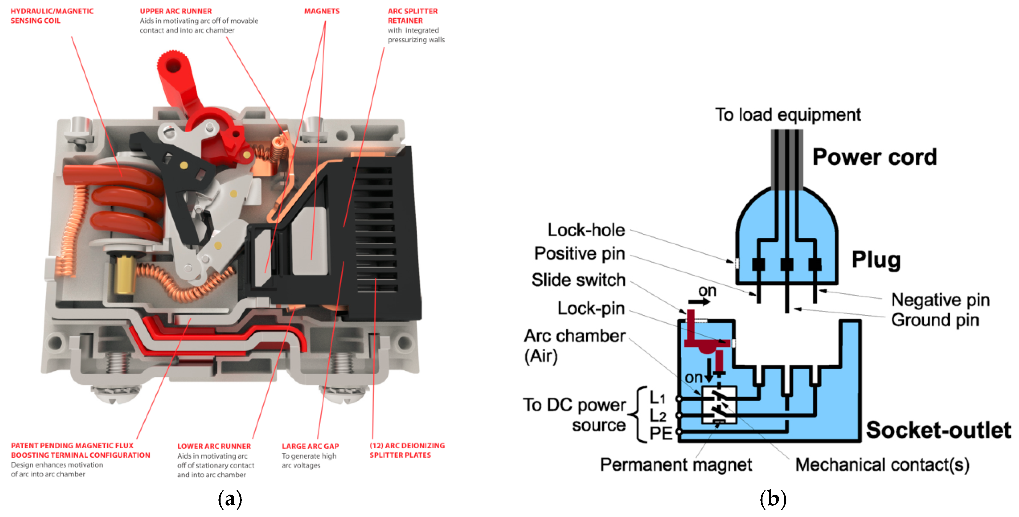
Figure 5a shows the design features of CX-series circuit breakers of Carling Technologies that is ideal for 380 Vdc applications [
45]. It uses a special arc-quenching method, enabling it to break high DC currents and handle high DC voltages.
DC distribution systems for commercial buildings and data centers require a distinctive plug and socket that should provide arc extinction as well as prevent electric shocks. These plugs are also equipped with mechanical locks to ensure human safety. The Nippon Telegraph and Telephone (NTT) Corporation and Fujitsu Component Limited have developed a 400 Vdc, 10 A plug and socket, as shown in
Figure 5b, which can be used for DC distribution system [
38]. When a DC current is interrupted, the resulting arc can damage the equipment. To prevent this, the plug should not be removed from the socket when the power supply is on. However, there can be instances during emergencies or when the plug is accidentally removed from the socket while the power is still on. During those cases, the plug and socket should be capable of taking care of the arc extinction and shock prevention tasks.
4.3. Grounding Methods
Grounding is a mandatory requirement in distribution systems as it provides personal safety and decreases the risk of fire hazards. Also, it reduces equipment damage, service interruptions during short circuit and earth faults. Other advantages of grounding include reduced radiation and conduction of electromagnetic emissions, providing tolerance to electrostatic discharge and lightning interference. Different grounding methods discussed in [
37,
39,
40] are as follows:
4.3.1. Direct Grounding Method
This type of grounding involves connecting one of the lines directly to the ground. There are three ways in which direct grounding can be implemented. They are listed below:
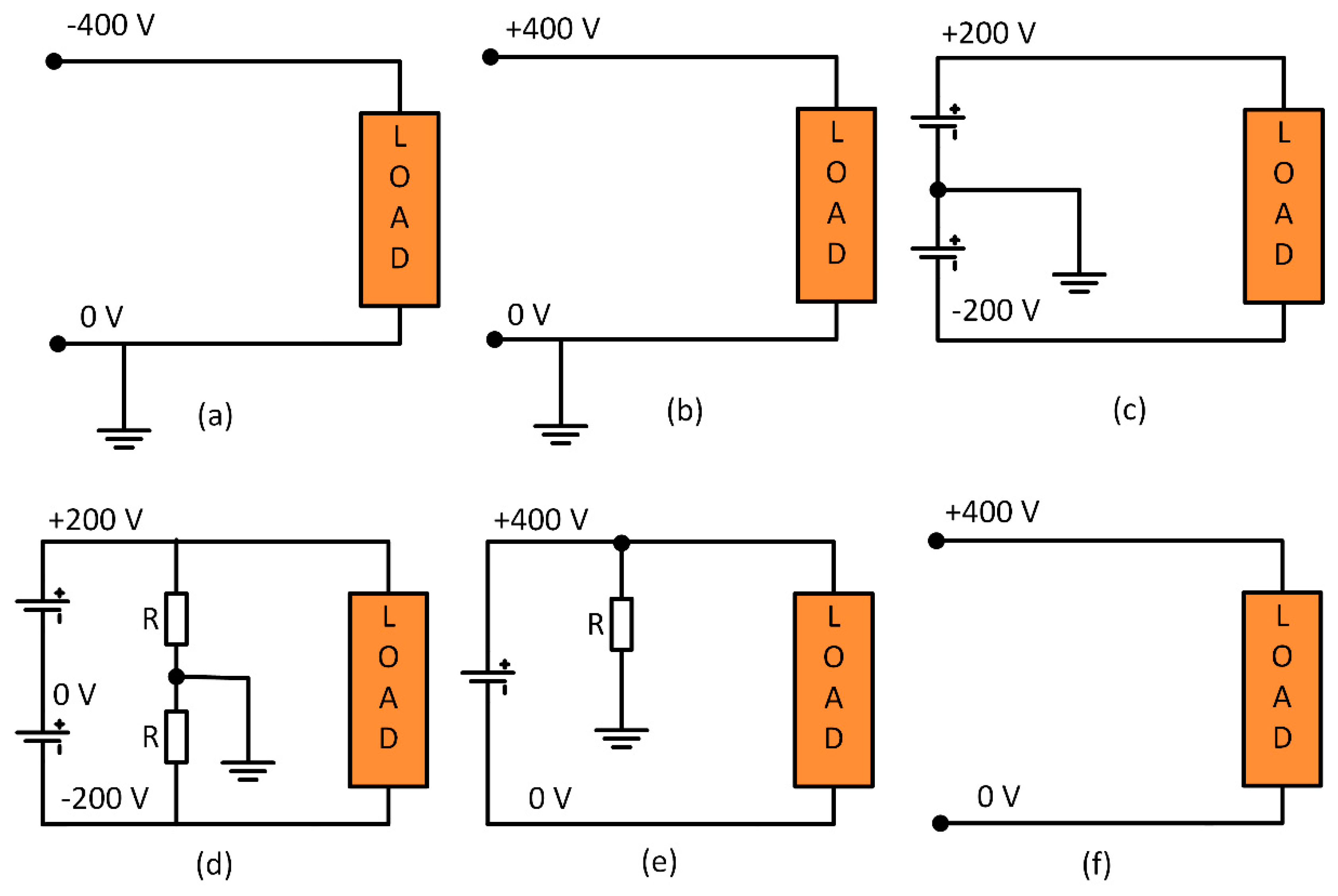
Positive line grounding: In this system, the positive line is connected to ground as shown in
Figure 6a. This system provides easy detection and breaking of current during a short circuit or earth fault. Monopole breaking is used to break the current. During a fault, the direction of the current through the human heart is upward and the heart-current factor F [
39] is twice that of the direct negative grounding system. As a result, it seems like twice the current is flowing through the human body. The current one receives during an electric shock in this type of grounding is the largest among all the grounding systems as the circuit impedance is very low. However, as the fault current is large, it can be interrupted with better accuracy.
Negative line grounding: In this type of grounding the negative line is connected to the ground as shown in
Figure 6b. The properties of this grounding method are similar to positive line grounding. The current one receives in this type of grounding is usually high, but not as high as positive line grounding.
Mid-point line grounding: In this type of grounding, the voltage to grounding is half of that compared to one end grounding as shown in
Figure 6c. It is easy to detect and break currents during short circuit and ground faults. The current is usually large when short circuit or earth faults occur on the negative line. When breaking fault current, it is necessary to break both the positive and negative lines at the same time. Usually, rectifiers and batteries implement this type of grounding and hence they need to deal with higher initial costs.
4.3.2. Mid-Point Grounding with High Resistance
Compared to a direct grounding system, this method makes protection against electric shock easier and the voltage to grounding is halved. Unlike in direct grounding, this method requires a resistance balancer in order to avoid any difference in ground voltage between positive and negative lines. Also, detecting an accidental current is difficult during faults as the magnitude of the current is small due to the high resistance. Hence, this method has decreased detection accuracy. Similar to mid-point line grounding, both the positive and negative lines have to be disconnected at the same time. In the mid-point high resistance grounding system, as the number of loads increases, the total resistance of the system decreases and the fault current is no longer small. A simple representation of this type of grounding is shown in
Figure 6d.
4.3.3. One-End Grounding with High Resistance
This method provides an even easier detection and breaking of fault currents compared to the direct grounding system. Monopole breaking of accidental current is possible as it is a one-end grounding method. However, detecting an accidental current is difficult since the magnitude is small and hence it has decreased detection accuracy. Just like in mid-point high-resistance grounding, the combined resistance decreases as the number of loads increase.
4.3.4. Floating System
In this type of grounding, there is no return path to ground and hence the current received during an electric shock is almost zero. This type of system is not very safe because just like in high-resistance grounding systems, the combined insulation resistance of the system decreases as the number of loads increase. Also, implementing such a system is very expensive as the devices used will require complete isolation. It is difficult to detect an earth fault and the voltage to ground may not be constant.
According to [
37], based on its merits; NTT Facilities, France Telecom, and Emerson network power have selected and highly recommend high resistance mid-point grounding for 400 Vdc distribution systems. This method provides better personal safety (by limiting fault currents to harmless levels) compared to other grounding methods for higher DC voltages.
5. Reliability
The reliability of both AC and DC systems depends on their system architecture and the level of redundancies. Especially, in DC systems, increasing the system voltage level adversely affects the electrical stresses experienced by the components (switches, breakers, etc.), thereby reducing the reliability of the system. Switching devices like power MOSFETs, IGBTs, diodes, etc. should always be operated within their safe operating area and, hence, are selected considering enough safety margins to take care of the voltage and current transients.
It has been observed that an increase in bus voltages reduces the life of capacitors [
46]. The lifetime of electrolytic capacitors is given by
In the above equation, L is the lifetime (hours), L0 is the base lifetime at maximum core temperature (hours), Tcore and Tcore_max are the normal and maximum operating temperatures of the core (°C) respectively, and Mv is the voltage multiplier, which is the ratio of rated voltage to the applied voltage. The life of the capacitors is adversely affected when they are subjected to higher voltage and current stresses, which causes their core temperature to rise, resulting in degradation of their performance. Therefore, it is very important to select suitable capacitors with sufficient voltage ratings. On the other hand, DC systems with higher DC bus voltages would require smaller capacitances because for the same amount of power the capacitance is inversely proportional to the square of voltage. Thus, the system reliability can be improved by selecting capacitors with sufficient voltage ratings and by also using a series-parallel combination of capacitors.
If batteries are used for energy storage in higher voltage DC systems, then more battery cells would be required to be connected in series to attain the required voltage. This leads to reduced system reliability as the failure in any one cell in the string of cells would result in the failure of the whole battery pack. This issue can be addressed by using high-efficiency, high-gain bidirectional power converters and having a reduced number of series battery cells, making the system more reliable.
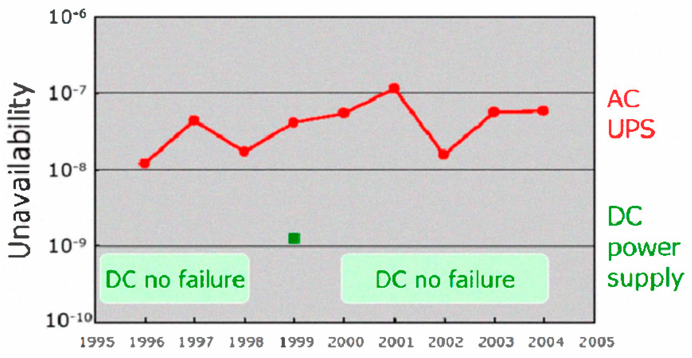
Figure 7 shows the field data collected by NTT facilities of Japan on AC UPS and DC power supplies [
47]. It can be seen from the plot that DC power supplies are less prone to failures compared to AC UPS systems. In [
48], a static reliability modeling approach was used to compare the reliability and availability of different AC UPS topologies and 380 Vdc topologies typically used in the telecom and data center applications. The reliability of a system can be calculated based on the MTBF (Mean Time between Failures) and MTTR (Mean Time to Repair) of the components, sub-systems, and other relevant events.
where,
A and
U are the availability and unavailability of the system, respectively, and
R(t) is the time-dependent reliability function. It has been shown that the reliability and availability of the DC UPS system is 10 times higher than that of the AC solution.
In telecom and data centers, DC distribution systems are more reliable than conventional AC systems despite the fact that the components experience higher electrical stresses [
49]. The reason behind this higher reliability is the reduction in the number of conversion stages used in these systems. The authors of [
24] mention that data centers with 380Vdc distribution are 1000% more reliable due to the elimination of the extra conversion stages. A study performed on applying 380 Vdc distribution to a 5MW data center of Intel JFSI module C in Hillsboro, found that the reliability of the system using 380 Vdc were higher compared to an AC tier IV distribution [
24].
6. Cost
DC distribution systems cost less than AC distribution systems. Using higher DC voltage levels further reduces the system costs and improves the system efficiency, thus reducing the operational costs of the system. Power electronic converters add up to being a major component of the system cost. The reduction in the number of conversion stages using a high voltage DC system eliminates the need for these converters, which greatly reduces the system costs [
50]. Moreover, smaller floor space is required as number of conversion stages are reduced, which further reduces the cost. On the other hand, higher voltages require elaborate protection schemes with costly fusing, wiring, and non-standard connectors that can offset the cost savings. Furthermore, the component costs can also add up to the overall system costs, for e.g., the system would now require expensive capacitors with higher voltage ratings. Thus, these design factors can cause some offset of the savings.
With an increase in voltage level, the amount of copper required to limit the copper losses decreases. This is inversely proportional to the square of the voltage. The authors in reference [
51] compare the copper cable required for a power transmission of 100 kW in 48 Vdc and 400 Vdc. They conclude that the 400 Vdc requires 10 times less copper than the 48 Vdc, making it less costly. Also, the cabling and installation costs are reduced as the smaller conductors used are more flexible and easier to lay.
According to reference [
24], a 380 Vdc system, compared to an AC system, requires 15% less initial capital cost due to the reduced power conversion and 33% less floor space, which contributes to the reduced cost; it also has a 36% lower lifetime cost. Conductor costs in distribution systems can be 10–15% of the total hardware cost and increasing the DC bus voltage level can represent less than 5% savings in the total hardware costs [
31]. In reference [
31], it has been shown that the cost of a 270 Vdc system is 15% lower than that of a 48 Vdc system. The cost breakdown for a 30 kW, 270 Vdc, and a 48 Vdc system is shown in
Figure 8. It is shown that, due to the lower number of conversion stages, the equipment cost is lower for the 270 Vdc system. The cabling cost is also lower compared to a 48 Vdc systems since smaller diameter wires are used. On the other hand, the battery cost is higher for a 270 Vdc system since more cells are connected in series.
7. Voltage Level Selection
The voltage level of DC distribution system should be selected to maximize the system efficiency and reliability, while reducing system costs and increasing the flexibility of the system for future expansion. The voltage drop and power loss [
52] in a DC line can be calculated using Equations (5) and (6). According to these equations, with line resistance and power requirement being constant, the only way to achieve a smaller voltage drop and power loss is by selecting a higher DC voltage for the distribution.
European telecom standard EN41003 and UL 1950 designated 60 Vdc as the maximum SELV (safety extra low voltage) limit [
20,
21]. For this reason, a nominal voltage of 48 Vdc has been chosen as the best choice for low-voltage distributed power system in conventional data centers and telecommunication systems. However, higher system voltages are preferred for the abovementioned factors, but there are also challenges like system safety and protection that can lead to fire hazards. Furthermore, the system reliability is affected as there is enhanced risk of component failure with the increased voltage and current stresses.
In reference [
30], it has been reported that Telecom New Zealand deployed a 220 Vdc system for increased power capacity to replace the existing 50 Vdc system. The installed system has reportedly reduced the installation and copper costs, uses 30–40% smaller batteries, and maximizes available floor space. In reference [
35], for a 220 Vac single-phase system or 380 Vac three-phase system, the DC bus voltage is chosen to be ±110 Vdc with mid-point grounding. The DC bus voltages are selected such that the existing electric appliances can be used in the proposed system with few or no modifications. In reference [
36], (DC)
2 ™ concept has been introduced for DC integrated data centers, which have higher system efficiency and reliability compared to conventional AC distribution systems. This concept involves enhancing the operational availability of the data centers with the backup provided by using different distributed energy sources and energy storage systems. The distribution bus voltage of the proposed system is in the range of 500–550 Vdc and has increased system reliability with the integration of the distributed energy sources. Furthermore, it has been reported that the improvement in the system efficiency decreases the power required for the cooling systems, which results in a 21% savings in total energy consumption compared to AC systems.
8. Global Market for DC Distribution Systems
The only existing DC distribution implementations, until the last decade, were telecommunication and data centers operating at −48 Vdc. Research initiatives on high-tech buildings like telecommunication and data centers began in the early 2000s as a result of energy issues in California. The LBNL started looking into the efficiency of power distribution in data centers in 2004. A 380 Vdc distribution system was set up for demonstration in Newark, CA. Later, in its 2008 report, it reported an improvement in efficiency of 28% and 7%, respectively, compared to 208 Vac and 408 Vac systems in data centers [
20,
24]. By 2009, new facilities with DC distribution were already being implemented and studied globally, with voltage levels varying between 220 Vdc to 550 Vdc. By the end of 2014, there were more facilities implementing DC distribution at a voltage level of 380 Vdc [
53,
54,
55,
56,
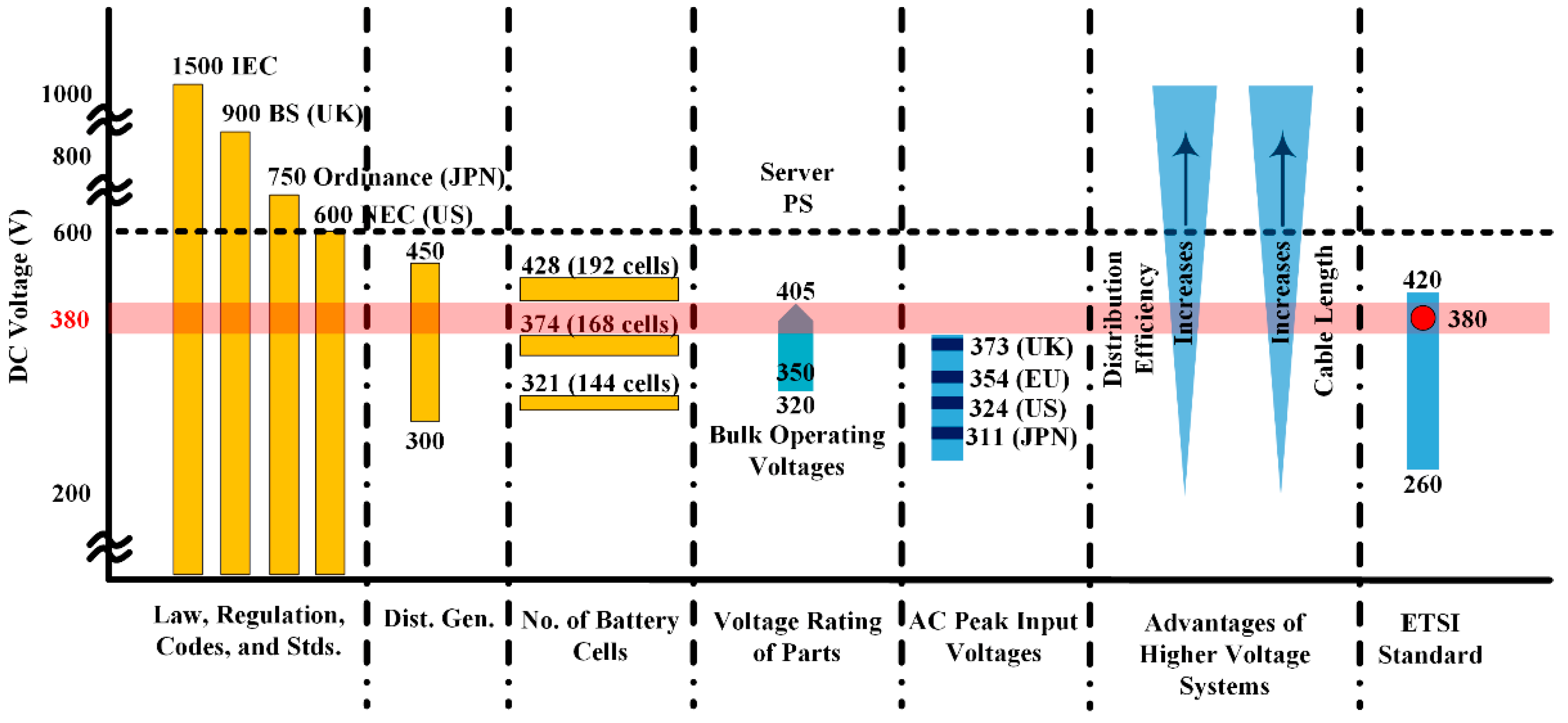
57]. As shown in
Figure 9, it can be observed that the telecom and data center industry is converging at 380 Vdc as the voltage level suitable for DC distribution [
47,
53,
54,
55,
56]. As of 2014, several facilities with high voltage DC systems have been established around the globe and are listed in
Table 4.
The growing number of demonstration sites and early adopters indicates a growing interest in 380 Vdc distribution. Many industry standard bodies like the European Telecommunications Standard Institute (ETSI), the Alliance for Telecommunications Industry Solutions (ATIS), the International Telecommunications Union (ITU), eMerge Alliance, the International Electrotechnical Commission (IEC), Underwriters Laboratories (UL), and many others have released standards and are currently working on more in 380 Vdc distribution [
53,
54,
55,
56]. The standards released by 2014 are listed in
Table 5. These standards are related to the power supply interface, DC UPS, DC equipment installation and grounding, safety, and component connectors. Currently, more research is underway on standardizing 380 Vdc distribution. Many companies have already released products compatible with 380/400 Vdc distribution into the market. A list of companies providing components for 380 Vdc distribution is given in
Table 6. Many more companies are showing interest in 380 Vdc and announcing products for the future.
9. Conclusions
DC distribution systems have many inherent advantages over AC distribution like improved efficiency and reliability, easier integration of renewable energy sources and energy storage systems, and reduced costs. Moreover, DC systems have no reactive power and frequency stabilization issues, which result in reduced copper losses. Many loads like consumer electronics, light-emitting diode (LED) lighting systems, appliances using variable speed motor drives, etc., require DC power. Currently, major applications of DC distribution systems are in the fields of telecommunication systems, data centers, DC buildings, and microgrids.
In the current scenario, new facilities are being deployed with DC distribution worldwide due to its many advantages. 380 Vdc is the accepted voltage level among all the organizations establishing facilities with DC distribution due to its high efficiency, reliability, and reduced copper costs. The high efficiency of DC distribution is mainly attributed to the reduced number of power conversion stages. Furthermore, radial bus structure is more suitable for residential buildings due to the low cost and low reliability requirements. In mission-critical facilities like data centers and telecom centers, where the reliability requirements are high, a ladder or meshed bus structure is preferred. Mid-point, high-resistance grounding has been recommended as the best grounding method for DC distribution systems as it limits the fault current to harmless levels.
Various industry standard bodies like ATIS, ETSI, SCTE, eMerge Alliance, ITU-T, IEC, UL, NEC, and NEMA have been working on standards relating to 380 Vdc. A few industry standards have already been established and some are still under development. Many companies like HP, Starline, GVA Lighting, Emerson, ABB, Schneider, etc., have started providing products used in 380 Vdc systems. With growing market applications and new industry standards under development, 380 Vdc is gaining popularity among telecom and data centers. In the future, 380 Vdc might also be used for residential and commercial buildings on a larger scale.


