1. Introduction
The brushless DC motor (BLDCM) has advantages of simple structure, high power density, and high reliable operation [
1,
2,
3,
4,
5]. However, the windings of the motor have inductances, and the transient process appears during the current exchanged between two phases, and this process will cause commutation torque ripple, which may reach about 50% of the average torque of the BLDCM [
6,
7,
8]. If the commutation torque ripple is not suppressed by specific reduction strategy, the vibration and noise of motors will increase, and the promotion application of BLDCM will be restricted in a field that has strict requirements for torque ripple and noise [
9,
10,
11]. When the BLDCM operates in its high-speed range, limited by the output voltage of the inverter, the incoming phase and the outgoing phase current are difficult to change rapidly, so the motor will generate greater commutation torque ripple in this region [
12,
13,
14].
Pulse width modulation (PWM) techniques can be employed to suppress the commutation torque ripple by maintaining the non-commutation phase current constant [
15,
16,
17,
18], where only the outgoing phase modulation technique is applicable to the high-speed region in light of the relationship between the back electromotive force (back-EMF) and DC-link voltage. A voltage compensation method is proposed in [
15] to control the incoming phase and the outgoing phase current slopes by the same degree. A three-segments modulation strategy is used in [
16], where the action time of each segment is acquired based on the minimum commutation time. An integral sliding mode current controller is introduced to enhance the robustness of commutation torque ripple suppression in [
17]. A three-phase PWM modulation technique is proposed to suppress commutation torque ripple in [
18], where the torque observer and the calculation of commutation process are not necessary.
DC-link voltage boost techniques can also be adopted to reduce the commutation torque ripple by adding a DC–DC converter in front of the voltage source inverter (VSI) [
19,
20,
21,
22,
23]. In [
20], the single ended primary inductor converter (SEPIC) is introduced to adjust the required DC-link voltage during the commutation process. In [
22], the Buck converter is added, by regulating the amplitude of the out-voltage and the current during the commutation interval, so the commutation torque can be reduced partly. In [
23], a Z-source inverter is used to boost the DC-link voltage by the shoot-through vectors.
Normally, the torque during commutation process is considered to be proportional to the non-commutation phase current when the back-EMF is assumed to be constant. However, a constant non-commutation phase current will still generate a torque ripple under the actual back-EMF variation during the commutation process [
24]. Furthermore, the torque ripple is related to the stator current and the commutation duration, which is much heavier in a long commutation process for the high-speed region.
A commutation torque ripple suppression strategy considering the back-EMF variation is designed in this paper for a high-speed region.
Section 2 introduces the traditional strategy assuming the back-EMFs constant.
Section 3 studies the impact of the back-EMF change on the torque control performance and the normal end of commutation in the traditional strategy, and then
Section 4 designs a new strategy in light of the reconstructed smooth torque mechanism. In
Section 5, the above theoretical analysis is experimentally verified. Conclusions come in
Section 6.
2. Traditional Commutation Torque Ripple Suppression Strategy Ignoring Back-EMF Variation
The equivalent model of the BLDCM drive system is shown in
Figure 1, where S
i and D
i,
i ∈ {1, 2, …, 6}, are metal-oxide-semiconductor field-effect transistor (MOSFET) and its anti-parallel diode respectively; N is the neutral point of three phases windings.
Assuming the three-phase stator windings are symmetrical, simultaneously neglecting the mutual inductance, and as shown in
Figure 1 the three-phase windings are star-connected, the terminal voltage model can be expressed as
where
ua,
ub, and
uc are terminal voltages;
ia,
ib, and
ic are stator currents;
ea,
eb and
ec are phase back-EMFs, and
uN is the neutral point voltage of the motor.
The electromagnetic torque is given by
where
ωm is the rotor mechanical angular velocity.
A BLDCM is normally driven by a six-step mode, where normal conduction periods and commutation periods exist. In a normal conduction period, only two windings are energized, and the other one is floating. In a commutation period, three-phase windings are all energized due to the stator inductance and the limited inverter voltage.
Figure 2 shows the modulation method for the high-speed region, where the shaded area and the non-shaded area represent commutation and normal conduction periods, respectively. The outgoing phase modulation starts to be used in the commutation period when Hall sectors change, and the non-commutation modulation is switched to be applied in the normal conduction period as the outgoing phase current is reduced to zero. The duty cycle of the chopping switch in the normal conduction period and the commutation period are denoted as
dnorm and
dcmt, respectively; as shown in
Figure 2, two duty cycles are not the same, and the value relation between these two duty cycles is
dcmt <
dnorm. Taking the commutation process of a
+c
−→b
+c
− as an example, the commutation torque ripple in high-speed region is discussed as follows.
According to
Figure 1 and
Figure 2, the terminal voltages are satisfied as
ua =
dcmtUdc,
ub =
Udc and
uc = 0 in the commutation process of a
+c
−→b
+c
−, where
dcmt is the duty cycle of the commutation process. Substituting it into (1) and considering
ia +
ib +
ic = 0 in star-connected motors, the current equation can be obtained as
If the back-EMF variation is neglected, the phase back-EMFs will be
where
E is the magnitude of phase back-EMF.
By substituting (4) into (2), the torque can be simplified as
According to (5), the torque is proportional to the non-commutation current during the commutation process on the assumption that back-EMF is unchanged, which means keeping the non-commutation current constant can effectively suppress the commutation torque ripple.
Substitute (4) into (3), the non-commutation current can be expressed as
To maintain the current unchanged, namely d
ic/d
t = 0, the required duty cycle should be
3. Effect of Back-EMF Variation on Commutation Torque Ripple Suppression
The traditional high-speed commutation torque ripple suppression strategies usually neglect the change of back-EMF in the commutation process, and suppresses the commutation torque ripple by controlling the non-commutation phase current constant. The phase currents and back-EMFs in the commutation process of a
+c
−→b
+c
− are shown in
Figure 3, where
I is the current amplitude before the commutation,
tcmt is the commutation duration, namely the time from commutation initial time to the moment that the outgoing phase reduces to zero,
tHall is the Hall sector’s period.
It can be seen from
Figure 3 that the actual back-EMFs during the commutation process are
As the motor speed increases, the Hall sector’s period gradually decreases, while the commutation duration is prolonged due to the limited DC-link voltage. Based on (8), when the commutation duration accounts for a large proportion of the Hall sector’s period, there is a significant variation in the outgoing phase back-EMF during the commutation process. Therefore, the effect of back-EMF variation on the torque ripple suppression in the traditional strategy is analyzed as follows.
3.1. Effect of Back-EMF Variation on Torque
The actual back-EMF variation affects the suppression effect of commutation torque ripple. By substituting (8) into (2), the torque equation with back-EMF variation can be expressed as
According to (9), it can be seen that the torque during the commutation process is not only related to the non-commutation current, but also to the outgoing phase current. The smooth torque condition can be derived from (9) as
If the traditional duty cycle (7) is employed to suppress the torque ripple, the smooth torque mechanism (10) can be simplified in light of (3) and (8) as
Define
Te0 as the torque at the initial moment of commutation. The torque during the commutation process can be obtained by integrating (11) as
Based on (12), the torque waveform during the commutation process is shown in
Figure 4. It can be seen that the torque change is zero only when
t = 3
Lia/
E, and a large torque ripple occurs at the end of commutation process, namely the moment
ia just reduces to zero.
3.2. Effect of Back-EMF Variation on Outgoing Phase Current
The actual back-EMF variation also affects the normal turn-off of outgoing phase current. If the traditional duty cycle (7) is used to suppress the torque ripple in high-speed region, the current differential equation can be acquired by substituting (8) into (3) as
To simplify the calculation, outgoing phase current term
Ria can be neglected as the resistance is small and the outgoing phase is gradually reducing to zero. The outgoing phase current can be obtained by integrating (13) as
where
m =
Udc − 2
E − 2
RI.
According to (14), the minimum value of outgoing phase current is
ia_min =
I − 3
tHallm2/(8
EL), which happens at
t = 3
mtHall/(4
E). If the minimum value is less than or equal to zero, the commutation process can be successfully finished as the outgoing phase current reduces to zero, as shown in the gray line in
Figure 5. If the minimum value is larger than zero, the commutation process cannot be successfully finished as the outgoing phase current never reduces to zero, as shown in the black line in
Figure 5.
Therefore, the condition for the normal end of the commutation process is
Since the variables in (15) are all larger than zero, it can be further simplified as
Set
p as the pole pairs and
n as the motor speed, the Hall sector’s period can be expressed as
tHall = 10/(
np). Substitute it into (16), the speed range for the normal end of the commutation process in the traditional strategy is
where
ke =
E/
n is phase back-EMF coefficient;
f1 and
g1 are numerator and denominator of the critical speed in the traditional strategy.
4. Proposed Commutation Torque Ripple Suppression Strategy Considering Back-EMF Variation
According to (10), the smooth torque mechanism with back-EMF variation is reconstructed as
Substitute (3) and (4) into (18), and it can be presented as
For commutation torque ripple suppression with back-EMF variation, the duty cycle is
If this duty cycle is employed, the torque gradient can always be zero over the whole commutation process, even with the changing back-EMF, and the torque ripple will be thus suppressed completely.
Moreover, the outgoing phase current in the proposed strategy is analyzed as follows. By substituting (20) into (3), it can be
where
a =
Udc − 2
E + 2
Ric ≥ 0,
b =
R − 2
L/
tHall.
If
b > 0, the current in the interval during commutation process (
t ∈ [0,0.5
tHall]) satisfies
By integrating (22), it can be presented as
As t gradually increases to 0.5tHall, ln(1 − 2t/tHall) will approach to negative infinity. Therefore, ia can be reduced to zero in t ∈ [0,0.5tHall], and the commutation process can be successfully turned off.
If
b < 0, the current in the interval during commutation process (
t ∈ [0,0.5
tHall]) satisfies
By integrating (24), it can be presented as
As t gradually increases to 0.5tHall, ln(1 − 2t/tHall) will also approach negative infinity. Therefore, if a + bI ≥ 0, the outgoing phase current can be reduced to zero and the commutation process will end successfully. If a + bI < 0, ia will be not decreased but increased as dia/dt > 0 in light of (21), and the commutation cannot be shut off normally.
Based on the above analysis, the condition for
a +
bI ≥ 0 is
By ignoring the non-commutation phase current variation, the condition can be further simplified to be
According to (27), the speed range for the normal end of the commutation process in the proposed strategy is
where
f2 and
g2 are numerator and denominator of the critical speed in the proposed strategy.
To compare the critical speeds of the traditional strategy and the proposed strategy, it can be obtained by subtracting the denominator of (28) from that of (17) as
where
we = π
pn/30 is the electrical angular velocity of the motor.
Since the winding inductance voltage is generally much smaller than the phase back-EMF, g1 − g2 > 0 is satisfied in light of (29). Moreover, f1 − f2 < 0 is also met based on (17) and (28). Consequently, f1/g1 − f2/g2 < 0 can be derived, which means the speed range of the proposed strategy is larger than that of the traditional strategy.
Above all, if b > 0 is satisfied under the rated speed, the outgoing phase current can be reduced to zero over the full speed range. if b < 0 is met under the rated speed, the proposed strategy still broadens the speed range for commutation torque ripple suppression compared with the traditional strategy.
5. Experimental Results
The control block of the proposed strategy is shown in
Figure 6. In the normal conduction period, the proportional integral (PI) controller is employed to control the current, where
ip is the amplitude of the conduction phase current. In the commutation period, the duty cycle is obtained from (20) to guarantee d
Te/d
t = 0 during the commutation process. the period switch is introduced to select the duty cycle and the modulation in normal conduction period or commutation period.
To verify the correctness of the theoretical analysis and the effectiveness of the proposed strategy, the experimental system is established as shown in
Figure 7.
In the experimental system, the torque sensor TMB307, whose measuring range is 10N·m and resolution is less than 0.01N·m, is used to measure the output mechanical torque of BLDCM. The control unit adopts the hybrid architecture of DSP (TMS320F28335) and FPGA (EP1C6Q240C8). MOSFET is manufactured by IR Corporation as IRFB4310-ZGPBF, whose switching frequency is 20kHz. The phase current is measured using the current sensor CSM025A. The measured torque, speed and duty cycle waveforms are output by the D/A converter. The rotor type of the experimental BLDCM is surface mounted, whose parameters are shown in
Table 1.
Based on IEC 60034-20-1, the torque ripple rate
KrT is defined as
where
Thigh and
Tlow are the maximum and minimum values of the torque, respectively.
In the traditional strategy, the duty cycle is calculated by (7). Except for it, the modulations and the controller in the normal conduction period are all the same as that in the proposed strategy.
Figure 8 shows the waveforms of the motor under the rated load at 500 r/min, where the torque ripple rates of the traditional strategy and the proposed strategy are 7.644% and 4.376% respectively. It can be seen that the torque ripple is reduced to a certain degree in the traditional strategy. However, there is still a large torque fluctuation during the commutation process. Since the back-EMF variation is considered in the proposed strategy, the torque ripple rate is lower than 60% of the one in the traditional strategy.
To account for the commutation process in detail, the enlarged waveforms of the dash area in
Figure 8 is presented in
Figure 9. In
Figure 9a, the outgoing phase current is decreased to zero for about 1.2 ms and the motor torque is reduced first and then increased to a larger value during the commutation process with the constant duty cycle, which verifies the theoretical analysis in
Figure 4. In
Figure 9b, the outgoing phase current is decreased to zero for about 1 ms and the motor torque is almost constant with the reduced duty cycle.
Figure 10 shows the waveforms of the motor under the rated load at 550 r/min, where the torque ripple rates of the traditional strategy and the proposed strategy are 14.928% and 4.685% respectively. The actual measured critical speed of the traditional strategy is 501 r/min, which is basically same as the theoretical value 497 r/min calculated by (17). When the motor speed is larger than the critical speed, in the traditional strategy the outgoing phase current will not be reduced to zero and the other currents are distorted during the commutation process, which generates a large torque fluctuation. As the experimental motor’s parameters meet b > 0 in (21) in light of
Table 1, it will never happen over the full speed range in the proposed strategy that the outgoing phase current cannot be reduced to zero.
To account for the commutation process in detail, the enlarged waveforms of the dash area in
Figure 10 is presented in
Figure 11. In
Figure 11a, the reason for the current’s distortion is that the waveform of outgoing phase current is approximately concave parabola and its minimum value is larger than zero, which causes the failure end of the commutation process. In this experiment, when the commutation time exceeds 2.5 ms, it is considered a failure and the commutation process is forcibly terminated. In addition, the torque is first decreased and then increased to a large value, which aggravates the torque ripple. These experimental results also verify the theoretical analysis in
Figure 5. In
Figure 11b, it can be seen that the proposed strategy can reduce the outgoing phase current to zero with the back-EMF variation considered, where the normal end of commutation can be acquired.
When the motor is operating under rated conditions (motor speed is 600 r/min, and load torque is 3.2 N·m), owing to the motor rated speed 600r/min is higher than the critical speed 497 r/min, the outgoing phase current will no longer be reduced to zero with the traditional strategy, and the traditional strategy is obviously invalid for rated conditions of the motor.
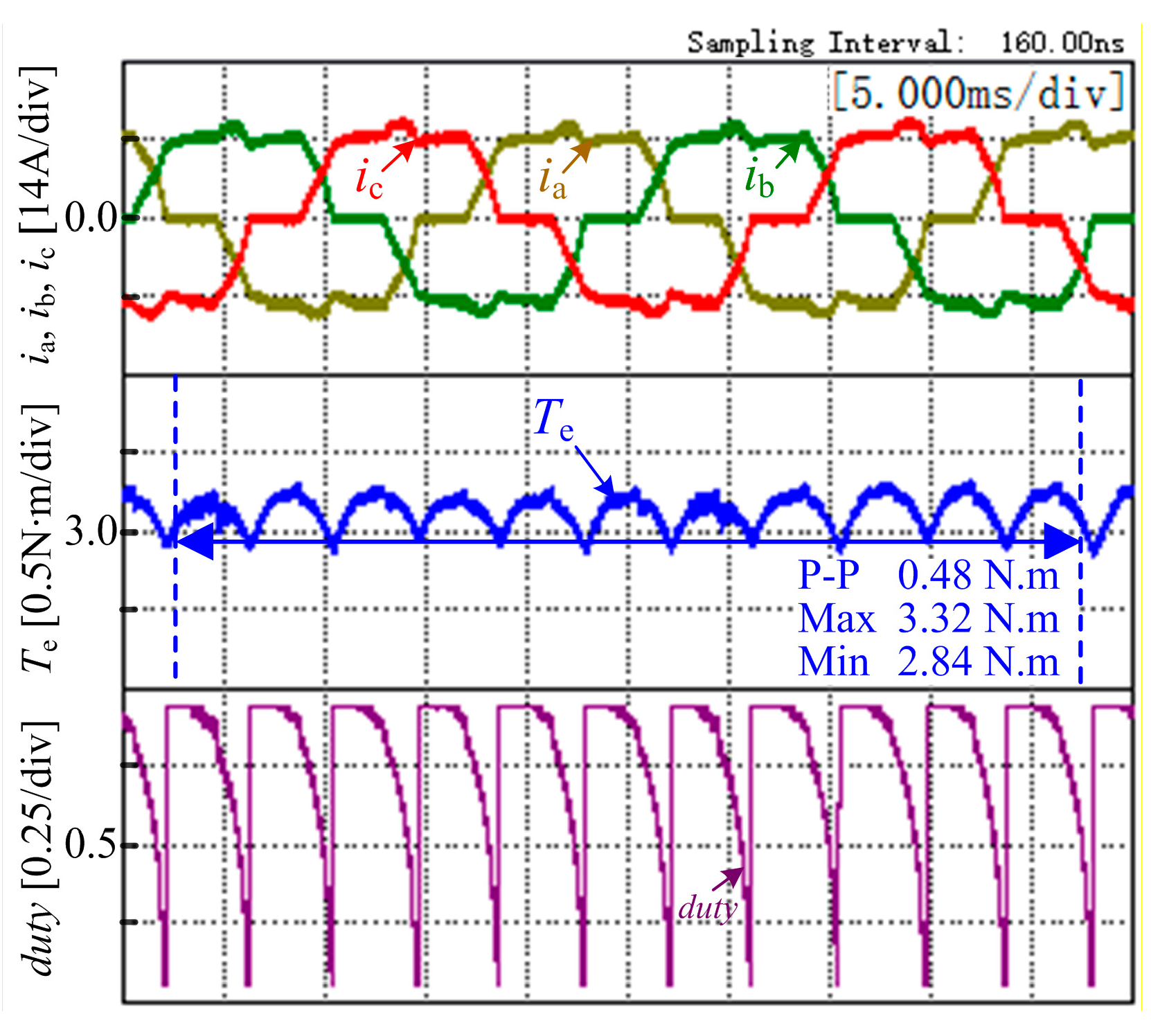
Figure 12 shows the experimental waveforms with the proposed strategy under the rated load at 600 r/min. As shown in
Figure 12, the torque ripple rate is 7.792%, which indicates the proposed strategy can suppress the torque ripple effectively, and the phenomenon that the outgoing phase current cannot be reduced to zero does not appear under rated conditions by the proposed strategy.
This paper considers the variation of the back-EMF in the commutation period, and the proposed strategy dynamically regulates the chopping duty cycle according to the variation trend of back-EMFs of three phases. Hence, the back-EMF coefficient is one of the important input parameters for the controller. To measure the back-EMF coefficient, driving by another motor at the speed 200 r/min,
Figure 13 shows the measured back-EMFs of three phases in the open circuit windings. The back-EMF coefficient
ke = 0.013V/(r/min) listed in
Table 1 can be calculated by this experimental result.
6. Conclusions
This paper aims to reduce the commutation torque ripple of BLDCM in its high-speed region, simultaneously broadening the valid speed range of the torque ripple reduction strategy without increasing the DC voltage. This paper firstly analyzes the problems of the traditional commutation torque ripple suppression for the high-speed region in a long commutation duration. A novel commutation torque ripple reduction strategy is then proposed based on a reconstructed smooth torque mechanism with back-EMF variation considered. Compared with the traditional strategy which controls the chopping duty cycle relatively smoothly in the commutation process, the proposed strategy dynamically regulates the chopping duty cycle, which make it show a gradual decrease. The proposed strategy has the following contributions:
The effect of back-EMF variation on torque and outgoing phase current during the commutation process is theoretically analyzed, and the speed range for the normal end of commutation is further deduced.
The smooth torque mechanism is reconstructed with the back-EMF variation considered, based on which a new commutation torque ripple suppression strategy is further designed. The proposed strategy can guarantee the torque gradient to be zero (dTe/dt = 0) even under the changing back-EMF during the commutation process, which can more effectively reduce the commutation torque ripple.
The proposed strategy broadens the speed range for commutation torque ripple reduction, reducing the risk of phase current distortion and enhancing the reliability of the motor operation.
Author Contributions
Conceptualization, W.C., T.S., X.L and G.J.; methodology, X.L. and G.J.; software, G.J. and X.L.; validation, X.L., G.Z. and G.J.; formal analysis, G.Z. and Q.G.; writing—original draft preparation, G.J. and X.L.; writing—review and editing, G.Z., Q.G. and T.S.; funding acquisition, X.L., Q.G. and W.C.
Funding
This research was jointly supported in part by National Natural Science Foundation of China under Grant 51807141 and 51577126, in part by The Natural Science Foundation of Tianjin (18JCQNJC74200) and in part by The Science & Technology Development Fund of Tianjin Education Commission for Higher Education (2018KJ208).
Conflicts of Interest
The authors declare no conflict of interest.
References
- Zhu, Z.Q.; Howe, D. Electrical Machines and Drives for Electric, Hybrid, and Fuel Cell Vehicles. Proc. IEEE 2007, 95, 746–765. [Google Scholar] [CrossRef]
- Xia, C.; Jiang, G.; Chen, W.; Shi, T. Switching-Gain Adaptation Current Control for Brushless DC Motors. IEEE Trans. Ind. Electron. 2016, 63, 2044–2052. [Google Scholar] [CrossRef]
- Ustun, O.; Kivanc, O.; Senol, S.; Fincan, B. On Field Weakening Performance of a Brushless Direct Current Motor with Higher Winding Inductance: Why Does Design Matter. Energies 2018, 11, 3119. [Google Scholar] [CrossRef]
- Yoon, K.; Baek, S. Robust Design Optimization with Penalty Function for Electric Oil Pumps with BLDC Motors. Energies 2019, 12, 153. [Google Scholar] [CrossRef]
- Priyadarshi, N.; Padmanaban, S.; Mihet-Popa, L.; Blaabjerg, F.; Azam, F. Maximum Power Point Tracking for Brushless DC Motor-Driven Photovoltaic Pumping Systems Using a Hybrid ANFIS-FLOWER Pollination Optimization Algorithm. Energies 2018, 11, 1067. [Google Scholar] [CrossRef]
- Kamalapathi, K.; Priyadarshi, N.; Padmanaban, S.; Holm-Nielsen, J.; Azam, F.; Umayal, C.; Ramachandaramurthy, V. A Hybrid Moth-Flame Fuzzy Logic Controller Based Integrated Cuk Converter Fed Brushless DC Motor for Power Factor Correction. Electronics 2018, 7, 288. [Google Scholar] [CrossRef]
- Carlson, R.; Mazenc, M.L.; Fagundes, J.C.D.S. Analysis of torque ripple due to phase commutation in brushless DC machines. IEEE Trans. Ind. Appl. 1992, 28, 632–638. [Google Scholar] [CrossRef]
- Liu, Y.; Zhu, Z.Q.; Howe, D. Commutation-Torque-Ripple Minimization in Direct-Torque-Controlled PM Brushless DC Drives. IEEE Trans. Ind. Appl. 2007, 43, 1012–1021. [Google Scholar] [CrossRef]
- Jung, S.; Kim, Y.; Jae, J.; Kim, J. Commutation Control for the Low-Commutation Torque Ripple in the Position Sensorless Drive of the Low-Voltage Brushless DC Motor. IEEE Trans. Power Electron. 2014, 29, 5983–5994. [Google Scholar] [CrossRef]
- Li, H.; Zheng, S.; Ren, H. Self-Correction of Commutation Point for High-Speed Sensorless BLDC Motor with Low Inductance and Nonideal Back EMF. IEEE Trans. Power Electron. 2017, 32, 642–651. [Google Scholar] [CrossRef]
- Cao, Y.; Shi, T.; Li, X.; Chen, W.; Xia, C. A Commutation Torque Ripple Suppression Strategy for Brushless DC Motor Based on Diode-Assisted Buck–Boost Inverter. IEEE Trans. Power Electron. 2019, 34, 5594–5605. [Google Scholar] [CrossRef]
- Tan, B.; Hua, Z.; Zhang, L.; Fang, C. A New Approach of Minimizing Commutation Torque Ripple for BLDCM. Energies 2017, 10, 1735. [Google Scholar] [CrossRef]
- Jiang, G.; Xia, C.; Chen, W.; Shi, T.; Li, X.; Cao, Y. Commutation Torque Ripple Suppression Strategy for Brushless DC Motors with a Novel Noninductive Boost Front End. IEEE Trans. Power Electron. 2018, 33, 4274–4284. [Google Scholar] [CrossRef]
- Shi, T.; Cao, Y.; Jiang, G.; Li, X.; Xia, C. A Torque Control Strategy for Torque Ripple Reduction of Brushless DC Motor with Nonideal Back Electromotive Force. IEEE Trans. Ind. Electron. 2017, 64, 4423–4433. [Google Scholar] [CrossRef]
- Song, J.H.; Choy, I. Commutation Torque Ripple Reduction in Brushless DC Motor Drives Using a Single DC Current Sensor. IEEE Trans. Power Electron. 2004, 19, 312–319. [Google Scholar] [CrossRef]
- Shi, J.; Li, T. New Method to Eliminate Commutation Torque Ripple of Brushless DC Motor with Minimum Commutation Time. IEEE Trans. Ind. Electron. 2013, 60, 2139–2146. [Google Scholar] [CrossRef]
- Xia, C.; Xiao, Y.; Chen, W.; Shi, T. Torque Ripple Reduction in Brushless DC Drives Based on Reference Current Optimization Using Integral Variable Structure Control. IEEE Trans. Ind. Electron. 2014, 61, 738–752. [Google Scholar] [CrossRef]
- Lin, Y.; Lai, Y. Pulsewidth Modulation Technique for BLDCM Drives to Reduce Commutation Torque Ripple Without Calculation of Commutation Time. IEEE Trans. Ind. Applicat. 2011, 47, 1786–1793. [Google Scholar] [CrossRef]
- Nam, K.Y.; Lee, W.T.; Lee, C.M.; Hong, J.P. Reducing torque ripple of brushless DC motor by varying input voltage. IEEE Trans. Magn. 2006, 42, 1307–1310. [Google Scholar] [CrossRef]
- Shi, T.; Guo, Y.; Song, P.; Xia, C. A New Approach of Minimizing Commutation Torque Ripple for Brushless DC Motor Based on DC–DC Converter. IEEE Trans. Ind. Electron. 2010, 57, 3483–3490. [Google Scholar] [CrossRef]
- Viswanathan, V.; Jeevananthan, S. Approach for torque ripple reduction for brushless DC motor based on three-level neutral-point-clamped inverter with DC-DC converter. IET Power Electron. 2015, 8, 47–55. [Google Scholar] [CrossRef]
- Xiaofeng, Z.; Lu, Z. A New BLDC Motor Drives Method Based on BUCK Converter for Torque Ripple Reduction. In Proceedings of the 2006 CES/IEEE 5th International Power Electronics and Motion Control Conference, Shanghai, China, 14–16 August 2006; pp. 1–4. [Google Scholar]
- Li, X.; Xia, C.; Cao, Y.; Chen, W.; Shi, T. Commutation Torque Ripple Reduction Strategy of Z-Source Inverter Fed Brushless DC Motor. IEEE Trans. Power Electron. 2016, 31, 7677–7690. [Google Scholar] [CrossRef]
- Kang, B.H.; Kim, C.J.; Mok, H.S.; Choe, G.H. Analysis of torque ripple in BLDC motor with commutation time. In Proceedings of the IEEE International Symposium on Industrial Electronics (ISIE), Pusan, South Korea, 12–16 June 2001. [Google Scholar] [CrossRef]
© 2019 by the authors. Licensee MDPI, Basel, Switzerland. This article is an open access article distributed under the terms and conditions of the Creative Commons Attribution (CC BY) license (http://creativecommons.org/licenses/by/4.0/).


