Recent Advances in Layer-by-Layer Assembled Conducting Polymer Based Composites for Supercapacitors


Abstract
:
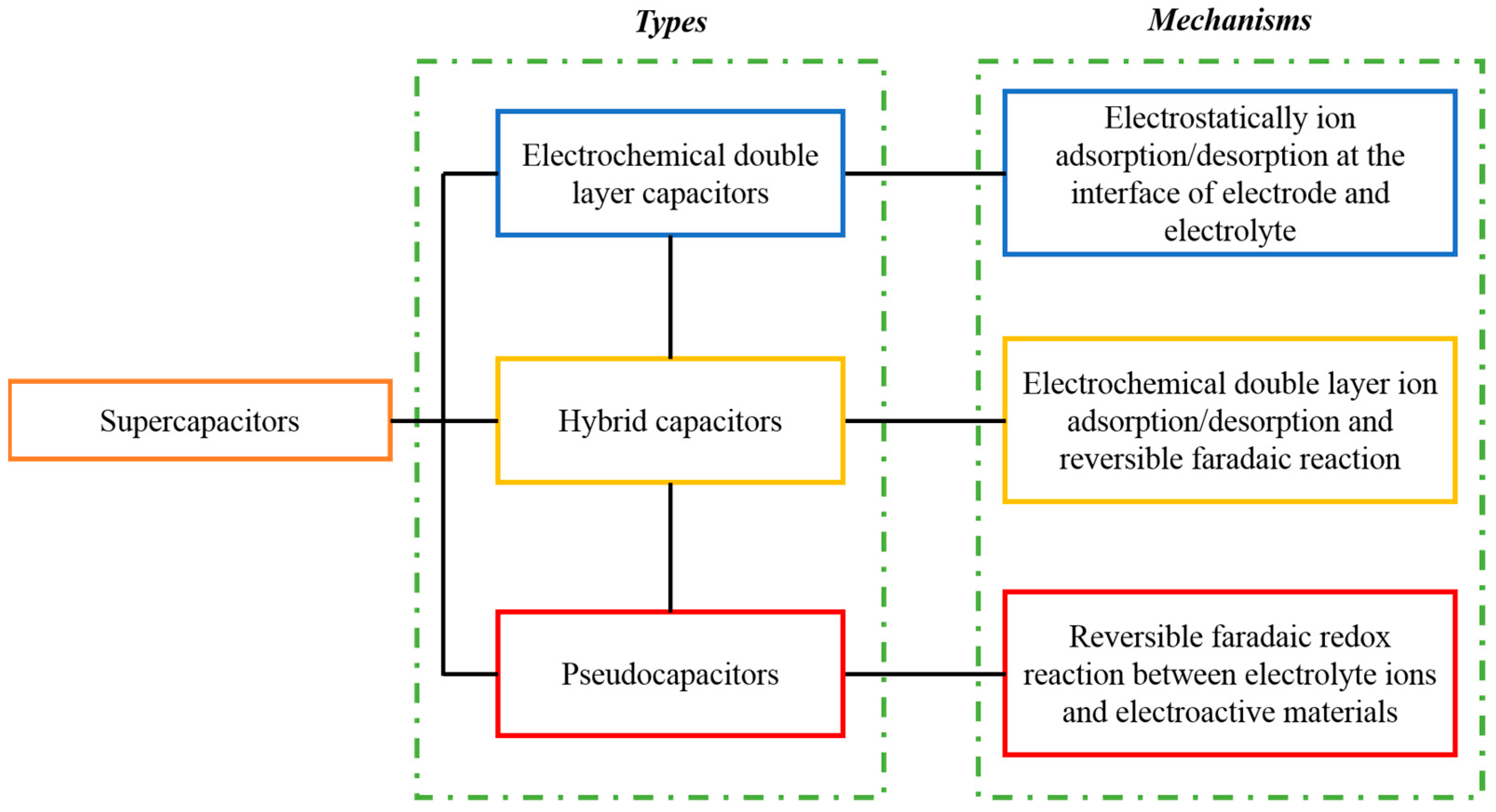
1. Introduction
Supercapacitor
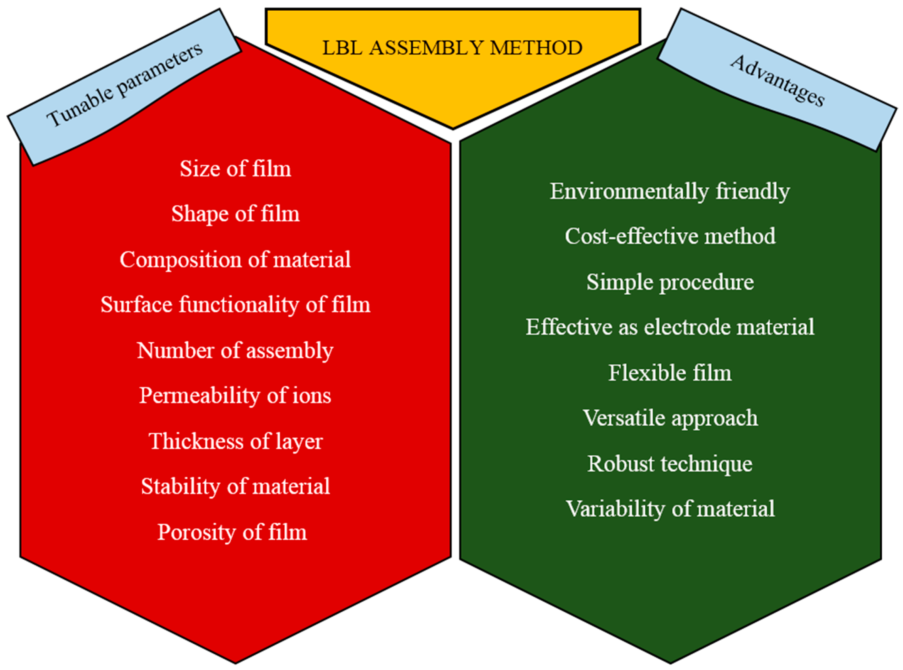
2. Layer by Layer Assembly
2.1. Introduction
2.2. Overview of Layer by Layer Assembly
2.3. Techniques of Assembly
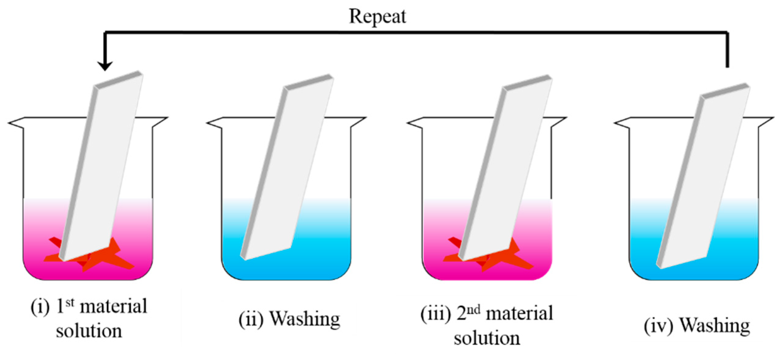
2.3.1. Dip-Coating
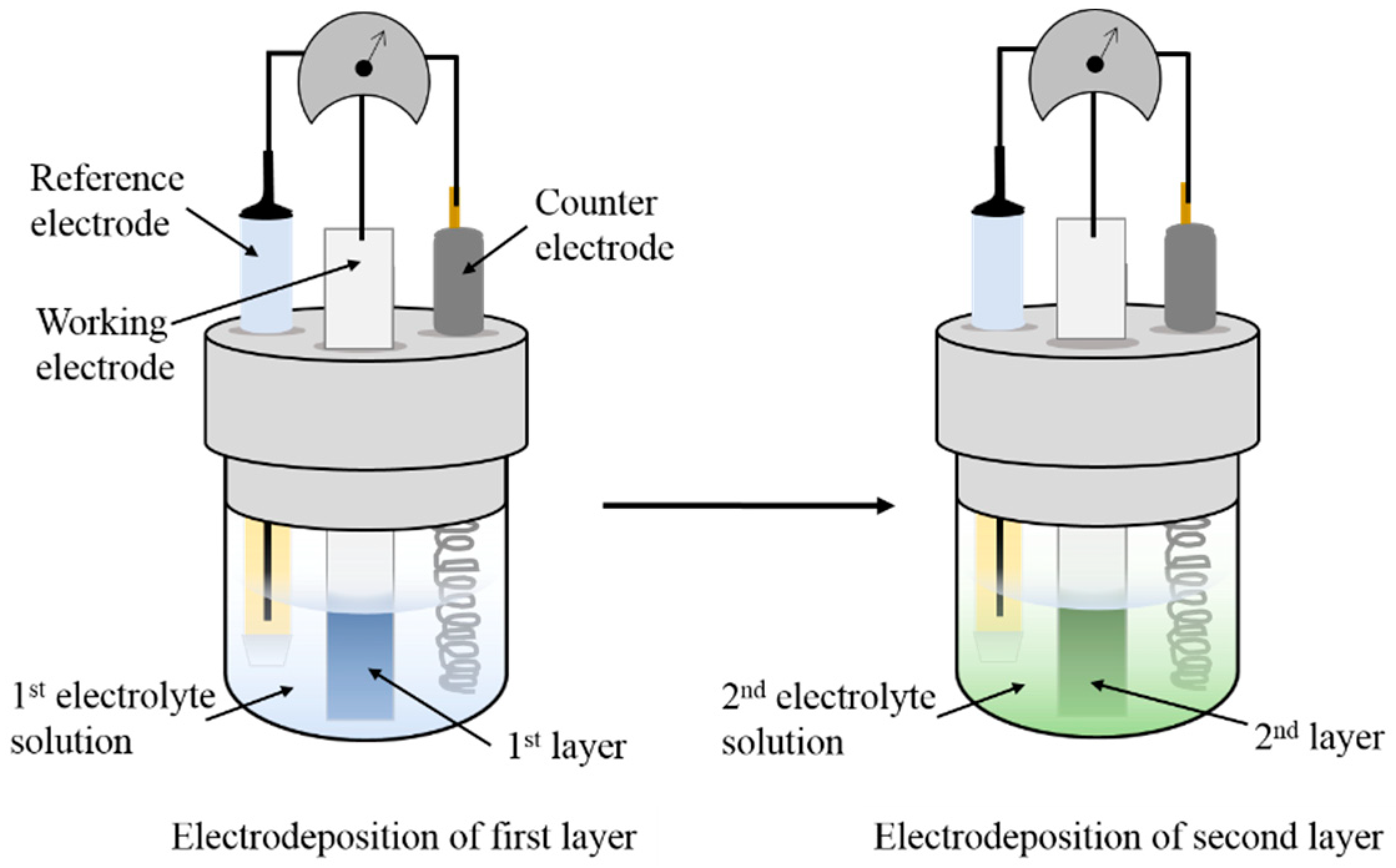
2.3.2. Electrodeposition
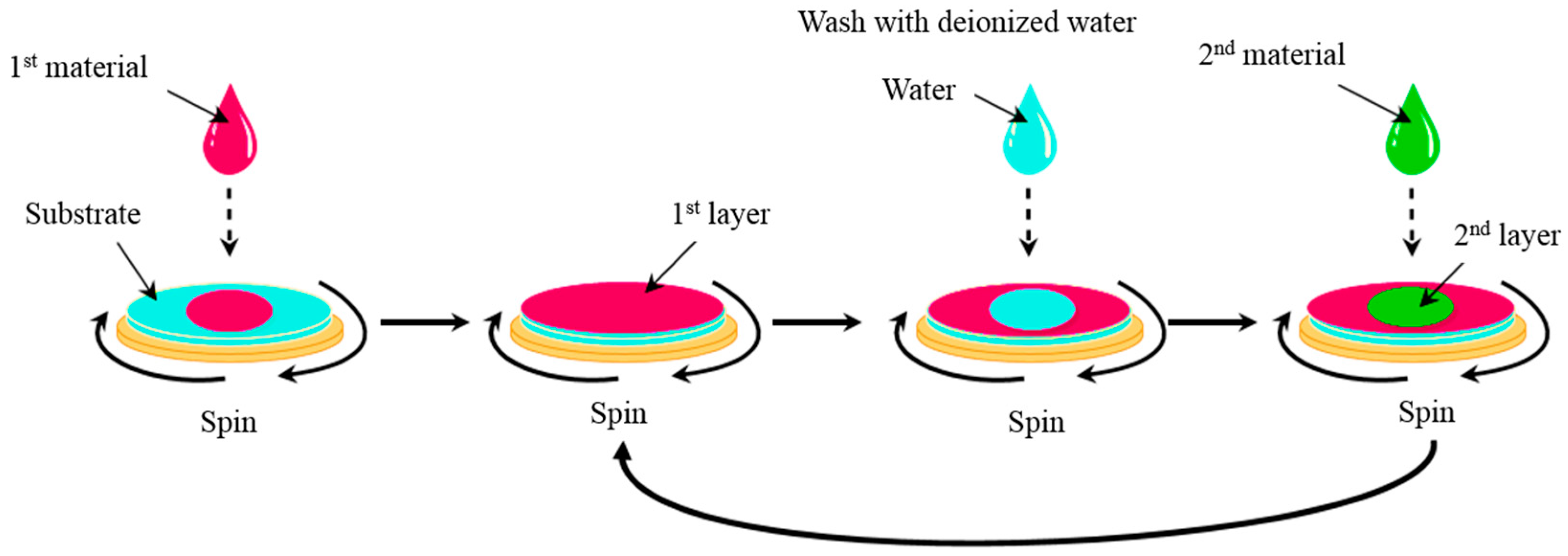
2.3.3. Spin Coating
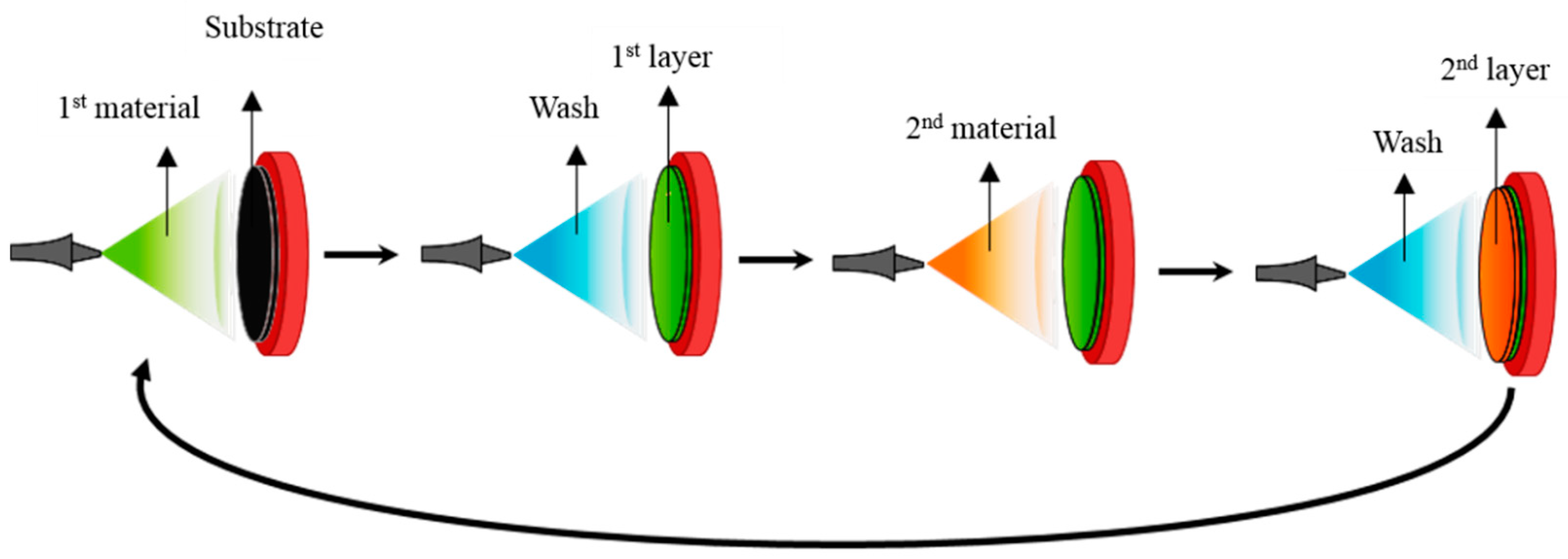
2.3.4. Spray Assembly
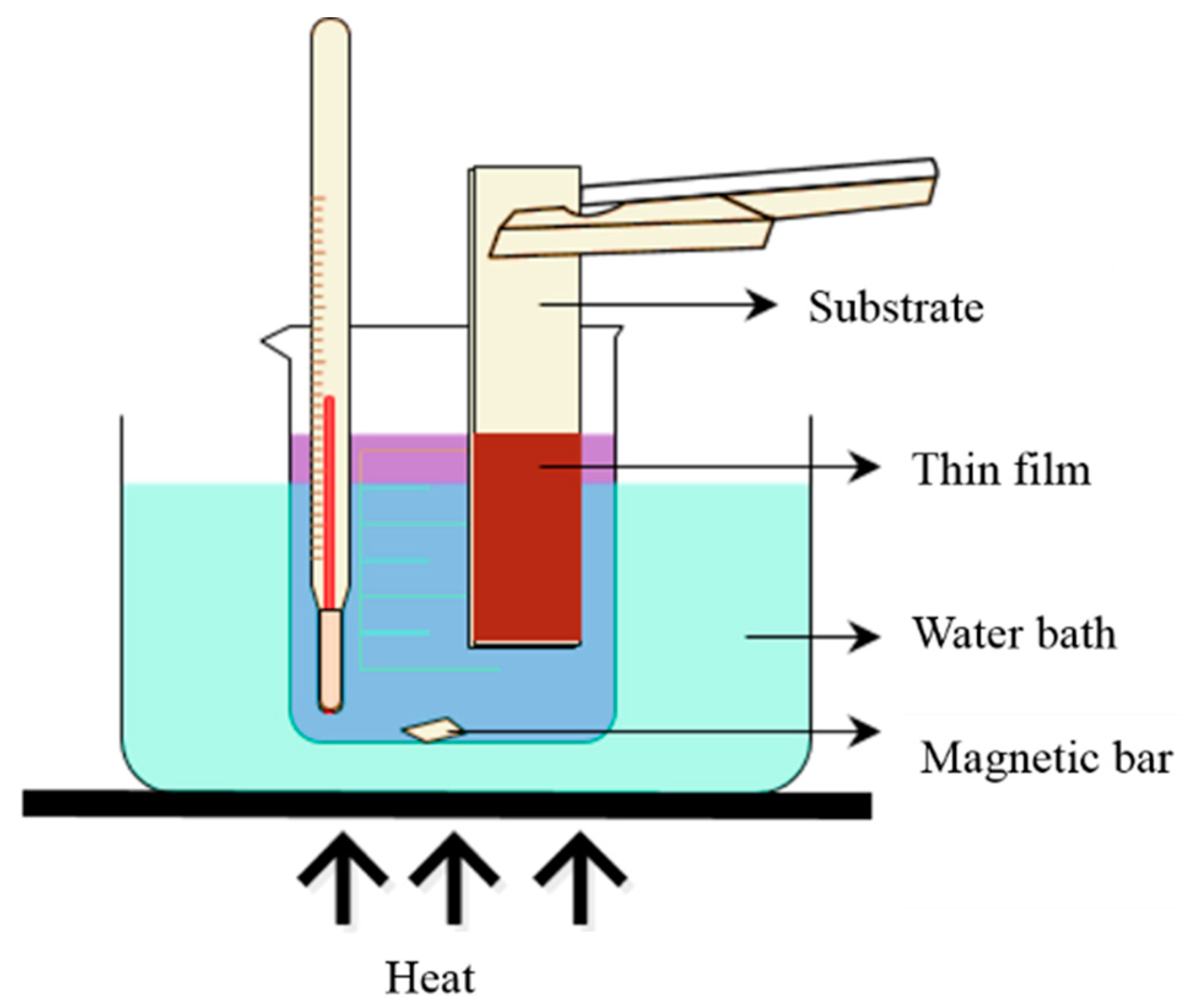
2.3.5. Chemical Bath Deposition (CBD)
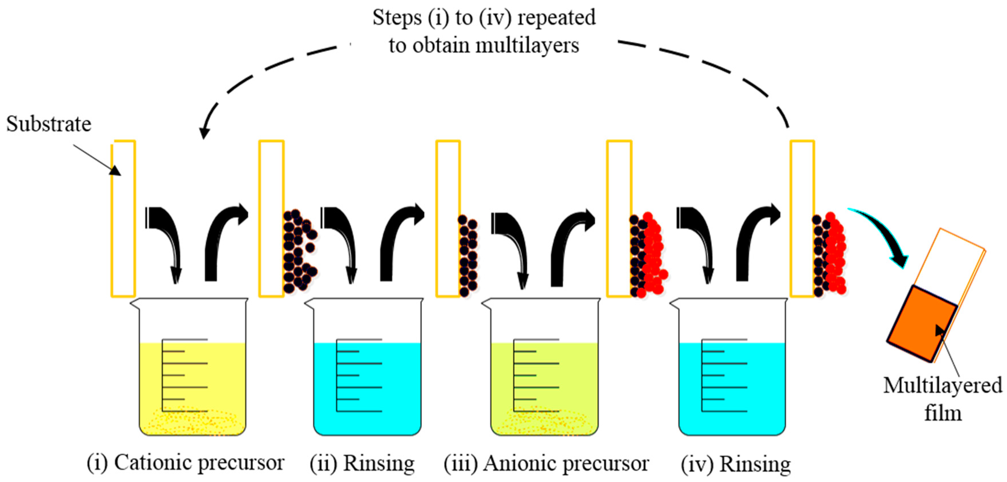
2.3.6. Successive Ionic Layer Adsorption and Reaction (SILAR)
2.3.7. Other Techniques
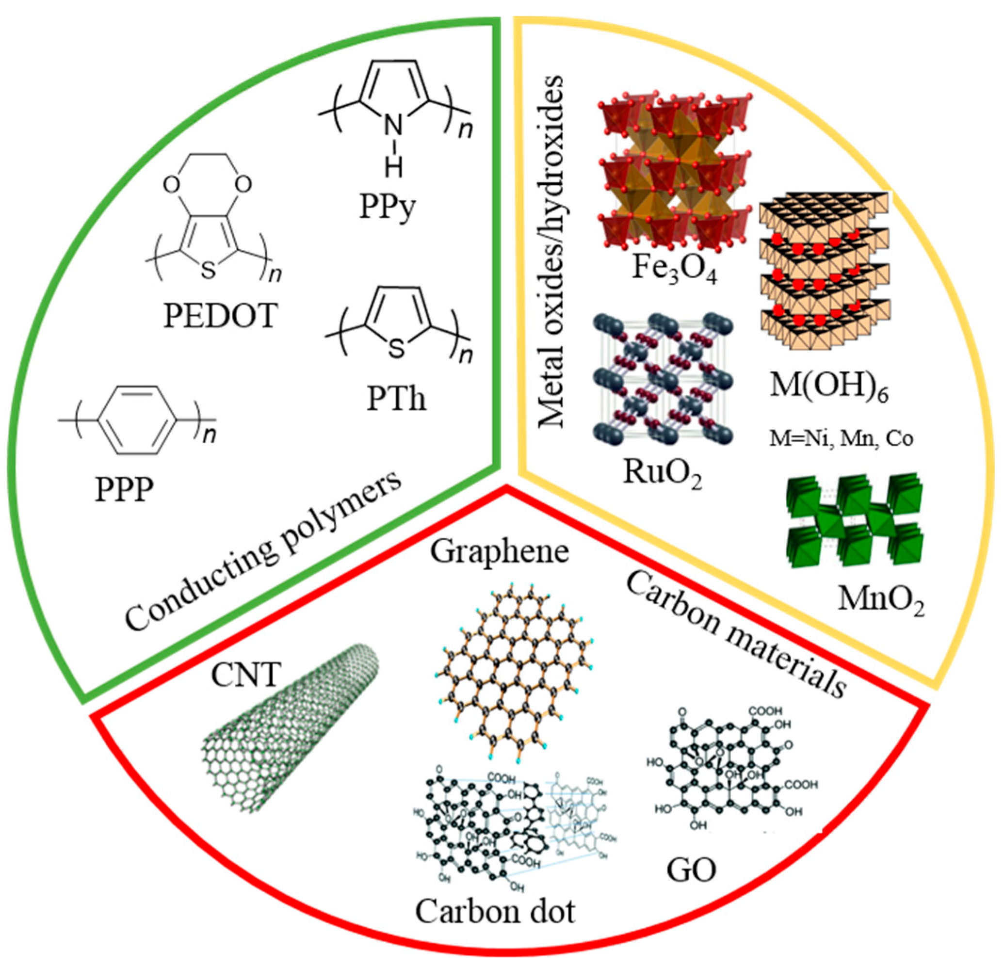
3. Conducting Polymer
3.1. Conducting Polymer-Based LBL Multilayers
3.1.1. Conducting Polymer-Conducting Polymer Based LBL
3.1.2. Conducting Polymer-Carbon Based LBL
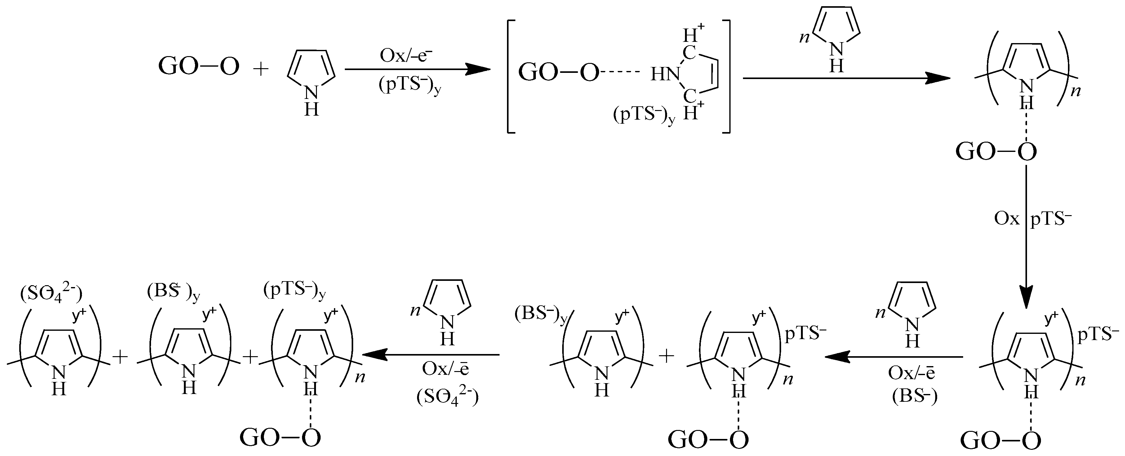
- The p-toluene sulfonate ions with bigger size which densely pack inside PPy were chosen as the first layer. This criterion assists in increasing the capacitance and conductivity of the composite.
- The second layer with smaller sized counter ions (benzene sulfonate ions) form highly p-doped PPy as the smaller ions donate electrons easily.
- Complete dissociation of sulfuric acid (final layer) allows sufficient space for the ions to be electrostatically adsorbed onto the pore layer of the composites.
3.1.3. Conducting Polymer-Metal Oxides Based LBL
4. Conclusions: Summary and Perspectives
- The main issue in fabricating a supercapacitor is the high cost. Fabricating more cost-effective LBL assembled CP-based composites needs to be considered.
- Commonly, the electrode material for a supercapacitor suffers from high transport resistance. In order to achieve a supercapacitor with low transport resistance, an electrode material with minimum thickness is important.
- An environmentally friendly approach and environmentally suitable materials are preferred. Overall we should pay more attention to the fabrication of LBL assembled CP-based composites in a more environmentally friendly approach.
- More importance should be placed on the selection of electrolyte. Choosing the correct electrolyte for the electrode determines the performance of the supercapacitor.
Author Contributions
Acknowledgments
Conflicts of Interest
References
- Simon, P.; Gogotsi, Y. Materials for electrochemical capacitors. Nat. Mater. 2008, 7, 845–854. [Google Scholar] [CrossRef] [PubMed] [Green Version]
- Wei, T.-Y.; Chen, C.-H.; Chien, H.-C.; Lu, S.-Y.; Hu, C.-C. A Cost-Effective Supercapacitor Material of Ultrahigh Specific Capacitances: Spinel Nickel Cobaltite Aerogels from an Epoxide-Driven Sol–Gel Process. Adv. Mat. 2010, 22, 347–351. [Google Scholar] [CrossRef] [PubMed]
- Yu, Z.; Duong, B.; Abbitt, D.; Thomas, J. Highly Ordered MnO2 Nanopillars for Enhanced Supercapacitor Performance. Adv. Mat. 2013, 25, 3302–3306. [Google Scholar] [CrossRef] [PubMed]
- Zhang, L.L.; Zhao, X.S. Carbon-based materials as supercapacitor electrodes. Chem. Soc. Rev. 2009, 38, 2520–2531. [Google Scholar] [CrossRef] [PubMed]
- Winter, M.; Brodd, R.J. What are batteries, fuel cells, and supercapacitors? Chem. Rev. 2004, 104, 4245–4269. [Google Scholar] [CrossRef] [PubMed]
- Largeot, C.; Portet, C.; Chmiola, J.; Taberna, P.L.; Gogotsi, Y.; Simon, P. Relation between the ion size and pore size for an electric double-layer capacitor. J. Am. Chem. Soc. 2008, 130, 2730–2731. [Google Scholar] [CrossRef] [PubMed]
- Kötz, R.; Carlen, M. Principles and applications of electrochemical capacitors. Electrochim. Acta 2000, 45, 2483–2498. [Google Scholar] [CrossRef]
- Qu, Q.T.; Wang, B.; Yang, L.C.; Shi, Y.; Tian, S.; Wu, Y.P. Study on electrochemical performance of activated carbon in aqueous Li2SO4, Na2SO4 and K2SO4 electrolytes. Electrochem. Commun. 2008, 10, 1652–1655. [Google Scholar] [CrossRef]
- Lin, C.; Ritter, J.A.; Popov, B.N. Correlation of Double-Layer Capacitance with the Pore Structure of Sol-Gel Derived Carbon Xerogels. J. Electrochem. Soc. 1999, 146, 3639–3643. [Google Scholar] [CrossRef]
- Shiraishi, S.; Kurihara, H.; Shi, L.; Nakayama, T.; Oya, A. Electric Double-Layer Capacitance of Meso/Macroporous Activated Carbon Fibers Prepared by the Blending Method: I. Nickel-Loaded Activated Carbon Fibers in Propylene Carbonate Solution Containing LiClO4 Salt. J. Electrochem. Soc. 2002, 149, A855–A861. [Google Scholar] [CrossRef]
- Yang, C.-M.; Kim, Y.-J.; Endo, M.; Kanoh, H.; Yudasaka, M.; Iijima, S.; Kaneko, K. Nanowindow-Regulated Specific Capacitance of Supercapacitor Electrodes of Single-Wall Carbon Nanohorns. J. Am. Chem. Soc. 2007, 129, 20–21. [Google Scholar] [CrossRef] [PubMed]
- Yu, G.; Xie, X.; Pan, L.; Bao, Z.; Cui, Y. Hybrid nanostructured materials for high-performance electrochemical capacitors. Nano Energy 2013, 2, 213–234. [Google Scholar] [CrossRef]
- Lei, C.; Wilson, P.; Lekakou, C. Effect of poly(3,4-ethylenedioxythiophene) (PEDOT) in carbon-based composite electrodes for electrochemical supercapacitors. J. Power Sources 2011, 196, 7823–7827. [Google Scholar] [CrossRef] [Green Version]
- Conway, B.E.; Pell, W.G. Double-layer and pseudocapacitance types of electrochemical capacitors and their applications to the development of hybrid devices. J. Solid State Electrochem. 2003, 7, 637–644. [Google Scholar] [CrossRef]
- Viswanathan, B. Chapter 13—Supercapacitors. In Energy Sources; Elsevier: Amsterdam, The Netherlands, 2017; pp. 315–328. [Google Scholar]
- Conway, B.E. Electrochemical Supercapacitors: Scientific Fundamentals and Technological Applications; Springer Science & Business Media: Berlin, Germany, 2013. [Google Scholar]
- Peng, S.; Fan, L.; Wei, C.; Liu, X.; Zhang, H.; Xu, W.; Xu, J. Flexible polypyrrole/copper sulfide/bacterial cellulose nanofibrous composite membranes as supercapacitor electrodes. Carbohydr. Polym. 2017, 157, 344–352. [Google Scholar] [CrossRef] [PubMed]
- Snook, G.A.; Kao, P.; Best, A.S. Conducting-polymer-based supercapacitor devices and electrodes. J. Power Sources 2011, 196, 1–12. [Google Scholar] [CrossRef]
- Zhang, S. Status, Opportunities, and Challenges of Electrochemical Energy Storage. Front. Energy Res. 2013, 1, 8. [Google Scholar]
- Zhao, C.; Ren, F.; Xue, X.; Zheng, W.; Wang, X.; Chang, L. A high-performance asymmetric supercapacitor based on Co(OH)2/graphene and activated carbon electrodes. J. Electroanal. Chem. 2016, 782, 98–102. [Google Scholar] [CrossRef]
- Katz, H.E.; Searson, P.C.; Poehler, T.O. Batteries and charge storage devices based on electronically conducting polymers. J. Mat. Res. 2010, 25, 1561–1574. [Google Scholar] [CrossRef]
- Qian, Y.; Liu, R.; Wang, Q.; Xu, J.; Chen, D.; Shen, G. Efficient synthesis of hierarchical NiO nanosheets for high-performance flexible all-solid-state supercapacitors. J. Mater. Chem. A 2014, 2, 10917–10922. [Google Scholar] [CrossRef]
- Zhang, G.; Lou, X.W. General Solution Growth of Mesoporous NiCo2O4 Nanosheets on Various Conductive Substrates as High-Performance Electrodes for Supercapacitors. Adv. Mat. 2013, 25, 976–979. [Google Scholar] [CrossRef] [PubMed]
- Heydari, H.; Moosavifard, S.E.; Elyasi, S.; Shahraki, M. Nanoporous CuS nano-hollow spheres as advanced material for high-performance supercapacitors. Appl. Surf. Sci. 2017, 394, 425–430. [Google Scholar] [CrossRef]
- Kopczyński, K.; Kolanowski, Ł.; Baraniak, M.; Lota, K.; Sierczyńska, A.; Lota, G. Highly amorphous PbO2 as an electrode in hybrid electrochemical capacitors. Curr. Appl. Phys. 2017, 17, 66–71. [Google Scholar] [CrossRef]
- Chen, J.; Jia, C.; Wan, Z. The preparation and electrochemical properties of MnO2/poly(3,4-ethylenedioxythiophene)/multiwalled carbon nanotubes hybrid nanocomposite and its application in a novel flexible micro-supercapacitor. Electrochim. Acta 2014, 121, 49–56. [Google Scholar] [CrossRef]
- Zhang, X.; Zeng, X.; Yang, M.; Qi, Y. Investigation of a Branchlike MoO3/Polypyrrole Hybrid with Enhanced Electrochemical Performance Used as an Electrode in Supercapacitors. ACS Appl. Mater. Interfaces 2014, 6, 1125–1130. [Google Scholar] [CrossRef]
- Karade, S.S.; Sankapal, B.R. Room temperature PEDOT:PSS encapsulated MWCNTs thin film for electrochemical supercapacitor. J. Electroanal. Chem. 2016, 771, 80–86. [Google Scholar] [CrossRef]
- Zhong, C.; Deng, Y.; Hu, W.; Qiao, J.; Zhang, L.; Zhang, J. A review of electrolyte materials and compositions for electrochemical supercapacitors. Chem. Soc. Rev. 2015, 44, 7484–7539. [Google Scholar] [CrossRef]
- Srivastava, S.; Kotov, N.A. Layer-by-layer (LBL) assembly with semiconductor nanoparticles and nanowires. In Semiconductor Nanocrystal Quantum Dots: Synthesis, Assembly, Spectroscopy and Applications; Springer: Berlin, Germany, 2008; pp. 197–216. [Google Scholar]
- Whitesides, G.M.; Kriebel, J.K.; Mayers, B.T. Self-Assembly and Nanostructured Materials. In Nanoscale Assembly: Chemical Techniques; Springer: Berlin, Germany, 2005; pp. 217–239. [Google Scholar]
- Iler, R.K. Multilayers of colloidal particles. J. Colloid Interface Sci. 1966, 21, 569–594. [Google Scholar] [CrossRef]
- Zhang, S. Fabrication of novel biomaterials through molecular self-assembly. Nat. Biotech. 2003, 21, 1171–1178. [Google Scholar] [CrossRef]
- Lin, N.; Stepanow, S. Design Low-dimensional Nanostructures at Surfaces by Supramolecular Chemistry. Oxford Handb. Nanosci. Technol. Front. Adv. 2010, 1, 278–305. [Google Scholar]
- Shimomura, M.; Sawadaishi, T. Bottom-up strategy of materials fabrication: A new trend in nanotechnology of soft materials. Curr. Opin. Colloid Interface Sci. 2001, 6, 11–16. [Google Scholar] [CrossRef]
- Zhang, S. Building from the bottom up. Mater. Today 2003, 6, 20–27. [Google Scholar] [CrossRef]
- Park, J.Y.; Advincula, R.C. Nanostructuring polymers, colloids, and nanomaterials at the air–water interface through Langmuir and Langmuir–Blodgett techniques. Soft Matter 2011, 7, 9829–9843. [Google Scholar] [CrossRef]
- Ariga, K.; Yamauchi, Y.; Mori, T.; Hill, J.P. 25th Anniversary Article: What Can Be Done with the Langmuir-Blodgett Method? Recent Developments and its Critical Role in Materials Science. Adv. Mat. 2013, 25, 6477–6512. [Google Scholar] [CrossRef] [PubMed]
- Cheng, X.; Lowe, S.B.; Reece, P.J.; Gooding, J.J. Colloidal silicon quantum dots: From preparation to the modification of self-assembled monolayers (SAMs) for bio-applications. Chem. Soc. Rev. 2014, 43, 2680–2700. [Google Scholar] [CrossRef] [PubMed]
- Hamoudi, H.; Uosaki, K.; Ariga, K.; Esaulov, V.A. Going beyond the self-assembled monolayer: Metal intercalated dithiol multilayers and their conductance. RSC Adv. 2014, 4, 39657–39666. [Google Scholar] [CrossRef]
- Ariga, K.; Ji, Q.; Nakanishi, W.; Hill, J.P. Thin Film Nanoarchitectonics. J. Inorg. Organomet. Polym. Mater. 2015, 25, 466–479. [Google Scholar] [CrossRef]
- Xiang, Y.; Lu, S.; Jiang, S.P. Layer-by-layer self-assembly in the development of electrochemical energy conversion and storage devices from fuel cells to supercapacitors. Chem. Soc. Rev. 2012, 41, 7291–7321. [Google Scholar] [CrossRef]
- Iler, R.K. Adsorption of Colloidal Silica on Alumina and of Colloidal Alumina on Silica. J. Am. Ceram. Soc. 1964, 47, 194–198. [Google Scholar] [CrossRef]
- Decher, G.; Hong, J.-D. Buildup of ultrathin multilayer films by a self-assembly process, 1 consecutive adsorption of anionic and cationic bipolar amphiphiles on charged surfaces. Makromol. Chem. Macromol. Symp. 1991, 46, 321–327. [Google Scholar] [CrossRef]
- Decher, G.; Hong, J.D. Buildup of Ultrathin Multilayer Films by a Self-Assembly Process: II. Consecutive Adsorption of Anionic and Cationic Bipolar Amphiphiles and Polyelectrolytes on Charged Surfaces. Ber. Bunsengesellschaft Phys. Chem. 1991, 95, 1430–1434. [Google Scholar] [CrossRef]
- Decher, G.; Hong, J.D.; Schmitt, J. Buildup of ultrathin multilayer films by a self-assembly process: III. Consecutively alternating adsorption of anionic and cationic polyelectrolytes on charged surfaces. Thin Solid Films 1992, 210, 831–835. [Google Scholar] [CrossRef]
- Schönhoff, M. Self-assembled polyelectrolyte multilayers. Curr. Opin. Colloid Interface Sci. 2003, 8, 86–95. [Google Scholar] [CrossRef]
- Irigoyen, J.; Politakos, N.; Diamanti, E.; Rojas, E.; Marradi, M.; Ledezma, R.; Arizmendi, L.; Rodríguez, J.A.; Ziolo, R.F.; Moya, S.E. Fabrication of hybrid graphene oxide/polyelectrolyte capsules by means of layer-by-layer assembly on erythrocyte cell templates. Beilstein J. Nanotechnol. 2015, 6, 2310–2318. [Google Scholar] [CrossRef] [PubMed]
- Ariga, K.; Yamauchi, Y.; Rydzek, G.; Ji, Q.; Yonamine, Y.; Wu, K.C.W.; Hill, J.P. Layer-by-layer Nanoarchitectonics: Invention, Innovation, and Evolution. Chem. Lett. 2014, 43, 36–68. [Google Scholar] [CrossRef]
- Decher, G. Fuzzy Nanoassemblies: Toward Layered Polymeric Multicomposites. Science 1997, 277, 1232–1237. [Google Scholar] [CrossRef]
- Wang, L.; Wang, Z.; Zhang, X.; Shen, J.; Chi, L.; Fuchs, H. A new approach for the fabrication of an alternating multilayer film of poly(4-vinylpyridine) and poly(acrylic acid) based on hydrogen bonding. Macromol. Rapid Commun. 1997, 18, 509–514. [Google Scholar] [CrossRef]
- Shim, B.S.; Zhu, J.; Jan, E.; Critchley, K.; Kotov, N.A. Transparent Conductors from Layer-by-Layer Assembled SWNT Films: Importance of Mechanical Properties and a New Figure of Merit. ACS Nano 2010, 4, 3725–3734. [Google Scholar] [CrossRef]
- Zhu, J.; He, J. Assembly and benign step-by-step post-treatment of oppositely charged reduced graphene oxides for transparent conductive thin films with multiple applications. Nanoscale 2012, 4, 3558–3566. [Google Scholar] [CrossRef]
- Borges, J.; Mano, J.F. Molecular Interactions Driving the Layer-by-Layer Assembly of Multilayers. Chem. Rev. 2014, 114, 8883–8942. [Google Scholar] [CrossRef]
- Kharlampieva, E.; Kozlovskaya, V.; Sukhishvili, S.A. Layer-by-Layer Hydrogen-Bonded Polymer Films: From Fundamentals to Applications. Adv. Mat. 2009, 21, 3053–3065. [Google Scholar] [CrossRef]
- Izquierdo, A.; Ono, S.S.; Voegel, J.C.; Schaaf, P.; Decher, G. Dipping versus Spraying: Exploring the Deposition Conditions for Speeding Up Layer-by-Layer Assembly. Langmuir 2005, 21, 7558–7567. [Google Scholar] [CrossRef] [PubMed]
- Xiao, F.-X.; Pagliaro, M.; Xu, Y.-J.; Liu, B. Layer-by-layer assembly of versatile nanoarchitectures with diverse dimensionality: A new perspective for rational construction of multilayer assemblies. Chem. Soc. Rev. 2016, 45, 3088–3121. [Google Scholar] [CrossRef]
- Ge, J.; Yao, H.-B.; Hu, W.; Yu, X.-F.; Yan, Y.-X.; Mao, L.-B.; Li, H.-H.; Li, S.-S.; Yu, S.-H. Facile dip coating processed graphene/MnO2 nanostructured sponges as high performance supercapacitor electrodes. Nano Energy 2013, 2, 505–513. [Google Scholar] [CrossRef]
- Xu, L.-L.; Guo, M.-X.; Liu, S.; Bian, S.-W. Graphene/cotton composite fabrics as flexible electrode materials for electrochemical capacitors. RSC Adv. 2015, 5, 25244–25249. [Google Scholar] [CrossRef]
- Hyder, M.N.; Lee, S.W.; Cebeci, F.Ç.; Schmidt, D.J.; Shao-Horn, Y.; Hammond, P.T. Layer-by-Layer Assembled Polyaniline Nanofiber/Multiwall Carbon Nanotube Thin Film Electrodes for High-Power and High-Energy Storage Applications. ACS Nano 2011, 5, 8552–8561. [Google Scholar] [CrossRef] [PubMed]
- Sarker, A.K.; Hong, J.-D. Layer-by-Layer Self-Assembled Multilayer Films Composed of Graphene/Polyaniline Bilayers: High-Energy Electrode Materials for Supercapacitors. Langmuir 2012, 28, 12637–12646. [Google Scholar] [CrossRef] [PubMed]
- Byon, H.R.; Lee, S.W.; Chen, S.; Hammond, P.T.; Shao-Horn, Y. Thin films of carbon nanotubes and chemically reduced graphenes for electrochemical micro-capacitors. Carbon 2011, 49, 457–467. [Google Scholar] [CrossRef]
- Gallant, B.M.; Lee, S.W.; Kawaguchi, T.; Hammond, P.T.; Shao-Horn, Y. Electrochemical Performance of Thin-Film Functionalized Carbon Nanotube Electrodes in Nonaqueous Cells. J. Electrochem. Soc. 2014, 161, A1625–A1633. [Google Scholar] [CrossRef]
- Khoh, W.-H.; Hong, J.-D. Layer-by-layer self-assembly of ultrathin multilayer films composed of magnetite/reduced graphene oxide bilayers for supercapacitor application. Colloids Surf. A 2013, 436, 104–112. [Google Scholar] [CrossRef]
- Lee, S.W.; Kim, B.-S.; Chen, S.; Shao-Horn, Y.; Hammond, P.T. Layer-by-Layer Assembly of All Carbon Nanotube Ultrathin Films for Electrochemical Applications. J. Am. Chem. Soc. 2009, 131, 671–679. [Google Scholar] [CrossRef] [PubMed]
- Peng, S.; Fan, L.; Wei, C.; Bao, H.; Zhang, H.; Xu, W.; Xu, J. Polypyrrole/nickel sulfide/bacterial cellulose nanofibrous composite membranes for flexible supercapacitor electrodes. Cellulose 2016, 23, 2639–2651. [Google Scholar] [CrossRef]
- Xu, J.; Wang, D.; Yuan, Y.; Wei, W.; Duan, L.; Wang, L.; Bao, H.; Xu, W. Polypyrrole/reduced graphene oxide coated fabric electrodes for supercapacitor application. Org. Electron. 2015, 24, 153–159. [Google Scholar] [CrossRef]
- Fu, Y.; Li, S.-J.; Xu, J.; Yang, M.; Zhang, J.-D.; Jiao, Y.-H.; Zhang, J.-C.; Zhang, K.; Jia, Y.-G. Facile and Efficient Approach to Speed up Layer-by-Layer Assembly: Dipping in Agitated Solutions. Langmuir 2011, 27, 672–677. [Google Scholar] [CrossRef]
- Lee, S.W.; Kim, J.; Chen, S.; Hammond, P.T.; Shao-Horn, Y. Carbon Nanotube/Manganese Oxide Ultrathin Film Electrodes for Electrochemical Capacitors. ACS Nano 2010, 4, 3889–3896. [Google Scholar] [CrossRef] [PubMed]
- Zheng, H.; Tang, F.; Jia, Y.; Wang, L.; Chen, Y.; Lim, M.; Zhang, L.; Lu, G. Layer-by-layer assembly and electrochemical properties of sandwiched film of manganese oxide nanosheet and carbon nanotube. Carbon 2009, 47, 1534–1542. [Google Scholar] [CrossRef]
- Bohnenberger, T.; Schmid, U. Thin CNT-based Films Deposited with the Layer-by-Layer Technique for Supercapacitor Applications. Procedia Eng. 2015, 120, 1037–1041. [Google Scholar] [CrossRef] [Green Version]
- Wang, X.; Gao, K.; Shao, Z.; Peng, X.; Wu, X.; Wang, F. Layer-by-layer assembled hybrid multilayer thin film electrodes based on transparent cellulose nanofibers paper for flexible supercapacitors applications. J. Power Sources 2014, 249, 148–155. [Google Scholar] [CrossRef]
- Ye, X.; Zhou, Q.; Jia, C.; Tang, Z.; Wan, Z.; Wu, X. A Knittable Fibriform Supercapacitor Based on Natural Cotton Thread Coated with Graphene and Carbon Nanoparticles. Electrochim. Acta 2016, 206, 155–164. [Google Scholar] [CrossRef]
- Hong, J.; Kang, S.W. Hydrophobic properties of colloidal films coated with multi-wall carbon nanotubes/reduced graphene oxide multilayers. Colloids Surf. A 2011, 374, 54–57. [Google Scholar] [CrossRef]
- Zhang, W.; Mu, B.; Wang, A. Preparation of manganese dioxide/multiwalled carbon nanotubes hybrid hollow microspheres via layer-by-layer assembly for supercapacitor. J. Mat. Sci. 2013, 48, 7581–7586. [Google Scholar] [CrossRef]
- Luo, J.; Ma, Q.; Gu, H.; Zheng, Y.; Liu, X. Three-dimensional graphene-polyaniline hybrid hollow spheres by layer-by-layer assembly for application in supercapacitor. Electrochim. Acta 2015, 173, 184–192. [Google Scholar] [CrossRef]
- Tang, P.; Han, L.; Zhang, L. Facile Synthesis of Graphite/PEDOT/MnO2 Composites on Commercial Supercapacitor Separator Membranes as Flexible and High-Performance Supercapacitor Electrodes. ACS Appl. Mater. Interfaces 2014, 6, 10506–10515. [Google Scholar] [CrossRef] [PubMed]
- De la Fuente Salas, I.M.; Sudhakar, Y.N.; Selvakumar, M. High performance of symmetrical supercapacitor based on multilayer films of graphene oxide/polypyrrole electrodes. Appl. Surf. Sci. 2014, 296, 195–203. [Google Scholar] [CrossRef]
- Kulandaivalu, S.; Abdul Shukur, R.; Sulaiman, Y. Improved electrochemical performance of electrochemically designed layered poly(3,4-ethylenedioxythiophene)/graphene oxide with poly(3,4-ethylenedioxythiophene)/nanocrystalline cellulose nanocomposite. Synth. Met. 2018, 245, 24–31. [Google Scholar] [CrossRef]
- Kulandaivalu, S.; Suhaimi, N.; Sulaiman, Y. Unveiling high specific energy supercapacitor from layer-by-layer assembled polypyrrole/graphene oxide|polypyrrole/manganese oxide electrode material. Sci. Rep. 2019, 9, 4884. [Google Scholar] [CrossRef]
- Lim, Y.S.; Tan, Y.P.; Lim, H.N.; Huang, N.M.; Tan, W.T.; Yarmo, M.A.; Yin, C.-Y. Potentiostatically deposited polypyrrole/graphene decorated nano-manganese oxide ternary film for supercapacitors. Ceram. Int. 2014, 40, 3855–3864. [Google Scholar] [CrossRef] [Green Version]
- Aradilla, D.; Estrany, F.; Alemán, C. Symmetric Supercapacitors Based on Multilayers of Conducting Polymers. J. Phys. Chem. C 2011, 115, 8430–8438. [Google Scholar] [CrossRef]
- Syed Zainol Abidin, S.N.J.; Azman, N.H.N.; Kulandaivalu, S.; Sulaiman, Y. Poly(3,4-ethylenedioxythiophene) Doped with Carbon Materials for High-Performance Supercapacitor: A Comparison Study. J. Nanomater. 2017, 2017, 13. [Google Scholar] [CrossRef]
- Zubair, N.A.; Rahman, N.A.; Lim, H.N.; Zawawi, R.M.; Sulaiman, Y. Electrochemical properties of PVA–GO/PEDOT nanofibers prepared using electrospinning and electropolymerization techniques. RSC Adv. 2016, 6, 17720–17727. [Google Scholar] [CrossRef]
- Kulandaivalu, S.; Sulaiman, Y. Designing an advanced electrode of mixed carbon materials layered on polypyrrole/reduced graphene oxide for high specific energy supercapacitor. J. Power Sources 2019, 419, 181–191. [Google Scholar] [CrossRef]
- Mohd Abdah, M.A.A.; Zubair, N.A.; Azman, N.H.N.; Sulaiman, Y. Fabrication of PEDOT coated PVA-GO nanofiber for supercapacitor. Materi. Chem. Phys. 2017, 192, 161–169. [Google Scholar] [CrossRef]
- Mohd Abdah, M.A.A.; Abdul Rahman, N.; Sulaiman, Y. Enhancement of electrochemical performance based on symmetrical poly-(3,4-ethylenedioxythiophene) coated polyvinyl alcohol/graphene oxide/manganese oxide microfiber for supercapacitor. Electrochim. Acta 2018, 259, 466–473. [Google Scholar] [CrossRef]
- Pardieu, E.; Pronkin, S.; Dolci, M.; Dintzer, T.; Pichon, B.P.; Begin, D.; Pham-Huu, C.; Schaaf, P.; Begin-Colin, S.; Boulmedais, F. Hybrid layer-by-layer composites based on a conducting polyelectrolyte and Fe3O4 nanostructures grafted onto graphene for supercapacitor application. J. Mater. Chem. A 2015, 3, 22877–22885. [Google Scholar] [CrossRef]
- Cho, J.; Char, K.; Hong, J.D.; Lee, K.B. Fabrication of Highly Ordered Multilayer Films Using a Spin Self-Assembly Method. Adv. Mat. 2001, 13, 1076–1078. [Google Scholar] [CrossRef]
- Chiarelli, P.A.; Johal, M.S.; Casson, J.L.; Roberts, J.B.; Robinson, J.M.; Wang, H.L. Controlled Fabrication of Polyelectrolyte Multilayer Thin Films Using Spin-Assembly. Adv. Mat. 2001, 13, 1167–1171. [Google Scholar] [CrossRef]
- Shakir, I.; Ali, Z.; Bae, J.; Park, J.; Kang, D.J. Layer by layer assembly of ultrathin V2O5 anchored MWCNTs and graphene on textile fabrics for fabrication of high energy density flexible supercapacitor electrodes. Nanoscale 2014, 6, 4125–4130. [Google Scholar] [CrossRef] [PubMed]
- Schlenoff, J.B.; Dubas, S.T.; Farhat, T. Sprayed Polyelectrolyte Multilayers. Langmuir 2000, 16, 9968–9969. [Google Scholar] [CrossRef]
- Dierendonck, M.; De Koker, S.; De Rycke, R.; De Geest, B.G. Just spray it—LbL assembly enters a new age. Soft Matter 2014, 10, 804–807. [Google Scholar] [CrossRef]
- Dubal, D.P.; Dhawale, D.S.; Salunkhe, R.R.; Jamdade, V.S.; Lokhande, C.D. Fabrication of copper oxide multilayer nanosheets for supercapacitor application. J. Alloys Comp. 2010, 492, 26–30. [Google Scholar] [CrossRef]
- Lokhande, C.D.; Dubal, D.P.; Joo, O.-S. Metal oxide thin film based supercapacitors. Curr. Appl. Phys. 2011, 11, 255–270. [Google Scholar] [CrossRef]
- Mane, R.S.; Lokhande, C.D. Chemical deposition method for metal chalcogenide thin films. Mater. Chem. Phys. 2000, 65, 1–31. [Google Scholar] [CrossRef]
- Pathan, H.M.; Lokhande, C.D. Deposition of metal chalcogenide thin films by successive ionic layer adsorption and reaction (SILAR) method. Bull. Mater. Sci. 2004, 27, 85–111. [Google Scholar] [CrossRef]
- Jana, M.; Saha, S.; Samanta, P.; Murmu, N.C.; Kim, N.H.; Kuila, T.; Lee, J.H. A successive ionic layer adsorption and reaction (SILAR) method to fabricate a layer-by-layer (LbL) MnO2-reduced graphene oxide assembly for supercapacitor application. J. Power Sources 2017, 340, 380–392. [Google Scholar] [CrossRef]
- Deshmukh, P.R.; Pusawale, S.N.; Shinde, N.M.; Lokhande, C.D. Growth of polyaniline nanofibers for supercapacitor applications using successive ionic layer adsorption and reaction (SILAR) method. J. Korean Phys. Soc. 2014, 65, 80–86. [Google Scholar] [CrossRef]
- Mitchell, E.; Candler, J.; De Souza, F.; Gupta, R.K.; Gupta, B.K.; Dong, L.F. High performance supercapacitor based on multilayer of polyaniline and graphene oxide. Synth. Met. 2015, 199, 214–218. [Google Scholar] [CrossRef]
- Liu, Y.; Hu, M.; Zhang, M.; Peng, L.; Wei, H.; Gao, Y. Facile method to prepare 3D foam-like MnO2 film/multilayer graphene film/Ni foam hybrid structure for flexible supercapacitors. J. Alloys Comp. 2017, 696, 1159–1167. [Google Scholar] [CrossRef]
- Zhao, C.; Shu, K.; Wang, C.; Gambhir, S.; Wallace, G.G. Reduced graphene oxide and polypyrrole/reduced graphene oxide composite coated stretchable fabric electrodes for supercapacitor application. Electrochim. Acta 2015, 172, 12–19. [Google Scholar] [CrossRef] [Green Version]
- Pansri, S.; Noothongkaew, S. MWCNTs/r-GO hybrid films fabricated by layer by layer assembly for supercapacitor electrodes. J. Energy Storage 2019, 22, 153–156. [Google Scholar] [CrossRef]
- Gerard, M.; Chaubey, A.; Malhotra, B.D. Application of conducting polymers to biosensors. Biosens. Bioelectron. 2002, 17, 345–359. [Google Scholar] [CrossRef]
- Unsworth, J.; Lunn, B.A.; Innis, P.C.; Jin, Z.; Kaynak, A.; Booth, N.G. Conducting polymer electronics. J. Intell. Mater. Syst. Struct. 1992, 3, 380–395. [Google Scholar] [CrossRef]
- Wanekaya, A.K.; Lei, Y.; Bekyarova, E.; Chen, W.; Haddon, R.; Mulchandani, A.; Myung, N.V. Fabrication and Properties of Conducting Polypyrrole/SWNT-PABS Composite Films and Nanotubes. Electroanalysis 2006, 18, 1047–1054. [Google Scholar] [CrossRef]
- Bhadra, S.; Khastgir, D.; Singha, N.K.; Lee, J.H. Progress in preparation, processing and applications of polyaniline. Prog. Polym. Sci. 2009, 34, 783–810. [Google Scholar] [CrossRef]
- Inzelt, G. Conducting Polymers: A New Era in Electrochemistry, 2nd ed.; Springer: Berlin, Germany, 2012. [Google Scholar]
- Tamburri, E.; Sarti, S.; Orlanducci, S.; Terranova, M.L.; Rossi, M. Study of PEDOT conductive polymer films by admittance measurements. Mater. Chem. Phys. 2011, 125, 397–404. [Google Scholar] [CrossRef]
- Inzelt, G. Rise and rise of conducting polymers. J. Solid State Electrochem. 2011, 15, 1711–1718. [Google Scholar] [CrossRef]
- Li, H.; Wang, J.; Chu, Q.; Wang, Z.; Zhang, F.; Wang, S. Theoretical and experimental specific capacitance of polyaniline in sulfuric acid. J. Power Sources 2009, 190, 578–586. [Google Scholar] [CrossRef]
- Randriamahazaka, H.; Noël, V.; Chevrot, C. Nucleation and growth of poly(3,4-ethylenedioxythiophene) in acetonitrile on platinum under potentiostatic conditions. J. Electroanal. Chem. 1999, 472, 103–111. [Google Scholar] [CrossRef]
- Zhao, J.; Wu, J.; Li, B.; Du, W.; Huang, Q.; Zheng, M.; Xue, H.; Pang, H. Facile synthesis of polypyrrole nanowires for high-performance supercapacitor electrode materials. Prog. Nat. Sci. Mater. Int. 2016, 26, 237–242. [Google Scholar] [CrossRef] [Green Version]
- Sudhakar, Y.N.; Selvakumar, M. Supercapacitor studies of electrochemically synthesized multi-layered polyaniline on stainless steel substrate. Ionics 2016, 22, 1729–1739. [Google Scholar]
- Mekhalif, Z.; Delhalle, J.; Lang, P.; Garnier, F.; Pireaux, J.J. Comparative study of the electrodeposition of polybithiophene films on titanium electrodes: Bare and modified with aromatic and aliphatic thiols. Synth. Met. 1998, 96, 165–175. [Google Scholar] [CrossRef]
- Mekhalif, Z.; Lang, P.; Garnier, F. Chemical pretreatment of platinum by aromatic and aliphatic thiols. Effect on polybithiophene electrodeposition and properties. J. Electroanal. Chem. 1995, 399, 61–70. [Google Scholar] [CrossRef]
- Inaoka, S.; Collard, D.M. Chemical and Electrochemical Polymerization of 3-Alkylthiophenes on Self-assembled Monolayers of Oligothiophene-Substituted Alkylsilanes. Langmuir 1999, 15, 3752–3758. [Google Scholar] [CrossRef]
- Gonçalves, D.; Irene, E.A. The Protective Nature of Dodecanethiol Self-Assembled Monolayers Deposited on Au for the Electropolymerization of 3-Methylthiophene. Electroanalysis 2003, 15, 652–658. [Google Scholar] [CrossRef]
- Aradilla, D.; Azambuja, D.; Estrany, F.; Iribarren, J.I.; Ferreira, C.A.; Aleman, C. Poly(3,4-ethylenedioxythiophene) on self-assembled alkanethiol monolayers for corrosion protection. Polym. Chem. 2011, 2, 2548–2556. [Google Scholar] [CrossRef]
- Li, X.; Zhang, X.; Sun, Q.; Lü, W.; Li, H. Electrochemical deposition of polypyrrole on patterned self-assembled monolayers. J. Electroanal. Chem. 2000, 492, 23–30. [Google Scholar] [CrossRef]
- Niu, L.; Latonen, R.-M.; Kvarnström, C.; Ivaska, A. Influence of charged tail groups of self-assembled monolayers on electrodeposition of polyaniline. Electrochim. Acta 2004, 49, 4455–4460. [Google Scholar] [CrossRef]
- Mazur, M.; Krysinski, P. Electrochemical Preparation of Conducting Polymer Microelectrodes. J. Phys. Chem. B 2002, 106, 10349–10354. [Google Scholar] [CrossRef]
- Aradilla, D.; Pérez-Madrigal, M.M.; Estrany, F.; Azambuja, D.; Iribarren, J.I.; Alemán, C. Nanometric ultracapacitors fabricated using multilayer of conducting polymers on self-assembled octanethiol monolayers. Org. Electron. 2013, 14, 1483–1495. [Google Scholar] [CrossRef]
- Melato, A.I.; Viana, A.S.; Abrantes, L.M. Influence of the electropolymerisation mode on PEDOTh films morphology and redox behaviour—An AFM investigation. J. Solid State Electrochem. 2010, 14, 523–530. [Google Scholar] [CrossRef]
- Lee, T.; Yun, T.; Park, B.; Sharma, B.; Song, H.-K.; Kim, B.-S. Hybrid multilayer thin film supercapacitor of graphene nanosheets with polyaniline: Importance of establishing intimate electronic contact through nanoscale blending. J. Mater. Chem. 2012, 22, 21092–21099. [Google Scholar] [CrossRef]
- Sarker, A.K.; Hong, J. Flexible and Transparent Plastic Electrodes Composed of Reduced Graphene Oxide/Polyaniline Films for Supercapacitor Application. Bull. Korean Chem. Soc. 2014, 35, 1799–1805. [Google Scholar] [CrossRef] [Green Version]
- Tayel, M.B.; Soliman, M.M.; Ebrahim, S.; Harb, M.E. Sprayed polyaniline layer onto chemically reduced graphene oxide as electrode for high performance supercapacitor. Synth. Met. 2016, 217 (Suppl. C), 237–243. [Google Scholar] [CrossRef]
- Gupta, S.; Price, C. Investigating graphene/conducting polymer hybrid layered composites as pseudocapacitors: Interplay of heterogeneous electron transfer, electric double layers and mechanical stability. Compos. Part B Eng. 2016, 105 (Suppl. C), 46–59. [Google Scholar] [CrossRef]
- Heeger, A.J. Polyaniline with surfactant counterions: Conducting polymer materials which are processible in the conducting form. Synth. Met. 1993, 57, 3471–3482. [Google Scholar] [CrossRef]
- Zhang, L.L.; Zhao, S.; Tian, X.N.; Zhao, X.S. Layered graphene oxide nanostructures with sandwiched conducting polymers as supercapacitor electrodes. Langmuir 2010, 26, 17624–17628. [Google Scholar] [CrossRef] [PubMed]
- Wang, Y.G.; Li, H.Q.; Xia, Y.Y. Ordered Whiskerlike Polyaniline Grown on the Surface of Mesoporous Carbon and Its Electrochemical Capacitance Performance. Adv. Mat. 2006, 18, 2619–2623. [Google Scholar] [CrossRef]
- Yu, Z.; Tetard, L.; Zhai, L.; Thomas, J. Supercapacitor electrode materials: Nanostructures from 0 to 3 dimensions. Energy Environ. Sci. 2015, 8, 702–730. [Google Scholar] [CrossRef]
- Wang, H.; Gao, Q.; Jiang, L. Facile Approach to Prepare Nickel Cobaltite Nanowire Materials for Supercapacitors. Small 2011, 7, 2454–2459. [Google Scholar] [CrossRef]
- Gao, Z.; Yang, W.; Wang, J.; Yan, H.; Yao, Y.; Ma, J.; Wang, B.; Zhang, M.; Liu, L. Electrochemical synthesis of layer-by-layer reduced graphene oxide sheets/polyaniline nanofibers composite and its electrochemical performance. Electrochim. Acta 2013, 91 (Suppl. C), 185–194. [Google Scholar] [CrossRef]
- Xu, Y.; Lin, Z.; Huang, X.; Liu, Y.; Huang, Y.; Duan, X. Flexible Solid-State Supercapacitors Based on Three-Dimensional Graphene Hydrogel Films. ACS Nano 2013, 7, 4042–4049. [Google Scholar] [CrossRef]
- Wang, S.; Ma, L.; Gan, M.; Fu, S.; Dai, W.; Zhou, T.; Sun, X.; Wang, H.; Wang, H. Free-standing 3D graphene/polyaniline composite film electrodes for high-performance supercapacitors. J. Power Sources 2015, 299, 347–355. [Google Scholar] [CrossRef]
- Hong, X.; Zhang, B.; Murphy, E.; Zou, J.; Kim, F. Three-dimensional reduced graphene oxide/polyaniline nanocomposite film prepared by diffusion driven layer-by-layer assembly for high-performance supercapacitors. J. Power Sources 2017, 343 (Suppl. C), 60–66. [Google Scholar] [CrossRef]
- Li, D.; Meng, F.; Yan, X.; Yang, L.; Heng, H.; Zhu, Y. One-pot hydrothermal synthesis of Mn3O4 nanorods grown on Ni foam for high performance supercapacitor applications. Nanoscale Res. Lett. 2013, 8, 535. [Google Scholar] [CrossRef] [PubMed]
- Yu, P.; Zhao, X.; Huang, Z.; Li, Y.; Zhang, Q. Free-standing three-dimensional graphene and polyaniline nanowire arrays hybrid foams for high-performance flexible and lightweight supercapacitors. J. Mater. Chem. A 2014, 2, 14413–14420. [Google Scholar] [CrossRef]
- Tan, H.T.; Sun, W.; Wang, L.; Yan, Q. 2D Transition Metal Oxides/Hydroxides for Energy-Storage Applications. Chem. Nano. Mat. 2016, 2, 562–577. [Google Scholar] [CrossRef]
- Hong, J.-I.; Yeo, I.-H.; Paik, W.-K. Conducting polymer with metal oxide for electrochemical capacitor: poly(3,4-ethylenedioxythiophene) RuOx electrode. J. Electrochem. Soc. 2001, 148, A156–A163. [Google Scholar] [CrossRef]
- Xia, H.; Meng, Y.S.; Yuan, G.; Cui, C.; Lu, L. A Symmetric RuO2/RuO2 Supercapacitor Operating at 1.6 V by Using a Neutral Aqueous Electrolyte. Electrochem. Solid-State Lett. 2012, 15, A60–A63. [Google Scholar] [CrossRef]
- Wang, G.; Zhang, L.; Zhang, J. A review of electrode materials for electrochemical supercapacitors. Chem. Soc. Rev. 2012, 41, 797–828. [Google Scholar] [CrossRef] [Green Version]
- Zhi, J.; Deng, S.; Wang, Y.; Hu, A. Highly Ordered Metal Oxide Nanorods inside Mesoporous Silica Supported Carbon Nanomembranes: High Performance Electrode Materials for Symmetrical Supercapacitor Devices. J. Phys. Chem. C 2015, 119, 8530–8536. [Google Scholar] [CrossRef]
- Wei, H.; He, C.; Liu, J.; Gu, H.; Wang, Y.; Yan, X.; Guo, J.; Ding, D.; Shen, N.Z.; Wang, X.; et al. Electropolymerized polypyrrole nanocomposites with cobalt oxide coated on carbon paper for electrochemical energy storage. Polymer 2015, 67, 192–199. [Google Scholar] [CrossRef] [Green Version]
- Du, W.; Liu, R.; Jiang, Y.; Lu, Q.; Fan, Y.; Gao, F. Facile synthesis of hollow Co3O4 boxes for high capacity supercapacitor. J. Power Sources 2013, 227, 101–105. [Google Scholar] [CrossRef]
- Yang, X.; Xu, K.; Zou, R.; Hu, J. A Hybrid Electrode of Co3O4@PPy Core/Shell Nanosheet Arrays for High-Performance Supercapacitors. Nano-Micro Lett. 2016, 8, 143–150. [Google Scholar] [CrossRef] [PubMed]
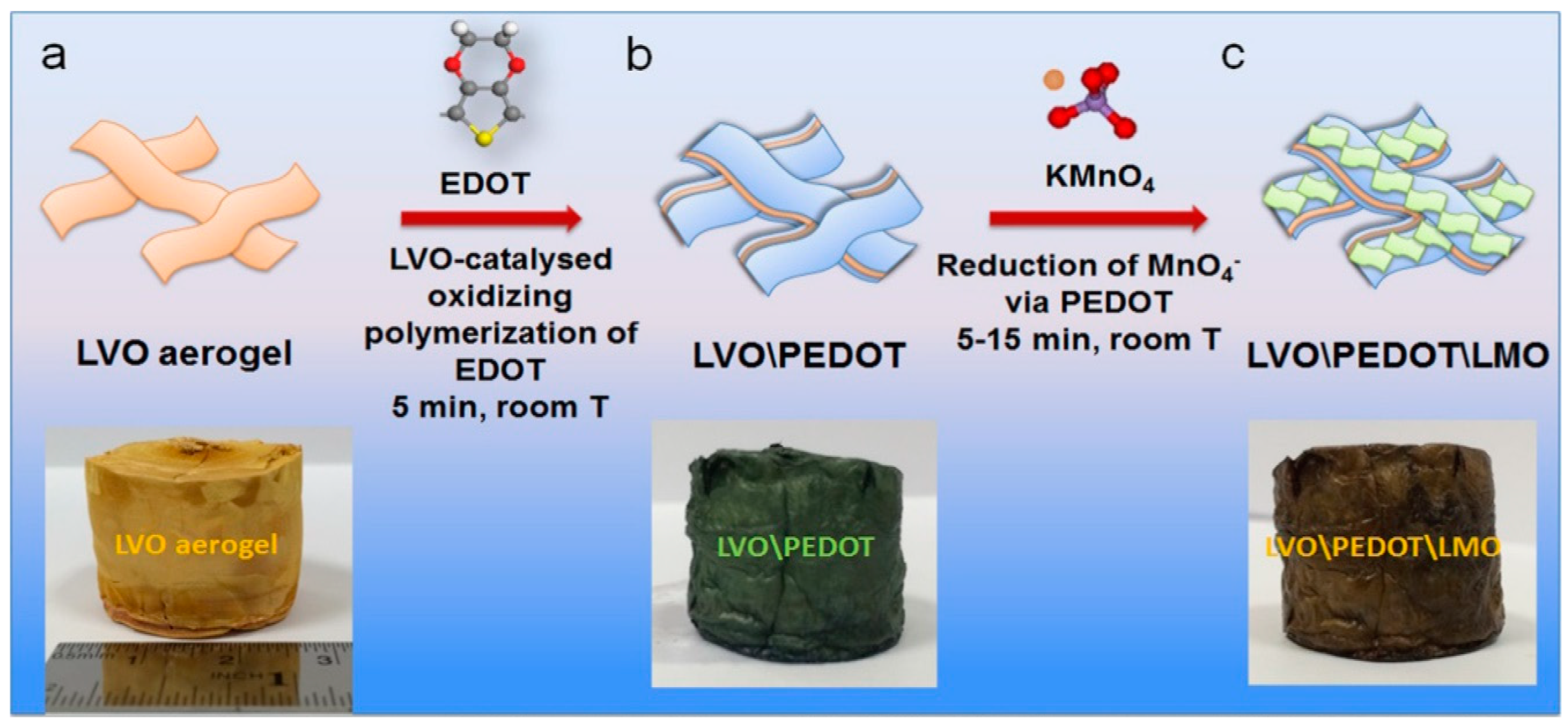
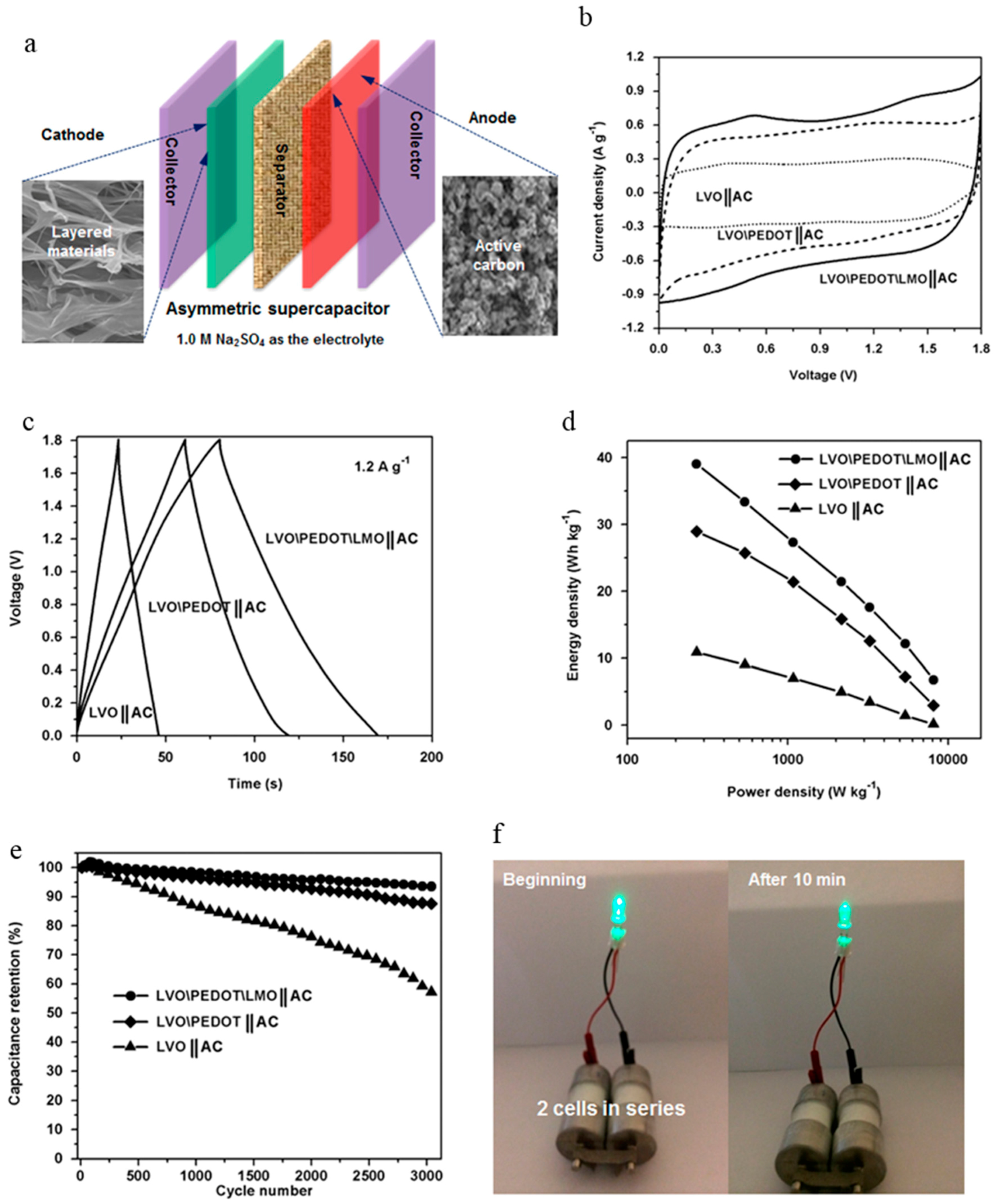
- Guo, C.X.; Yilmaz, G.; Chen, S.; Chen, S.; Lu, X. Hierarchical nanocomposite composed of layered V2O5/PEDOT/MnO2 nanosheets for high-performance asymmetric supercapacitors. Nano Energy 2015, 12, 76–87. [Google Scholar] [CrossRef]


| Material | Csp | E | P | Stability | Electrolyte | Ref. |
|---|---|---|---|---|---|---|
| PEDOT/PNMPY/PEDOT | 90 F·g−1 at 100 mV·s−1 | - | - | - | 0.1 M LiClO4 | [82] |
| Multilayered PANI | polypropylene | [114] | ||||
| Potentiodynamic | 468 F·g−1 at 50 mV·s−1 278 F·g−1 at 3 mA cm−2 | 24.4 Wh·g−1 | 0.08 W·g−1 | 93.5% over 500 cycles | - | - |
| Potentiostatic | 12 F·g−1 at 50 mV·s−1 0.08 F·g−1 at mA cm−2 | 0.027 Wh·g−1 | 0.16 W·g−1 | - | ||
| Galvanostatic | 15 F·g−1 at 50 mV·s−1 0.03 F·g−1 at 3 mA cm−2 | 0.013 Wh·g−1 | 0.56 W·g−1 | - | ||
| PEDOT/PPy/PEDOT | 150 F·g−1 at 20 mV·s−1 | 15.7 Wh·kg−1 | 2136. W·kg−1 | 14% over 1000 cycles | 0.1 M LiClO4 | [123] |
| Material | Csp | E | P | Stability | Electrolyte | Ref. |
|---|---|---|---|---|---|---|
| ♣ PANI/GO multilayer | 504 F·g−1 at 10 mV·s−1 429 F·g−1 at 1 mA | - | - | 82% over 1000 cycles | 1.0 M H2SO4 | [100] |
| ♣ PANI/GO multilayer | 375.2 F·g−1 at 0.5 A·g−1 | - | - | 90.7% over 500 cycles | 1.0 M H2SO4 | [125] |
| ♣ PANI/rGO on ITO | 529 F·cm−3 at 3 A·cm−3 | - | - | 86% over 1000 cycles | 1.0 M H2SO4 | [126] |
| ♣ PANI/rGO on PET | 956 F·cm−3 at 3 A·cm−3 | 79% over 1000 cycles | ||||
| ♣ PANI/rGO | 584 F·cm−3 at 3 A·cm−3 | - | - | 56.5% over 1000 cycles | 1.0 M Na2SO4 | [61] |
| rGO/PANI | 916 F·g−1 at 5 mV·s−1 | 127.9 Wh·kg−1 | - | 86% over 1000 cycles | 6.0 M KOH | [127] |
| PPy/rGO | 315 F·g−1 at 10 mV·s−1 | ~100 Wh·kg−1 | ~1.5 kW·kg−1 | ~88–90% over 1000 cycles | 1.0 M H2SO4 | [128] |
| PANI/rGO | 390 F·g−1 at 10 mV·s−1 | |||||
| PANI/rGO | 250 F·g−1 at 10 mV·s−1 | |||||
| GO/(PPy)3 | 332 F·g−1 at 5 mV·s−1 341 F·g−1 at 2 mA·cm−1 | 78 Wh·kg−1 | 6 W·kg−1 | - | 1.0 M H2SO4 | [78] |
| ♣ PPy/fiber GO | 510 F·g−1 at 0.3 A·g−1 | - | - | - | 2.0 M H2SO4 | [130] |
| ♣ PPy/sphere GO | 528 F·g−1 at 0.3 A·g−1 | - | - | - | ||
| ♣ rGO/PANI nanofiber | 5.16 F·cm−2 at 10 mA·cm−3 3.35 F·cm−2 at 10 mV·s−1 | - | - | 93% over 1000 cycles | 1.0 M H2SO4 | [134] |
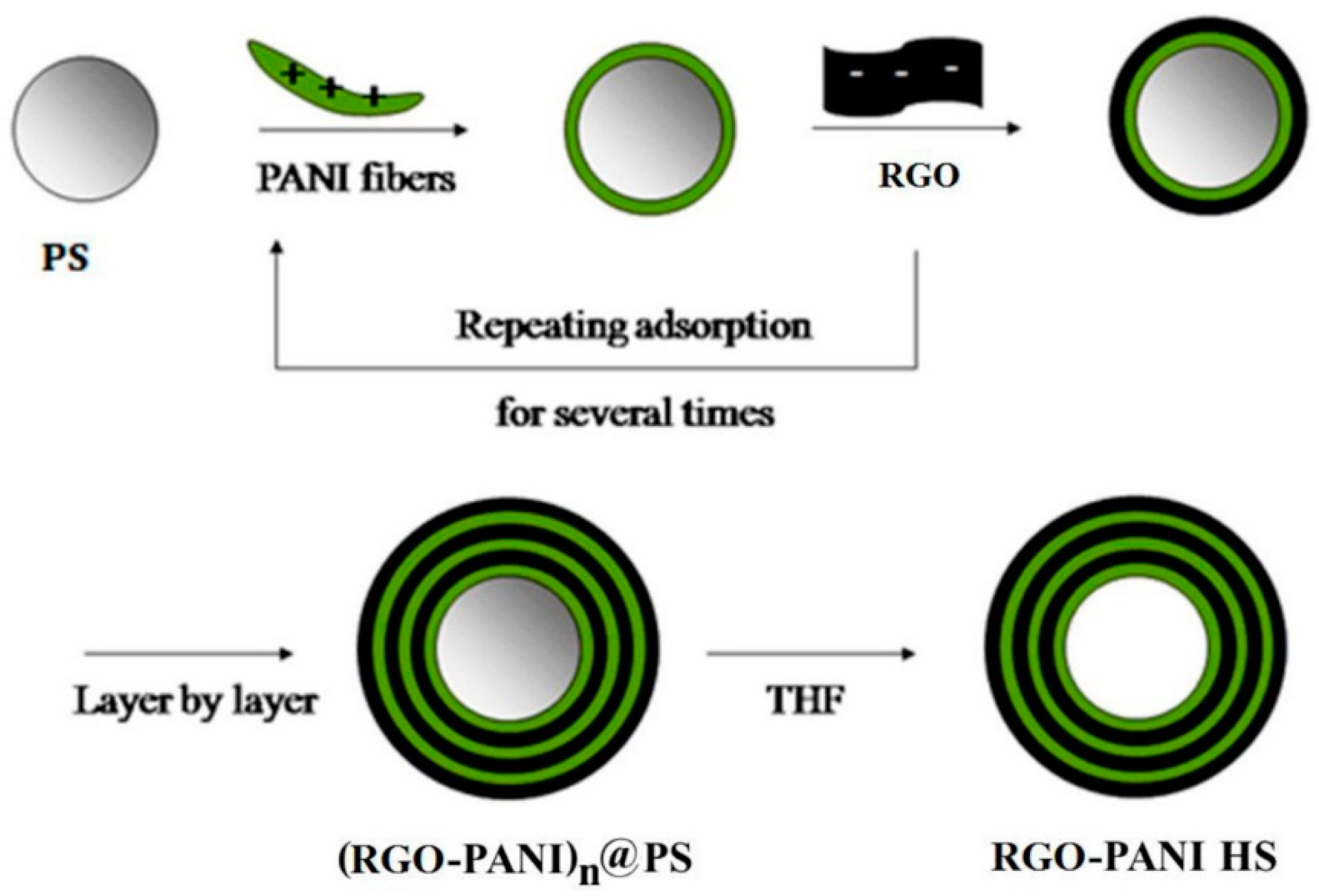
| ♣ rGO-PANI hollow spheres | 456 F·g−1 at 0.5 A·g−1 | - | - | 83% over 1000 cycles | 1.0 M H2SO4 | [76] |
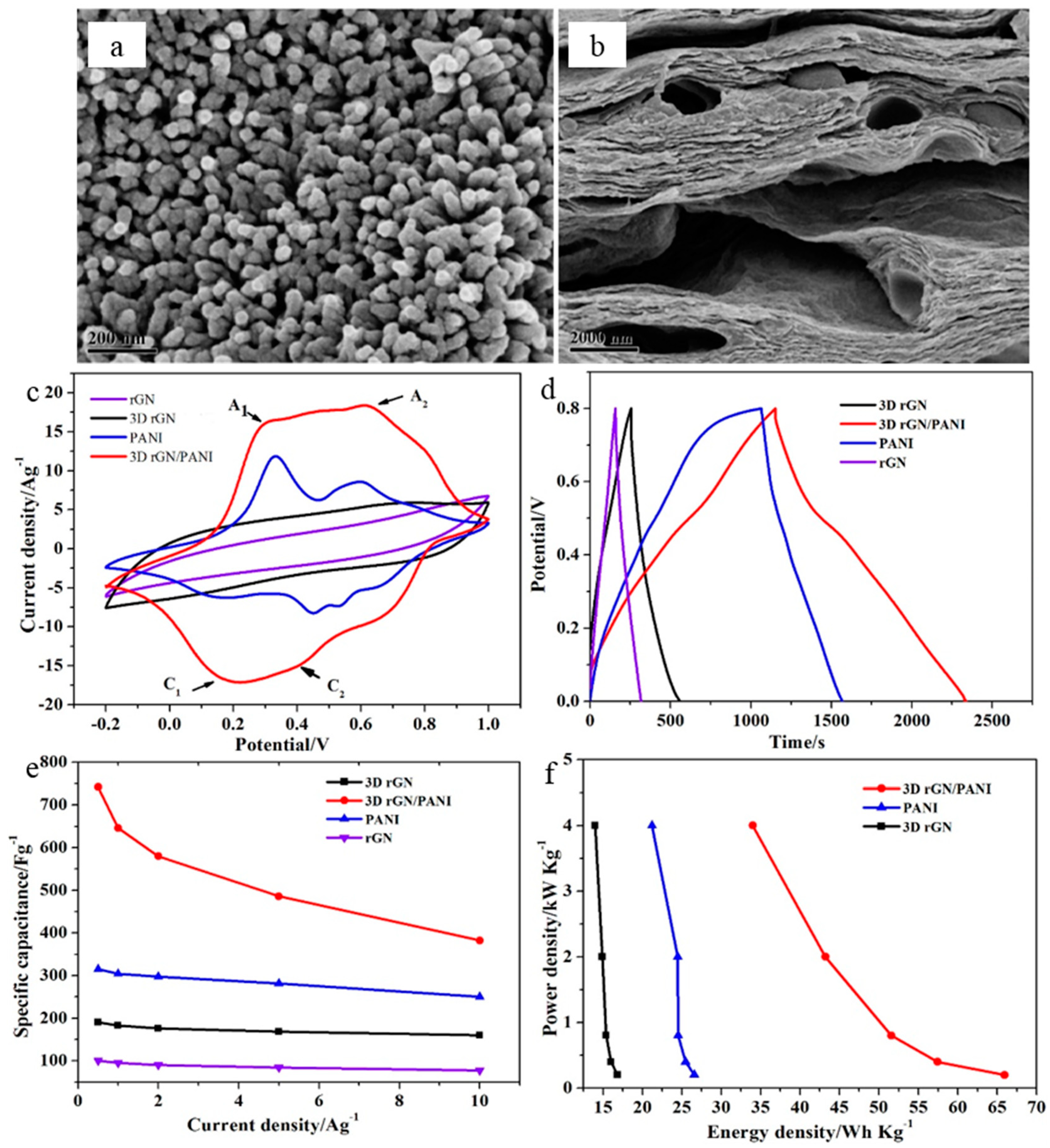
| ♣ 3D rGO/PANI | 740 F·g−1 at 0.5 A·g−1 | 65.94 Wh·kg−1 | 4 kW·kg−1 | 87% over 1000 cycles | 1.0 M H2SO4 | [136] |
| 3D rGO/PANI | 401.5 F·g−1 at 4 A·g−1 | - | - | 76.5% over 2000 cycles | 1.0 M H2SO4 | [137] |
| rGO/PANI nanowire | 790 F·g−1 at 1 A·g−1 | 17.6 Wh·kg−1 | 98 kW·kg−1 | 80% over 5000 cycles | 1.0 M H2SO4 | [139] |
| Material | Csp | E | P | Stability | Electrolyte | Ref. |
|---|---|---|---|---|---|---|
| PEDOT/RuO2 | 420 F·g−1 | 27.5 Wh·kg−1 | - | - | 0.5 M H2SO4 | [141] |
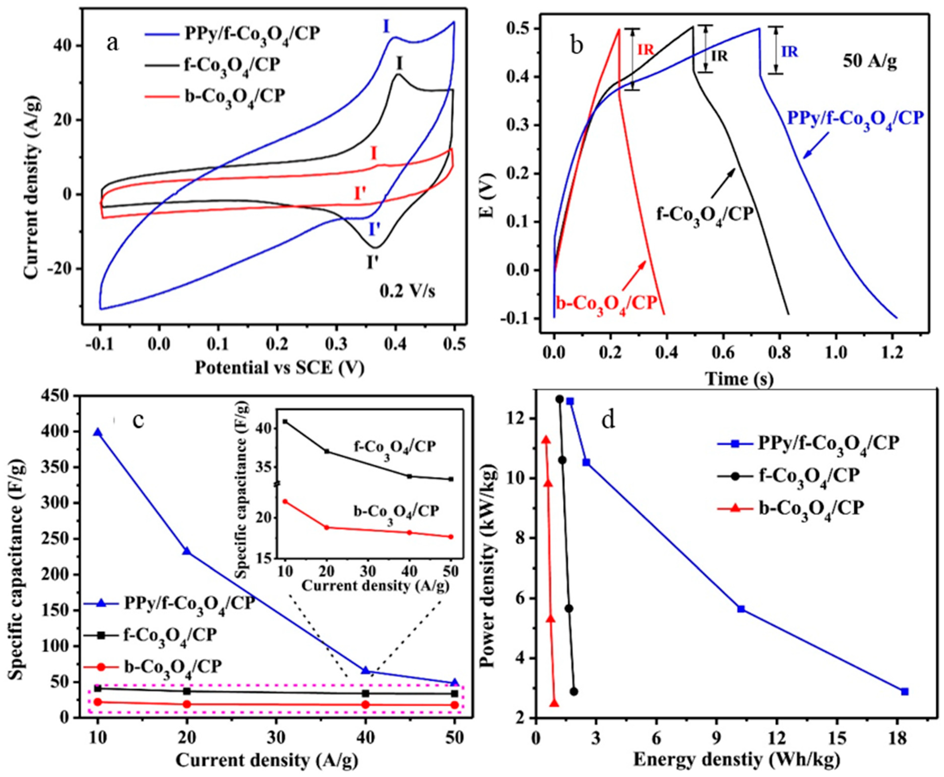
| PPy/Co3O4 | 398.4 F·g−1 at 10 A·g−1 | 8.4 Wh·kg−1 | 2.9 kW·kg−1 | 100% over 1000 cycles | 2.0 M KOH | [145] |
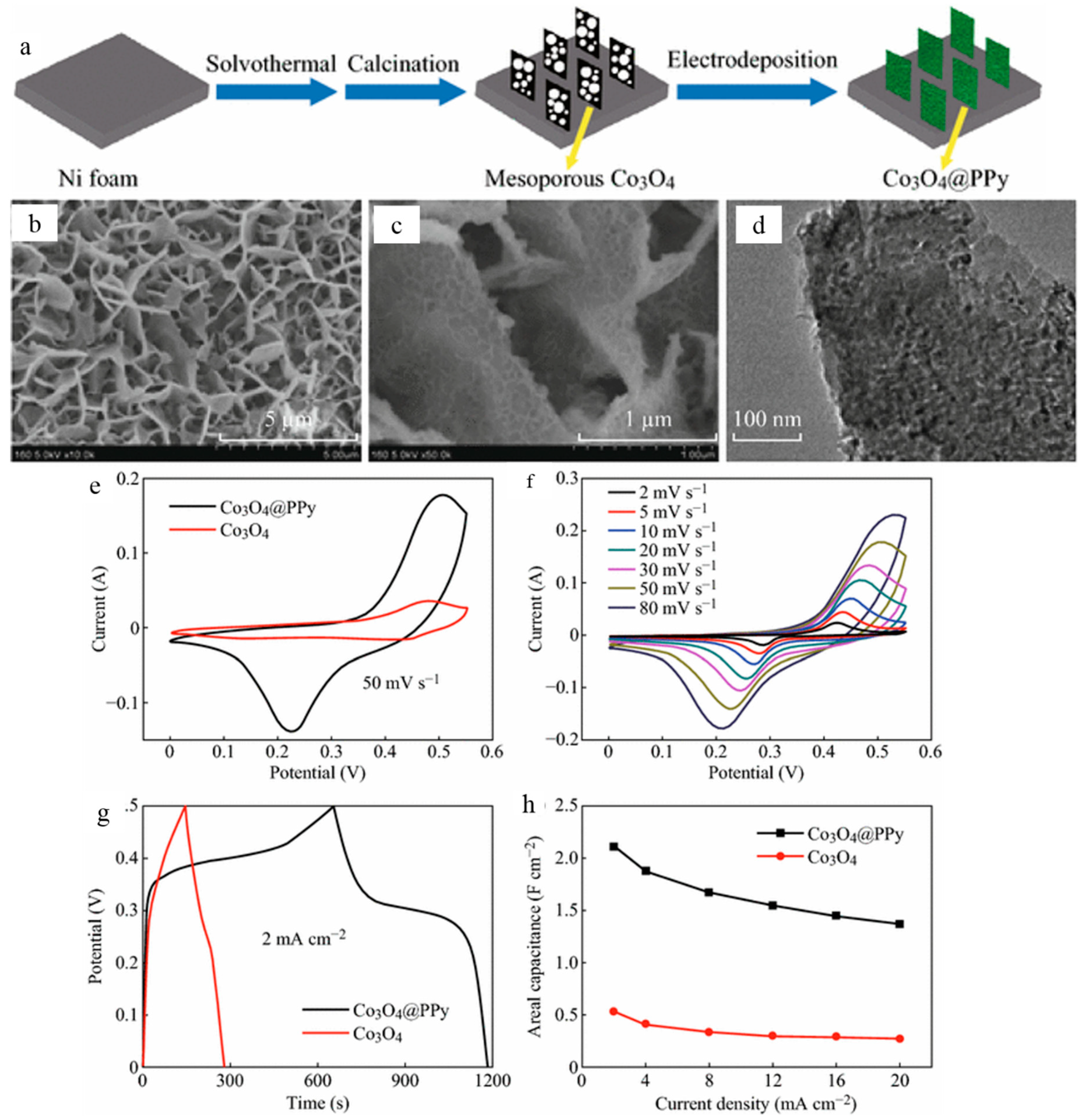
| ♣ PPy/Co3O4 nanosheet | 2.11 F·cm−2 at 2 mA·cm−2 | - | - | 85.5% over 5000 cycles | 1.0 M KOH | [147] |
| V2O5/PEDOT/MnO2 | 85.7 F·g−1 at 0.5 mV·s−1 | 21.7 Wh·kg−1 | 2.2 kW·kg−1 | 93.5% over 3000 cycles | 1.0 M Na2SO4 | [148] |
© 2019 by the authors. Licensee MDPI, Basel, Switzerland. This article is an open access article distributed under the terms and conditions of the Creative Commons Attribution (CC BY) license (http://creativecommons.org/licenses/by/4.0/).
Share and Cite
Kulandaivalu, S.; Sulaiman, Y. Recent Advances in Layer-by-Layer Assembled Conducting Polymer Based Composites for Supercapacitors. Energies 2019, 12, 2107. https://doi.org/10.3390/en12112107
Kulandaivalu S, Sulaiman Y. Recent Advances in Layer-by-Layer Assembled Conducting Polymer Based Composites for Supercapacitors. Energies. 2019; 12(11):2107. https://doi.org/10.3390/en12112107
Chicago/Turabian StyleKulandaivalu, Shalini, and Yusran Sulaiman. 2019. "Recent Advances in Layer-by-Layer Assembled Conducting Polymer Based Composites for Supercapacitors" Energies 12, no. 11: 2107. https://doi.org/10.3390/en12112107