Article

PMSG-Based Black-Start Technology and Its Field Tests

1
College of Automation Engineering, Nanjing University of Aeronautics and Astronautics, Nanjing 211106, China
2
School of Electrical Engineering, Southeast University, Nanjing 210096, China
*
Author to whom correspondence should be addressed.
Energies 2019, 12(11), 2144; https://doi.org/10.3390/en12112144
Submission received: 9 April 2019 / Revised: 30 May 2019 / Accepted: 31 May 2019 / Published: 4 June 2019
(This article belongs to the Special Issue Control Schemes for Wind Electricity Systems)

Abstract

:
It is of great importance for power grids to have black-start capability for rapid recovery, and there is great theoretical significance and practical application value in studying how to use wind farms as the black-start power supply source for power grids with large-scale renewable energy generation. In this paper, a black-start scheme using a permanent-magnet synchronous generator (PMSG)-based wind farm as black-start power supply source is formulated. First, a diesel generator is used as an external supporting power supply for the self-start of a wind power unit (WPU). Then, after all the planned WPUs operate normally, the wind farm with the diesel generator and static var generator (SVG) is used to black start the simulated auxiliary load of a thermal power plant. A field test of the proposed black-start scheme is carried out on an actual wind farm in Jiangsu Province (China). The results of the field test show that wind farms can act as a black-start power supply source for the grid after appropriate technological transformation.

1. Introduction

With the rapid development of UHV AC and DC transmission, large-scale grid-connected renewable energy generation and communication technologies, the possibility of power grid blackouts is increasing due to uncertainty of renewable energy generation, cascading failures and cyber-attacks [1,2]. It is of great significance to develop reasonable black-start schemes for power grids with large-scale renewable energy generation.
Benefiting from the advantages such as faster start-up and lower energy requirements, hydroelectric and combustion gas turbines are often the primary choices of traditional black-start power supply sources. At the same time, hydroelectric power availability is limited by geographical conditions and seasonal factors, and the operation and maintenance costs of the combustion gas turbines are extremely high. Therefore, there is an urgent requirement to find new forms of energy to support the black start of power grids [3,4,5].
China has built large numbers of wind farms along the northwestern, northeastern, northern and eastern coasts. The penetration rate of wind power is increasing year by year. The capacity of wind power generation in China reached 188,390 MW in 2017. More importantly, the distribution of wind power is extremely broad, and covers 31 provinces in China. The spatial distribution, seasonal difference and potential black-start supporting ability makes it an effective supplement for hydroelectric power sources [5,6,7,8].
Scholars from all over the world have conducted many research studies on this topic [9]. A new wind turbine structure that can be applied for black starts has been proposed by a Chinese professor from the Huazhong University for Technology and Science [2]. Aktarujjaman et al., from Australia, have proposed a new method and its control system, which can be used to black start a double-fed induction generator (DFIG) [6]. The North China Electric Power Research Institute attempted to launch a black-start field test using the National Scenery Storage Demonstration Power Station [10]. In general, the current achievements in this field include: (1) the self-start ability of wind turbine based on external power supply [10,11,12]; (2) the decision making and effect evaluation of black-start scheme for wind farms [13,14,15,16,17]; (3) the voltage and frequency issues that occurred in wind farms during black start process [18,19,20].
Studies have shown that the following problems should be considered when using wind farms as a black start power supply source: (1) the contradiction between the fluctuating nature of wind power and the high stability requirement of black-start power source [21,22]; (2) the rationality of external power supply configuration [23,24]; (3) the influence on wind turbine body and its isolation system caused by the severe attack of grid-connected power components during black start process [25,26]; (4) the black-start transformation requirements for wind turbine structure, control strategy and wind farm system [2,10,27,28].
There is much research in the field of black-start practice involving wind farms. Sun built a wind farm model and simulated the three stages of a black start of the power grid [2]. The results showed that wind farm participation in a black start is feasible. In order to increase load and minimize interruption time, Bizon studied the possibility of insertion of wind power plants in the hydroelectric plants corridors with black-start capacity [7]; El-Zonkoly proposed a firefly algorithm to find the optimal final sequence of non-black start units restoration, transmission paths and load pick-up sequence [29]; Golshani developed a novel offline restoration planning tool for harnessing wind energy to enhance the resilience of power grid [1]. Based on the National Wind Storage Demonstration Power Station, a wind farm was used as a black-start power supply, and the reasons for the failure of the self-start of the wind turbine in this test were analyzed [10]. A black start test was carried out successfully by the State Grid Jibei Electric Power Co., Ltd. at the above power station [30]. Through a simulation analysis of the wind farm and thermal power plant data under an actual substation, it has been used as a good reference for the black-start application of wind farms [8]. A black start test using wind power generation and diesel generator was completed in Jiangsu Province of China [31].
Based on the current theoretical and practical research status of wind farms as black-start power sources at home and abroad [29,32,33,34,35], there is no technical plan that involves a field test of wind farms as a black start power source in an actual power grid. To verify the black-start capability of the wind farm and promote its engineering applications, this paper proposes a black-start scheme based on a PMSG-based wind farm as power source: first, the diesel generator is used as an external supporting power supply for the self-start of a WPU, and after all planned WPUs are running normally, the wind farm with the diesel generator and the SVG is used to black start the simulated auxiliary load in a thermal power plant. Then, the field test of the scheme is realized on an actual wind farm in Jiangsu Province in China, and the detailed test process is analyzed.

2. Black-Start Scheme

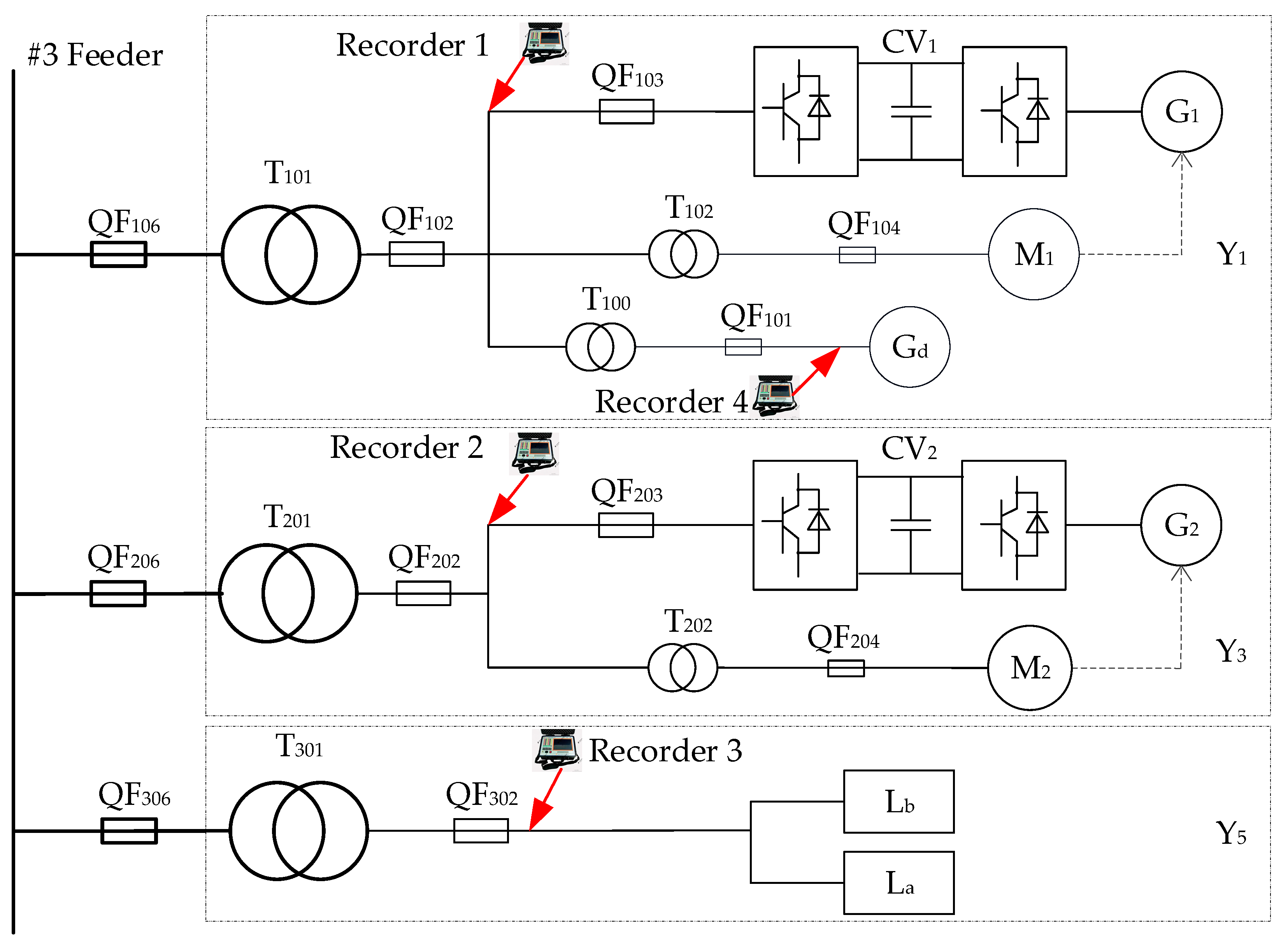
2.1. Situation on Site

Figure 1 shows the topology of a wind farm in Jiangsu. The installed capacity of the wind farm is 100 MW, and there are three collection lines equipped with 50 PMSG-based WPUs with a rated capacity of 2 MW. In addition, there is an SVG with a rated capacity of 0.5 MVar. The electrical distance from a near thermal power plant to the wind farm is 30 kilometers. The installed capacity of the thermal power plant is 9 MW, and the maximum auxiliary power of the single unit in the thermal plant is 300 kW.
Figure 2 shows the electrical topology of the PMSG-based WPU in the wind farm. The cut-in and cut-out wind speeds are 2.5 m/s and 18 m/s, respectively. The cabin load of the WPU is powered by a 400 V power supply, and the maximum instantaneous power of a single WPU load is approximately 50 kVA. The PMSG is connected to the box transformer through a back-to-back full-power converter for power output.
According to the investigation of the site topology, geographical conditions and communication network, the three WPUs connected to collector line 3, Y1, Y3 and Y5, were selected for testing, and the total length of the power line was 8.5 kilometers.

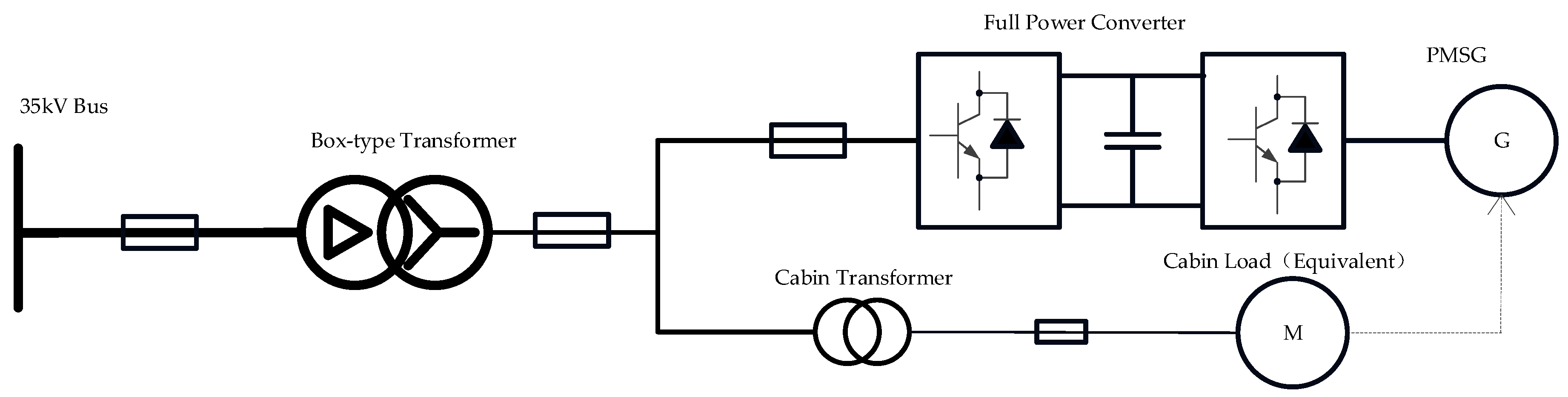
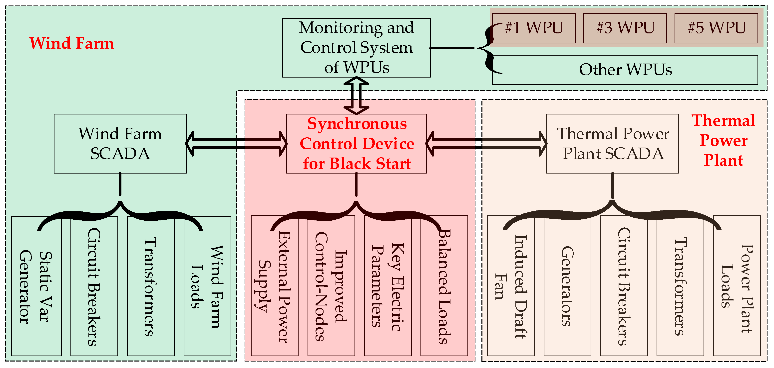
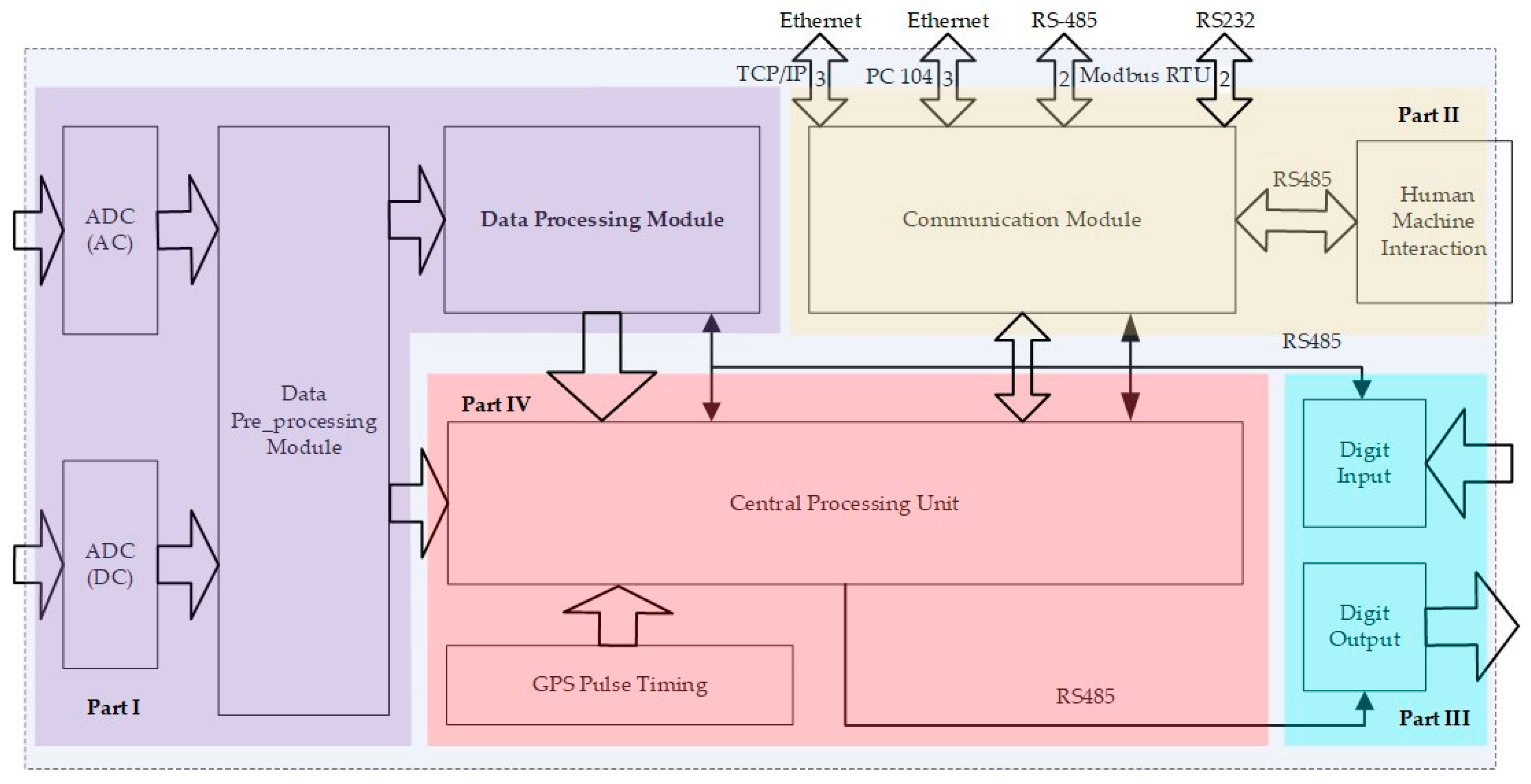
2.2. Black-Start System

For black start testing, an external power supply, some balanced loads and a black start target are needed. It is necessary to carry out the corresponding transformations and increase the measuring equipment. The field test system diagram for the black start is shown in Figure 3.
The equipment used in the black-start system is listed in Table 1. The diesel generator, shown as Gd, is used as an external power supply. The minimum power output of a WPU is 300 kW, which cannot be completely consumed by the equivalent load of the wind turbine, shown as M2, in Figure 3, and the remainder needs to be consumed by the balanced load shown as Lb, which is an electronic load composed of resistors, inductors and capacitors. However, the Lb should be powered by Gd before the WPU operates normally. Considering the active and reactive power characteristics of the WPU, this paper selects the capacity of the diesel generator as 400 kVA, of which 100 kVA is reserved for safety. For the same reason, the power of the balanced load is 1000 kVA. The maximum auxiliary power of a single thermal power plant is 300 kW. Taking the impactful power into account, the instantaneous power of the simulated auxiliary load of the thermal power plant, shown as La, is 3000 kVA.
From Figure 1, Figure 2 and Figure 3, the adjustments are as follows: (1) on the low voltage busbar of the box-type transformer, shown as T101, Gd is connected through a step-up transformer, shown as T100; (2) the removal of all equipment on the low-voltage busbar of the box-type transformer that belongs to Y5, where La and Lb are connected in parallel; (3) the oscilloscopes are installed at the outlet of the grid side of Y1 and Y3, and at the access point of La, Lb, and Gd.
In order to synchronize the steps, a synchronous control device for black start (SCDBS) is developed, and the relationship of the logic is shown in Figure 4. The equipment in the green block belongs to the wind farm, the SCADA is used to monitor the parameters of transformers, circuit breakers, loads and SVG. Then, the above parameters are sent to SCDBS, where the monitoring and control system of WPUs is. The equipment of the thermal power plant is shown in the light-yellow block, and the SCADA here plays the same role as it does in the wind farm. The equipment in the red block is added through an abovementioned transformation for the purpose of changing the normal grid structure to a black start system.
SCDBS is the central controller of the system, which a black start strategy is embedded in. After the operating information of the whole system is collected, a series of black start operations will be automatically executed according to the above strategy. The implementation of the device and strategy are described in detail below.
The hardware framework of SCDBS is presented in Figure 5. There are four types of interfaces for interacting with external devices and users. Part I is a data acquisition and processing module, which adopts FPGA to control the AD converter and transforms analog quantities into digital quantities. The real time value of voltage, current frequency, phase difference, active and reactive power can be measured. Part II is designed to communicate with the external devices and users. There are three kinds of communication ports, six Ethernet ports with TCP/IP and PC 104 protocol, three RS-485 port and two RS-232 port with Modbus RTU. The Ethernet ports are used for the communication between SCDBS and SCADAs, monitoring and controlling systems in wind farms and thermal power plant. The remaining Ethernet, RS-485 and RS-232 ports are reserved for external power supply, balanced loads and improved control-nodes. In addition, there is a human machine interaction, the running state, the key parameters and the interface of control instruction are displayed on an LCD screen. The black start operations can be manually performed by user. Part III is a digit input and output module, which monitors the states of circuit breakers and operates them according to the instructions. Part IV is the central processing unit, where a black start strategy is implemented, and a GPS pulse timing is used to synchronize with the system clock. All the above information will be sent to the central processing unit, and then the black start strategy determines the next execution based on the current steps and the obtained information.
Figure 6 shows the control strategy of SCDBS, it is a general strategy for any step (such as step N) in the black start process. After the program starts, all the running parameters will be initialized, N is the current step number, Nmax is the last step number of the test. Then, the program performs the corresponding judgment according to the value of N, if the current condition meets the requirements for performing step N, the operation will be executed; and a delay is executed if some parameters or states beyond the range set at step N. After the delay, the step N is performed if the condition meets the expected one, otherwise the program will go back to initialization and display the corresponding fault code. Following this process, the program is finally executed to step Nmax, all prompt message will be displayed on the LCD screen in the whole process. In conjunction with Figure 7, the judgment criteria in every main step will be introduced in detail.

2.3. Black-Start Scheme

The proposed black-start scheme consists of eight steps in three stages. (1) For the purpose of a systematic experimental topology and the follow-up data analysis, transformation stage of black-start system is necessary: (A) the topology of power grid should be adjusted, the equipment including generators and loads should be installed, and the measuring instrument needs to be debugged; (2) Since the wind power is acted as a power source in the black start, the self-starting stage of wind farm is essential: (B) the charging of the primary equipment is the first step for the self-start of the WPU because of the existence of preheating, dehumidification and mechanical transmission; (C) then, Lb is energized to avoid the reverse power flowing to Gd; (D) Y1 is Started after the isolated system is running normally, (E) Y3 is started at the same condition with Y1, the both self-start progress are recorded; (F) for the sake of stability, the capacity of the system is increased; (3) due to the complicated process, black starting the target load is the last but most important stage: (G) under almost consistent initial conditions, the simulated auxiliary load with different power value is black started in three trials respectively, (H) for the experiment, the system should be split after La is black started:
 (A) Equipment installation and system debugging
In this step, the operation mode adjustment for the black-start system in the wind farm is carried out: the collector line 3 is in cold stand-by, the high voltage side of all WPUs are disconnected from collector line 3 and the low voltage circuit breakers are in the open state. After connecting all the devices listed in Table 1, the monitoring power supply, the voltage source and the current source are turned on to ensure the normal operation of the monitoring equipment. The system topology after the completion of debugging is shown in Figure 7a.
 (B) Charging for the primary equipment
Before the diesel starts, all the circuit breakers QF101, QF102, QF106, QF206, QF202 and QF306 must be closed. To avoid the circuit breaker tripping or system collapse caused by the magnetizing inrush current of a transformer or charging line, Gd is stepped up from zero in this test. In the process of Gd’s terminal voltage rising from 0 to the rated voltage, the voltage of the transformer and the line also reach their respective rated values. As shown in Figure 7b, while the line is red, it is indicating that the line is energized.
 (C) Powering Lb
If the system frequency, the voltage of the transformer and the line reach their respective rated values at this step, circuit breaker QF302 is closed, and then the active power of Lb is gradually increased to 400 kW from 0 at a rate of 10 kW/2 s. At this point, a balancing system with Gd, the transmission line, the transformers and Lb is formed, which is presented in Figure 7c.
 (D) Starting Y1
Similar to the previous step, if the frequency and voltage of each node of the system are operating in the allowable range set at this step, the wind condition is acceptable, and there is no fault reported by the SCADA in wind farm. Circuit breaker QF104 for M1 is closed, and then M1 is energized. Y1 is ready to provide electricity while the “START” command has arrived. Then a start command from SCDBS is sent to Y1, which begins startup and runs at maximum output power at 300 kW. A new balancing system containing one WPU is formed, as shown in Figure 7d.
 (E) Starting Y3
On the basis of normal operation of the above system, the active power of Lb is increased to 800 kW in the same way as step (C). If all parameters such as the system voltage and frequency, the output power of Y1, the temperatures of the equipment in the whole system are normal, Y3 is started in the same way in step (D). A new balancing system involving two WPUs is formed, as presented in Figure 7e.
 (F) Increasing the capacity of the system
The whole capacity of the isolated system in step (E) is approximately 800 kW, and Gd runs in power output mode. For the purpose of providing sufficient voltage and frequency support by Gd during the black-start process, the output power of Y1 is adjusted to 300 kW, and the output power of Y3 should be adjusted manually to satisfy that the output power of Gd is close to 0. The above process is executed by SCDBS and monitoring and control system in wind farm.
 (G) Black starting La
The power of La is 0 at a relative time of zero, and the new output limit of the Y1 unit is increased to the rated value of the simulated load in the thermal power plant based on the original operating conditions. When t = 10 s, La is energized, and Lb is gradually removed according to the power shortage. If the system voltage or frequency is high, the inductance or resistance of Lb will be increased; and the inductance or resistance of Lb will be reduced if there is a low system voltage or frequency. The voltage, frequency and power of Gd, Y1, Y3, La and Lb are recorded, the system topology is shown in Figure 7f.
 (H) Splitting the system
After La is black started, Y1 is stopped first, then the power of La is decreased slowly to 0. In the same fashion, Y3 is stopped and Lb is removed. Finally, Gd is shut down, the system topology is set to the normal operation mode.

3. Analysis of the Test Results

Based on the data from the WPU operation log and the recorder, the Lb access, self-start of WPU Y1 and Y3, the black start of the La, and the splitting process are analyzed during the field test.

3.1. Lb Access

Lb is used to consume the power of the isolated system. Its switching purpose is to maintain the system stability for voltage and frequency and to prevent the reverse power operation of Gd. Before starting WPU Y1 and Y3, it is necessary to create a load in advance, and Lb is divided into two parts considering the capacity of Gd and fuel consumption.
The processes of increasing the Lb from 0 to 400 kW is set before self-starting any WPU, and the processes of increasing the Lb from 400 kW to 800 kW is set after self-starting Y1. The rate of increase during the Lb power increase step is 10 kW every two seconds. The main parameters when Lb is connecting are listed in Table 2. The actual measured power of Lb after the two inputs are 340 kW and 984 kW, which are lower or higher than the expected value. As shown in Table 2, both voltage fluctuation and frequency fluctuation are much severer than the first time.
As shown in Figure 8, Lb is gradually increased from 400 to 800 kW before Y3 is self-started. There is an obvious voltage and frequency fluctuation in the system while Lb is increasing and the fluctuation intervals of frequency, voltage, active and reactive power are all larger before and after Lb is increased.
Lb consists of resistance, inductance and capacitor, and Ohm’s law is followed by the algorithm of power control system of load bank. The values of Lb are set based on the initial voltage, frequency and the target power. In the process of Lb is increased, the voltage and frequency are also fluctuating. In other words, the impedance of Lb is constant; the voltage and frequency are time variable; the power of Lb will be changed based on Ohm’s law.
In the first processes of increasing Lb, Gd only supplies power to Lb, which is small at that time. But in the second processes, Gd not only supplies power to Lb, which is much bigger than before, but also provides voltage and frequency support for Y1. More seriously, Y1 is set to limited power operation mode, and its output power is fluctuating when the wind speed is low, the load increment is undertaken by Gd. That’s to say, when the power consumption of Lb is set to 400 kW and 800 kW respectively, the output power of Gd may be both large than 400 kW. As a result, the stability of the voltage and frequency exceeds the upper limit of Gd, which may be the cause of system fluctuation. The power shortage is obviously bigger the second time, so the system fluctuation is significantly severer than it is at the first time.
The above two problems are caused by a shortage of power supply in the system that provides the support of power, voltage and frequency. There are three solutions to the problem: the most direct and effective way is to configure an external power supply with a larger rated capacity; the most economical and practical way is to choose a wind farm with a larger annual average wind speed as a black start power plant to increase the output power and stability of the wind turbine; and the best way is to develop a wind turbine with the ability to maintain the stability of voltage and frequency.
At the same time, the maximum value of the fluctuation is also related to the input load power. To improve the stability of the system, the single load with a large power should be energized in the initial stage, and then the loads with small power can be connected.

3.2. WPU Self-Starting

At this stage, the failure of the WPU to start and to suddenly stop running after a successful startup both occurred. Shown in Table 3 is the main parameter list for six WPU startup tests. No. 1 and No. 2 are the self-starting process of Y1, No. 3 to No. 6 are the self-starting process of Y3. After taking 11 seconds, 83 seconds and 32 seconds, respectively, the self-starting processes at No. 1, No. 2 and No. 6 are successful. At a wind speed greater than 2.5 m/s, Y3 is started four times and failed for the first three times, and a grid side voltage abnormality fault is reported.
There is a continuous voltage higher than 818 V in the processes of No. 3 to No. 5. When the power factor of Lb is adjusted to 0.8, and the initial voltage on the grid side is reduced to approximately 670 V, Y3 self-started when the wind speed was 3.65 m/s. The waveforms of frequency, voltage, active and reactive power are shown in Figure 9, and the fluctuation range of the main electrical parameters during the self-starting process is shown for No. 6 in Table 3. In all successful trials, the maximum frequency and voltage fluctuation value are 7.24% and 2.25%.
Benefitting from consulting the WPU operating manual, it is learned that the grid-connected protection of the WPU will be triggered when the grid side voltage continues to be higher than 110% of the rated value for 2 s, the grid side voltage continues to be higher than 115% of the rated value for 0.5 s, or the grid side frequency fluctuation continue to be greater than 105% for 2 s.
After a comprehensive analysis of the WPU operating manual, the recorded data and the operating log of the WPUs, the reasons why the WPU failed to self-start or stop running are found. The first three Y3 startup attempts failed due to the internal reported failure. Y1 is turned off after it is started in grid-connected mode since the wind speed is less than the cut-in requirement for an extended period. The failure of No.3 and No.5 are caused by high voltage, test No. 4 failed for both high voltage and low frequency. The high voltage recorded during the Y3 startup process is caused by the capacitive effect of the 8.5 km feeder for the wind farm.
From the three successful tests, it can be found that within the cut-in and cut-out wind speed range, the higher the wind speed, the faster the WPU start-up process. Besides, the start-up time has a nonlinear relationship with the wind speed; and the startup process of the WPU is affected by the fixed value of the grid-connected protection.
By summarizing and analyzing the startup process of the above six tests, the following solutions can be used to speed up the self-start process or reduce the possibility of failure. Firstly, it is essential to choose a wind farm with a large and stable annual average wind speed when selecting a black start power plant. Secondly, the self-start process may be affected by the WPU protection settings, so it should be calculated precisely and adjusted as needed before the actual black start. Thirdly, in the case of a small system capacity, a long transmission line will increase the stability of the system voltage but affect the startup process of the WPU, and its negative impact can be reduced by connecting an SVG to the isolated system.

3.3. Black Starting La

After the normal operation of the WPUs, three on-site black-start simulation tests have been carried out, and the power used in each experiment are 100, 200 and 300 kW, respectively. Before each La input, the output power of Y1 is adjusted so that the output active power value of Gd is approximately 200 kW. During the black-start process, the power is regulated by Y1, Y3 is always running in 500 kW limited power mode.
Table 4 shows the main electrical parameters of the system when 100, 200 and 300 kW simulated auxiliary loads are black-started under the same initial conditions. To meet the power demand of La quickly, the preadjusted power value of Y1 is greater than the value of La to be started.
The process for the WPU output power occurs after the action of the mechanical parts such as yaw and pitch, usually takes a few seconds. Therefore, it is necessary to adjust the power change value according to the actual response speed of the wind turbine before black starting the thermal power plant simulation auxiliary machine. On the basis of checking the power change response of the wind turbine and the self-starting of the wind farm, the coordinated control process of the wind farm participating in the black start is as follows: (1) the program running in the control device for the wind farm black start is initialized; (2) an output power adjustment value to the WPU monitoring system is sent by the abovementioned device; (3) the wind farm black-start device starts counting down after receiving the correct information from the wind turbine monitoring feedback; (4) a load input command is sent to the monitoring system for the auxiliary machine in the thermal power plant by the above device after receiving the response of the wind turbine and the countdown is over.
As shown in Figure 10, the initial voltage of the system is 690 V, the power limit of Y1 has been changed for 5 seconds before putting La into the power system, and the black-start process is performed on an auxiliary load of 100 kW. The black start duration is about 2.3 seconds, the output power change of Y1 takes 7.5 seconds, and the changed power is about 250 kW.
At the beginning of black start, the voltage, frequency and output power of Ld have experienced a short-term fluctuation. It is worth noting that the amplitude of the grid side voltage is less than the protection value of 621 V, and it lasts for approximately two cycles. Gd has a reverse power of 5 kilowatts which last about 5 milliseconds, the maximum and minimum frequency in the black-start process are 52.1 Hz and 48.4 Hz, respectively. The output power of Y1 lag behind the power consumption of La, the power consumption of La is almost supplied by Gd.
Because of the extremely transient fluctuation time, neither Y1 nor Gd are off-grid. And the reverse power of Gd can be reduced by adjusting the output power and presetting time of Y1. To prevent the falling voltage of the system from exceeding the protection value during the black-start process, the initial voltage can be preset higher. And the longer preset time of Y1 can make a contribution to the power supply of Gd during La is black started.
Before starting the second test, the initial voltage is raised to 710 V, the presetting time of Y1 has been changed to 8 s. As shown in Figure 11, it is the black-start process when La is 200 kW. The voltage and frequency fluctuations have improved compared to the first attempt. The black start duration is about 3.4 s, the output power change of Y1 takes 7.5 seconds, and the changed power is about 380 kW.
The output power fluctuations of Gd have also decreased, but it experiences two short periods of reverse power; also, because of its short holding time, there is no off-network occurs. The inverse power value of Gd is related to the pre-adjustment power value and preset time for Y1, and the longer the preset time and the larger the pre-adjustment power, the greater the possibility of the appearance of reverse power. Since the power of La is increased, the maximum value of the reverse power is smaller than the previous one.
Under a premise that the rated capacity of Gd, the wind farm and its wind speed conditions have been determined, the solution can be studied as a multi-objective optimization, as shown in Equation (1):
{ min t p r e s e t A , P c h a n g e B , P L a C , g ( t p r e s e t , P c h a n g e , P L a ) s . t . | Δ f s y s t e m | a | Δ U s y s t e m | b P r e v e r s e c E G d d
where tpreset, Pchange, PLa are the preset time of Y1, the output power change of Y1, rated power of La respectively, and Δfsystem, ΔUsystem are the maximum fluctuation of system frequency and voltage, respectively, Preverse, EGd are the maximum reverse power and energy consumption of Gd, respectively. A, B, C are the set interval of tpreset, Pchange, PLa, respectively. a, b are the upper limit of absolute value of Δfsystem and ΔUsystem, c, d are the upper limit of Preverse, EGd, respectively. The functions g(tpreset, Pchange, PLa) can be built based on the need for black start. It should be noted that g(tpreset, Pchange, PLa) is closely correlated to the system topology and its parameters.
The initial voltage of the system is also set to 710 V. Figure 12 shows the black-start process when La is 300 kW. To reduce the reverse power of Gd, La is black started after the power limit of Y1 is changed over 4.5 s. At the moment of the La black starts, the voltage fluctuation of the system is large and the output power of Gd experiences a short period of oscillation. The black start duration is about 4 s, the output power change of Y1 takes 9.2 s, and the changed power is about 460 kW. There is also a slight Gd reverse power of about approximately −5 kW. As the power of Y1 increases, the output power fluctuation of Gd tends to be stable.
Summarizing the above three black-start processes, the following conclusions can be drawn: (1) the output of the WPUs relatively lags the rapid power demand of the black start. The power for the black start is mainly provided by the diesel generator. In other words, the external power supply provides both voltage and frequency references for the system and provides the main power support for the system black start. (2) During the black start, the magnitude of the reverse power of the external power supply is related to factors such as its initial output power, the power adjustment value and the preset time of WPUs, and the black start time. (3) The smaller the output power adjustment value of WPU, the shorter the response time. The slower the black-start process, the smaller the voltage and frequency impact of the system.

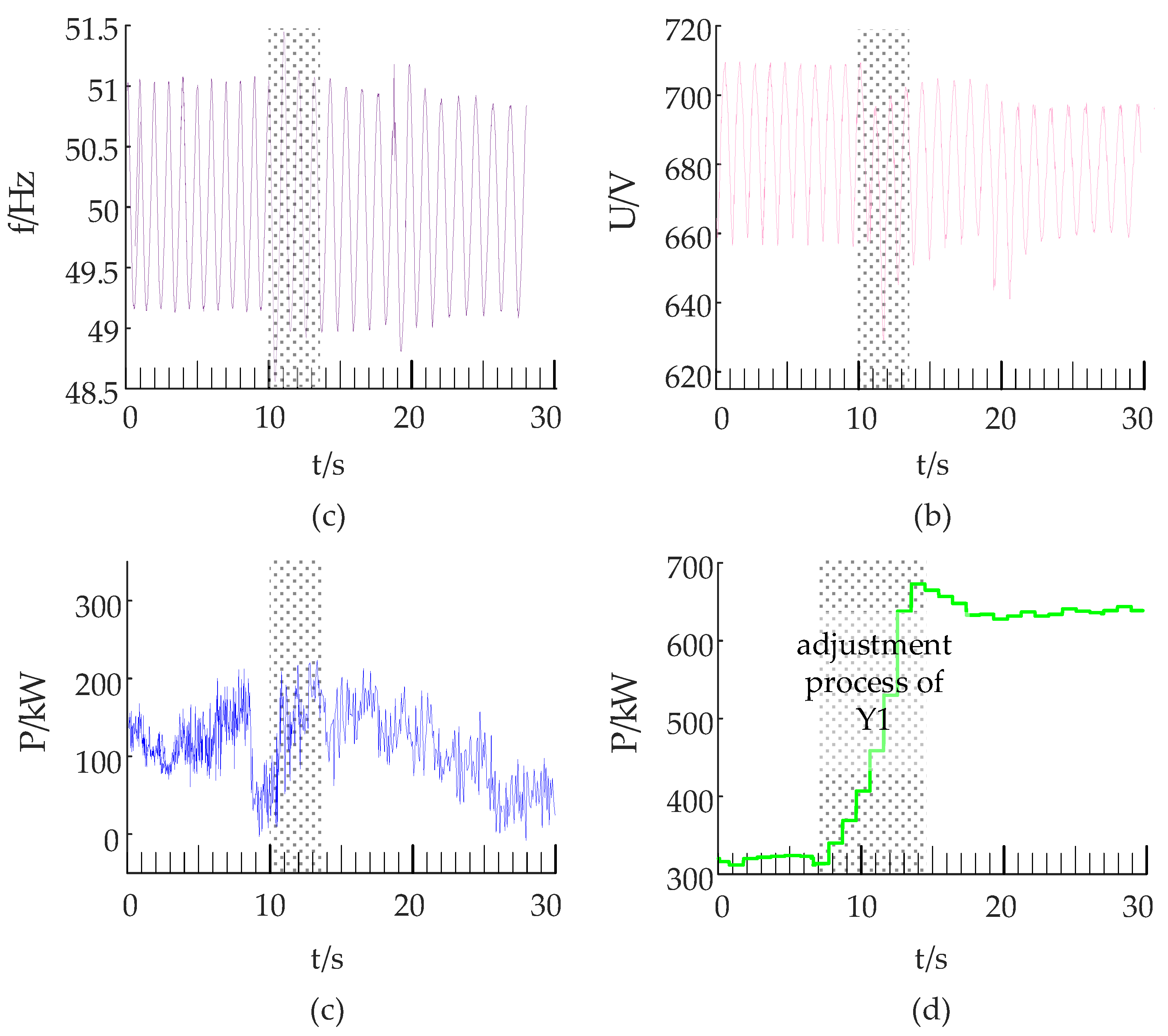
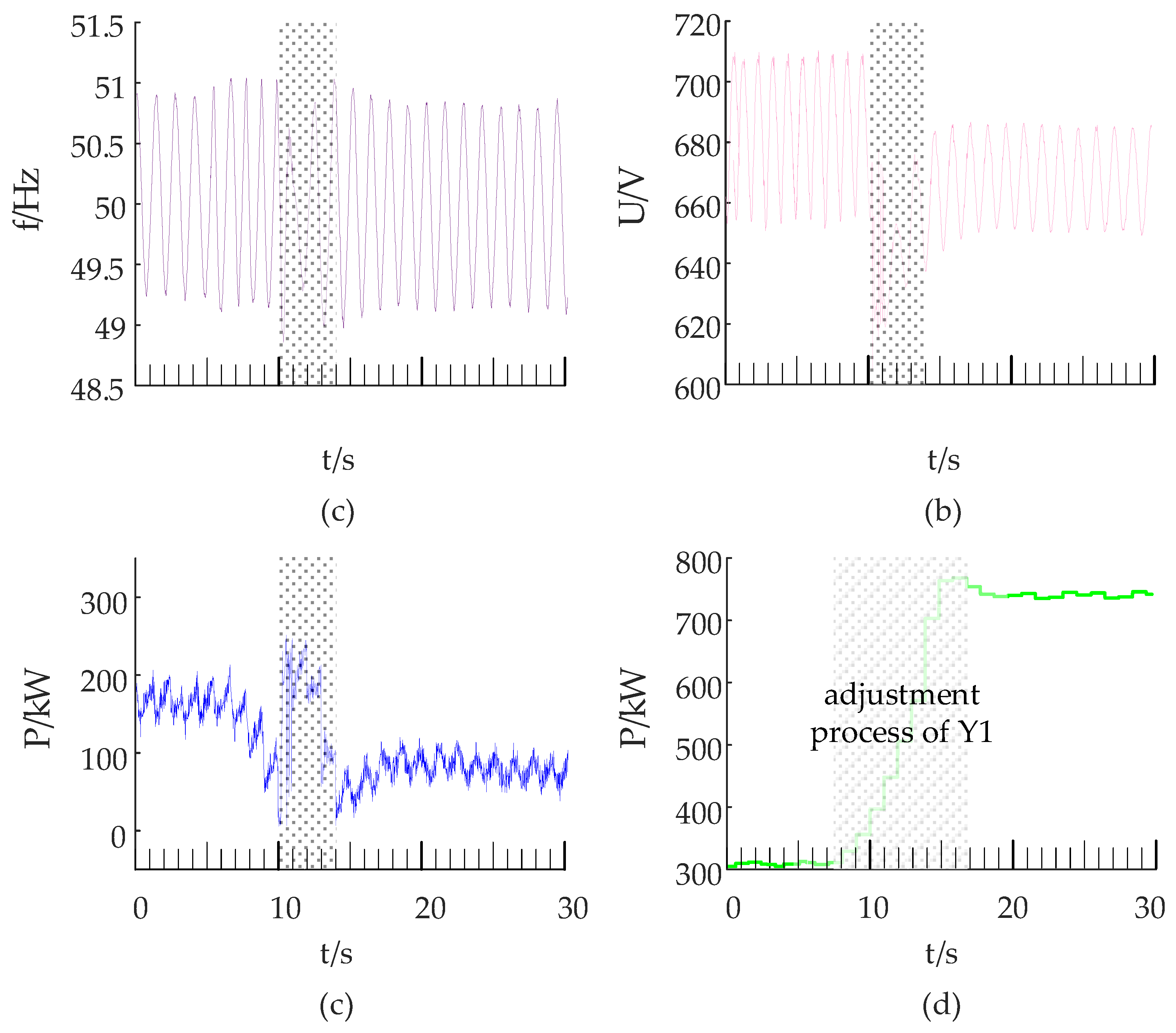
3.4. Splitting Process

To verify the support of the external power supply to the system, the output power of Y1 and Y3 is adjusted so that the output power of Gd is close to 0 after the black-start process is completed, and then Gd is shut down. After querying the operation log of the WPUs, it is known that the system voltage is pulled low when the Gd is shut down, and a network side failure is reported by the control systems of Y1 and Y3 and then the WPUs are stopped.
In response to the above problems, the following three aspects are some effective solutions. Firstly, a wind turbine with the ability to maintain the stability of voltage and frequency, which produces power according to the demand of the system, is the most ideal solution. Secondly, there are trade-offs when making a black start plan, and the weight coefficients of the multi-objective optimization should be considered cautiously. Thirdly, when the auxiliary power of the black-start thermal power plant is large, it is recommended to use a variable frequency start or soft start to reduce the impact on the system; and, when the power of the thermal power plant is large, multiple WPUs can be used to participate in the black start to speed up the black start process and reduce the power shortage.
Through many investigations, it is known that most of the operating WPUs do not have the ability to stabilize voltage and frequency. Therefore, in order to promote the application of wind farms to participate in a black start, a new technology such as a virtual synchronous machine can be used to study the WPU body.

4. Conclusions

In this paper, a black-start scheme in which the PMSG-based wind farm is taken as black-start power supply source is formulated: First, diesel generator is used as external supporting power supply for a WPU self-start. After all planned WPUs operate normally, the wind farm with the diesel generator and SVG is used to black start the simulated auxiliary load of thermal power plant. A field test of the proposed scheme is carried out on an actual wind farm in Jiangsu Province in China. Through the analysis of the test results, the following conclusions can be drawn:
(1)
A wind farm configured with an external power supply, balanced load and coordinated controls has black-start capability.
(2)
The self-starting and black starting are susceptible to wind speed and system disturbances. The slower the black-start process, the smaller the voltage and frequency impact of the system.
(3)
The external power supply provides voltage and frequency support and main power for the black start of the power grid.
(4)
The output of the WPUs relatively lags the rapid power demand of the black start. The power of the black start is mainly provided by the external power supply.
(5)
The magnitude of the reverse power of the external power supply is related to factors such as its initial output power, the power adjustment value and the preset time of WPUs.

5. Future Studies

(1)
Poor voltage and frequency stability, high real-time requirements and quick system status changes are observed during the wind farms’ participation in the black-start process, so coordinated control strategies and devices to synchronize the steps and control the transients need to be further studied.
(2)
When the auxiliary power of the black-start thermal power plant is large, the soft start technology and frequency conversion devices can be used as an effective means to improve the stability of the black-start system and to minimize the configuration capacity of the external power supply.
(3)
It is known that most of operating WPUs do not have the ability to stabilize voltage and frequency. Therefore, in order to promote the application of wind farms to participate in a black start, a new technology such as a virtual synchronous machine could be used to study the WPU body.

Author Contributions

Y.T. and M.T. conceived and designed the study; M.T. and C.Z. analyzed the data, performed the experiments and wrote the paper; C.Z. provide some actual wind power parameters and checked the results of this work. All the authors read and approved the final manuscript.

Funding

This work is supported by the National Natural Science Foundation of China (NSFC) (Grant No. 51877037).

Conflicts of Interest

The authors declare no conflict of interest.

References

  1. Golshani, A.; Sun, W.; Zhou, Q.; Zheng, Q.P.; Hou, Y. Incorporating Wind Energy in Power System Restoration Planning. IEEE Trans. Smart Grid 2019, 10, 16–28. [Google Scholar] [CrossRef]
  2. Sun, L.; Peng, C.; Hu, J.; Hou, Y. Application of Type 3 Wind Turbines for System Restoration. IEEE Trans. Power Syst. 2018, 33, 3040–3051. [Google Scholar] [CrossRef]
  3. Becker, H.; Naranovich, A.; Hennig, T.; Akbulut, A.; Mende, D.; Stock, S.; Hofmann, L. System restoration using VSC-HVDC connected offshore wind power plant as black-start unit. In Proceedings of the European Conference Power Electronics and Applications, Warsaw, Poland, 11–14 September 2017. [Google Scholar]
  4. Kai, S.; Yunhe, H.; Wei, S.; Junjian, Q. Renewable and Energy Storage in System Restoration. In Power System Control Under Cascading Failures: Understanding, Mitigation, and System Restoration; IEEE: Piscataway, NJ, USA, 2019; pp. 295–356. [Google Scholar] [CrossRef]
  5. Li, C.; Zhang, S.; Zhang, J.; Qi, J.; Li, J.; Guo, Q.; You, H. Method for the Energy Storage Configuration of Wind Power Plants with Energy Storage Systems used for Black-Start. Energies 2018, 11, 3394. [Google Scholar] [CrossRef]
  6. Aktarujjaman, M.; Kashem, M.A.; Negnevitsky, M.; Ledwich, G. Black start with dfig based distributed generation after major emergencies. In Proceedings of the 2006 International Conference on Power Electronic, Drives and Energy Systems, Trivandrum, India, 12–15 December 2006. [Google Scholar]
  7. Bizon, E.G.d.A.; Melo, F.D.S.d.; Salim, K.C.d.O. Analysis of insertion of wind power plants in the process of fluent restoration of the Brazilian interconnected power system. In Proceedings of the 2018 Simposio Brasileiro de Sistemas Eletricos (SBSE), Niteroi, Brazil, 12–16 May 2018. [Google Scholar]
  8. Jianfeng, D.; Yi, T.; Qi, W.; Xianbo, D.; Chenlong, L.; Lixin, F. Black start technology for local power grid via PMSG-based wind power generation. In Proceedings of the IEEE 3rd International Future Energy Electronics Conference and ECCE Asia (IFEEC 2017–ECCE Asia), Kaohsiung, Taiwan, 3–7 June 2017. [Google Scholar]
  9. Janning, J.; Schwery, A. Next generation variable speed pump-storage power stations. In Proceedings of the 13th European Conference on Power Electronics and Applications, Barcelona, Spain, 8–10 September 2009. [Google Scholar]
  10. Hu, Y.; Yu, Z.; Deng, C.; Wang, J.; Li, Y. Cause of generator startup failure during black-start of national wind/photovoltaic/energy-storage pilot station and its countermeasure. Electr. Power Autom. Equip. 2016, 37, 50–60. [Google Scholar] [CrossRef]
  11. Wang, A.; Gang, H.; Qiu, P.; Luo, X.; Pang, X.; Zhang, C. Self-Starting Analysis of New Energy System with Wind Power and Energy Storage. In Proceedings of the 37th Chinese Control Conference (CCC), Wuhan, China, 25–27 July 2018. [Google Scholar]
  12. Yuan, H.; Mi, Z.; Du, P.; Wan, Y.; Liu, L. Research of the transformer energization control strategy applied for storage-based wind farm self-start. In Proceedings of the IEEE Information Technology, Networking, Electronic and Automation Control Conference, Chengdu, China, 20–22 May 2016. [Google Scholar]
  13. Nuschke, M. Development of a microgrid controller for black start procedure and islanding operation. In Proceedings of the IEEE 15th International Conference on Industrial Informatics (INDIN), Poitiers, France, 24–26 July 2017. [Google Scholar]
  14. Thale, S.; Agarwal, V. A smart control strategy for the black start of a microgrid based on PV and other auxiliary sources under islanded condition. In Proceedings of the 37th IEEE Photovoltaic Specialists Conference, Seattle, WA, USA, 19–24 June 2011. [Google Scholar]
  15. Wei, T.; Hongtao, W.; Yingzhe, J. Construction and control strategy research of black start unit containing wind farm. In Proceedings of the Tencon IEEE Region, 10th Conference, Macao, China, 1–4 November 2015. [Google Scholar]
  16. Ye, M.; Liu, Y.; Du, K.; Gu, X. Black start scheme formation considering dynamic wind power penetration limit. In Proceedings of the 5th IET International Conference on Renewable Power Generation (RPG) 2016, London, UK, 21–23 September 2016. [Google Scholar]
  17. Xu, Z.; Yang, P.; Zeng, Z.; Zhang, Y.; Peng, J.; Zheng, Q. Study on black start strategy for multi-microgrids. In Proceedings of the IEEE Innovative Smart Grid Technologies-Asia (ISGT-Asia), Melbourne, VIC, Australia, 28 November–1 December 2016. [Google Scholar]
  18. Tang, Y.; Dai, J.; Wang, Q.; Feng, Y. Frequency Control Strategy for Black Starts via PMSG-Based Wind Power Generation. Energies 2017, 10, 358. [Google Scholar] [CrossRef]
  19. Li, C.; Zhan, P.; Wen, J.; Yao, M.; Li, N.; Lee, W. Offshore Wind Farm Integration and Frequency Support Control Utilizing Hybrid Multiterminal HVDC Transmission. IEEE Trans. Ind. Appl. 2014, 50, 2788–2797. [Google Scholar] [CrossRef]
  20. Li, J.; Su, J.; Yang, X.; Zhao, T. Study on microgrid operation control and black start. In Proceedings of the 4th International Conference on Electric Utility Deregulation and Restructuring and Power Technologies (DRPT), Weihai, Shandong, China, 6–9 July 2011. [Google Scholar]
  21. Wang, J.; Mu, L.; Zhang, F.; Zhang, X. A Parallel Restoration for Black Start of Microgrids Considering Characteristics of Distributed Generations. Energies 2018, 11, 1. [Google Scholar] [CrossRef]
  22. Liu, L.; Wu, J.; Mi, Z.; Sun, C. A feasibility study of applying storage-based wind farm as black-start power source in local power grid. In Proceedings of the International Conference on Smart Grid and Clean Energy Technologies (ICSGCE), Chengdu, China, 19–22 October 2016. [Google Scholar]
  23. Li, L.; Yuechao, W.; Yi, Z. The energy storage system control research based on black-start. In Proceedings of the China International Conference on Electricity Distribution (CICED), Shenzhen, China, 23–26 September 2014. [Google Scholar]
  24. Yeting, W.; Yuxing, D.; Xiwei, Z.; Ye, W.; Bin, X. Application of island microgrid based on hybrid batteries storage. In Proceedings of the International Conference on Renewable Energy Research and Application (ICRERA), Brasov, Romania, 19–22 October 2014. [Google Scholar]
  25. Valle, R.G.d.; Cotorogea, M.; Rabelo, B.; Hofmann, W. On the Emulation of an Isolated Wind Energy Conversion System: Experimental Results. In Proceedings of the Electronics, Robotics and Automotive Mechanics Conference (CERMA), Cuernavaca, Mexico, 22–25 September 2009. [Google Scholar]
  26. Zhu, L.; Pan, Z.; Xu, G. Black Start with DFIG-Based Wind Turbines Using Improved Virtual Synchronous Control. In Proceedings of the 21st International Conference on Electrical Machines and Systems (ICEMS), Jeju, Korea, 7–10 October 2018. [Google Scholar]
  27. Xu, Z.; Yang, P.; Zhang, Y.; He, T.; Peng, J.; Zheng, Q. Control devices development of residential single-phase PV-ESS microgrid. In Proceedings of the IEEE Innovative Smart Grid Technologies–Asia (ISGT-Asia), Melbourne, Australia, 28 November–1 December 2016. [Google Scholar]
  28. Xu, Z.; Yang, P.; Zeng, Z.; Peng, J.; Zhao, Z. Black Start Strategy for PV-ESS Multi-Microgrids with Three-Phase/Single-Phase Architecture. Energies 2016, 9, 372. [Google Scholar] [CrossRef]
  29. El-Zonkoly, A.M. Renewable energy sources for complete optimal power system black-start restoration. IET Gener. Transm. Distrib. 2015, 9, 531–539. [Google Scholar] [CrossRef]
  30. Xiaoyu, S. The “black start” test of the National Scenery Storage and Loss Demonstration Power Station was successful. State Grid News, 14 October 2014. [Google Scholar]
  31. Lei, H.; Yan, X.; Xinyan, X. The first domestic wind power black start test was completed by State Grid Jiangsu Jiangsu Electric Power Co., LTD. State Grid News, 10 August 2017. [Google Scholar]
  32. Bahrman, M.; Bjorklund, P. The New Black Start: System Restoration with Help from Voltage-Sourced Converters. IEEE Power Energy Mag. 2014, 12, 44–53. [Google Scholar] [CrossRef]
  33. Blasco-Gimenez, R.; Villalba, S.A.; Rodríguez-D’Derlée, J.; Bernal-Pérez, S. Diode based HVDC link for the connection of large off-shore wind farms with self start capability. In Proceedings of the 14th European Conference on Power Electronics and Applications, Birmingham, UK, 30 August–1 September 2011. [Google Scholar]
  34. Jie, D.; Harley, R.G. Islanded microgrids black start procedures with wind power integration. In Proceedings of the IEEE Power & Energy Society General Meeting, Vancouver, BC, Canada, 21–25 July 2013. [Google Scholar]
  35. Li, L.; Songjie, S.; Gang, W. The control strategy research of wind power and storage based on the black start. In Proceedings of the China International Conference on Electricity Distribution, Shenzhen, China, 23–26 September 2014. [Google Scholar]
Figure 1. Topological structure diagram of the wind farm.
Energies 12 02144 g001
Figure 2. Topological structure diagram of a wind power unit.
Energies 12 02144 g002
Figure 3. Field test system diagram for black start.
Energies 12 02144 g003
Figure 4. The logic relationship of SCDBS.
Energies 12 02144 g004
Figure 5. The hardware framework of SCDBS.
Energies 12 02144 g005
Figure 6. The control strategy of SCDBS.
Energies 12 02144 g006
Figure 7. (a) equipment installation and system debugging, (b) charging for the primary equipment, (c) powering Lb, (d) self-tarting Y1, (e) self-tarting Y3, (f) black starting La.
Energies 12 02144 g007
Figure 8. (a) system frequency, (b) system voltage, (c) active power, (d) reactive power.
Energies 12 02144 g008
Figure 9. (a) system frequency, (b) system voltage, (c) active power, (d) reactive power.
Energies 12 02144 g009
Figure 10. (a) system frequency, (b) system voltage, (c) active power of Gd, (d) active power of Y1.
Energies 12 02144 g010
Figure 11. (a) system frequency, (b) system voltage, (c) active power of Gd, (d) active power of Y1.
Energies 12 02144 g011
Figure 12. (a) system frequency, (b) system voltage, (c) active of Gd, (d) active power of Y1.
Energies 12 02144 g012
Table 1. Equipment list for the black-start test.
SymbolEquipmentType
Gddiesel generator400 kW
Laauxiliary machine in thermal power690 V/3000 kVA
Lbbalanced load690 V/1000 kVA
G1, G2PMSGGW115/2000 kW
M1, M2cabin equivalent load40–60 kVA
CV1, CV2full-power converterGW115/2000 kW
T100step-up transformer500 kVA
T101, T201, T301box-type transformer2200 kVA
T102, T202cabin load transformer90 kVA
QF101circuit breaker for Gd400 V–2000 A
QF102, QF202circuit breaker for WPU690 V–2000 A
QF103, QF203circuit breaker for full-power converter690 V–2000 A
QF104, QF204circuit breaker for cabin equivalent load400 V–100 A
QF302circuit breaker for load400 V–1500 A
QF106, QF206, QF306circuit breaker for box-type transformer35000 V–100 A
Table 2. The list of parameters for balance load Lb connecting.
SequenceParameterValueParameterValueParameterValue
Part 1Umax707.5 VUmin669.65 VVoltage fluctuation2.95%
fmax50.71 Hzfmin49.24 HzFrequency fluctuation1.52%
Qmax8.6 kVarQmin−16.6 kVar
Part 2Umax718.2 VUmin629.22 VVoltage fluctuation8.81%
fmax52.01 Hzfmin48.391 HzFrequency fluctuation4.03%
Qmax22.3 kVarQmin−28.1 kVar
Table 3. The list of parameters of wind turbine generator for self-starting process.
No.Wind SpeedParameterMaxMinMax Fluctuation Ratio(%)Result
15.85 m/sU (V)715.98689.663.80Last 11 s
successful
I (A)272.41//
f (Hz)50.6049.301.41(0.71 Hz)
22.55 m/sU (V)714.49652.15.60Last 83 s
successful
I (A)223.83//
f (Hz)51.1348.942.25(1.1 Hz)
34.26 m/sU (V)823.47568.9119.34Failed
I (A)418.65//
f (Hz)52.3947.295.42(2.7 Hz)
45.91 m/sU (V)822.17565.3219.16Failed
I (A)427.09//
f (Hz)52.73946.417.18(3.6 Hz)
54.53 m/sU (V)818.99562.6418.70Failed
I (A)384.13//
f (Hz)52.3547.724.70(2.4 Hz)
63.65 m/sU (V)695.72640.057.24Last 32 s,
successful
I (A)231.81//
f (Hz)51.1249.002.24(1.1 Hz)
Table 4. The list of parameters for starting simulation auxiliary load.
SequenceParametersValue
Initial state before black startPower of La (kW)100200300
Initial voltage (V)690.0710.0710.0
Preadjusted power (kW)200300400
Preadjusted time (s)5.05.04.5
Main parameters of the black start processMax power of Gd (kW)280250230
Min power of Gd (kW)−67−20−5
Max Voltage (V)710.4710.2710.7
Min voltage (V)620.2629.1650.2
Max frequency (Hz)52.0651.4351.09
Min frequency (Hz)48.3148.5749.15
Startup duration (s)1.52.23.2

