Article

Large Eddy Simulation of Self-Excited Oscillation Pulsed Jet (SEOPJ) Induced by a Helmholtz Oscillator in Underground Mining

1
School of Energy and Power Engineering, Wuhan University of Technology, Wuhan 430063, China
2
School of Power and Mechanical Engineering, Wuhan University, Wuhan 430072, China
*
Authors to whom correspondence should be addressed.
Energies 2019, 12(11), 2161; https://doi.org/10.3390/en12112161
Submission received: 10 May 2019 / Revised: 30 May 2019 / Accepted: 4 June 2019 / Published: 5 June 2019

Abstract

:
Pulsed waterjet can break rocks effectively by taking advantage of the water hammer effect, and is thus widely used in mining, petroleum, and natural gas fields. With the aim to further clarify the flow field characteristics of pulsed jets induced by a Helmholtz oscillator, large eddy simulation was conducted under different operating pressures. The velocity distribution, mean flow field, and the coherent structure were examined using the oscillators of different cavity lengths and diameters. The results clearly showed that the major frequency of jet pulsation gradually increased with the increase of operating pressure. A stable periodic velocity core was formed at the outlet of the Helmholtz oscillator, while the external flow field was subjected to periodic impact. As a result, the ambient fluid was strongly entrained into the jet beam. With the increase of the cavity length, the length of the core segment decreased while the energy loss caused by the cavity increased, which was also accompanied by a rapid attenuation of the axial velocity at the jet outlet. The coherent structure of the jet in the oscillator with small cavity diameter was more disordered near the nozzle outlet, and the vortex scale was larger. The effect of cavity diameter can be reflected in the feedback modulation of the jet in the cavity. Compared with the conical nozzle, the length of the core section of the jet was shorter, but the jet had better bunching, a smaller diffusion angle, and better mixing performance. These results provide a further understanding of the characteristics of pulsed water jet for better utilizations in the fields of energy exploitation.

1. Introduction

Self-excited oscillation pulsed jet (SEOPJ) is widely used in engineering applications as an efficient tool to enhance the impact capability. The pulsed jet with water flowing through Helmholtz oscillator has stronger impact force than continuous jet (see Figure 1). Li et al. [1] designed a new drilling tool to improve the drilling rate in deep wells based on the theory of jets pulsation. Oil field tests in five wells showed good applicability of the tool to bit types, formation, drilling densities, flow rates, and dynamic hydraulic drilling motors, etc. As a result, the penetration rate was improved ranging from 10.1 to 31.5%. Ge et al. [2] proposed a novel method that used a self-propelled water-jet nozzle to dredge blocked boreholes in coal seams in order to improve the coal bed methane output and coal mine safety. The nozzle inlet pressure was optimized and a field experiment on the blockage removal of blocked coal bed methane drainage boreholes using the proposed method was conducted. Lu et al. [3] designed a self-propelled water-jet drilling nozzle to drill three-type boreholes to improve gas extraction and drilling experiments were conducted to optimize the nozzle configuration. As a generator of SEOPJ, attention has been paid to the Helmholtz oscillator and extensive research has been done by Rockwell and Morel [4,5,6]. The unsteady flow phenomenon in SEOPJ is combined with various theories such as fluid dynamics, fluid resonance, and hydroelasticity, which makes it difficult to measure the flow patterns and vortex structures. In particular, an experimental study was conducted to characterize the discrete model by the change of cavity length and to give stable working regions under various parameters [7]. The identification of the complex mechanism responsible for this phenomenon is difficult because it is the result of multiple factors and data acquisition of all the instantaneous fields simultaneously is unavailable under the existing measurement techniques [8].
Since numerical simulation has quickly become an important means of research, the flow characteristics of many complex turbulent flows can be studied by this method. Stanley et al. [9] studied the development of free jet flow and the unsteady flow characteristics of free jet shear layer by direct numerical simulation (DNS). Bogey et al. [10,11] analyzed the effect of filtering and Smagorinsky dynamic model in a large eddy simulation on energy consumption. Kim et al. [12] studied the effects of initial momentum thickness and Reynolds number on the free jet flow in circular holes by large eddy simulation (LES), and found that the flow characteristics of free jet are closely related to initial momentum thickness and Reynolds number. Bonelli et al. [13] carried out a comprehensive investigation of mixing properties in near- and intermediate-fields by LES. A qualitative view of the jet coherent structures and a quantitative analysis of the turbulence scales are also provided. Variable-density turbulent round jets and swirling turbulent jet flows were studied with the aid of large-eddy simulation [14,15]. Peng et al. [16] used a compressible mixture flow method to numerically simulate cavitating water jet. Luo et al. [17] and Ji et al. [18] investigated pressure fluctuation and vortex shedding of twisted hydrofoil by large eddy simulation. With the rapid development of computing capacity, LES has been used to simulate a variety of complex turbulent flows [19,20].
As for Helmholtz oscillator, several experiments [21,22,23,24,25] and numerical simulations [26,27,28,29,30] have been conducted to reveal the self-excited mechanism, frequency characteristics, and pressure fluctuation. The impact characteristics of the jets were quite different from those of continuous jets. Structure parameters and working parameters needed to be in the appropriate value to achieve good results so that the erosion ability was much higher than that of a conical nozzle. The surface crack propagation range, depth, and strength of the low-frequency jet were significantly increased compared with the high-frequency jet. It is certain that the internal mechanism and external characterization of the pulsed jet are closely related, while the flow characteristics at high Reynolds numbers are different from those at lower ones. A detailed description of the flow needs to be improved and further studied.
On this account, research was motivated with the goal to identify the flow characteristics and vortex structure which was affected by parameters. Lip-ribbed and inner-ribbed nozzles were investigated and compared with smooth ones by LES which were validated using the PIV and LIF measurements. The results showed that the ribbed jets performed good mixing characteristics and the inner-ribbed nozzle induced high-flow fluctuations behind the rib, which were characterized by a fluid flapping motion due to the periodic reattachment of the flow on the pipe wall [31]. Li et al. [32] reported the flow characteristic of highly under-expanded jets from different nozzle geometry, i.e., the circular, elliptic, square, and rectangular, by using LES. Great differences were shown on the formation and development of the intercepting shocks, while the elliptic jet had the slowest penetration rates. Three separated jets were numerically simulated by Hidouri et al. [33], and validated by experimental data of the non ventilated jets. The obtained results show that there is an obvious improvement of mixing ability compared to the single jet. In the present study, three dimensional large eddy simulations of turbulent pulsed jets induced by a Helmholtz oscillator were carried out so that the flow characteristics of nozzles under various operating conditions, cavity lengths, and cavity diameters could be studied. By analyzing the flow characteristics of nozzles with different structures and operating parameters, the applicability and performance of the nozzles can be distinguished. The research results can be used as the theoretical basis for selection and design of SEOPJ nozzles in underground mining.

2. Computational Details

2.1. Flow Configuration

The profile and the schematic view of Helmholtz oscillator are shown in Figure 2. The Helmholtz oscillator consists of an upstream nozzle, a downstream nozzle, an upstream impinge wall, a downstream impinge wall, and an oscillation cavity. The two nozzles are on the inlet and outlet axis of the cavity respectively. The upstream impinge wall, downstream impinge wall, and side walls form an internal chamber which is called a Helmholtz oscillator. The upstream nozzle diameter is d1, the downstream nozzle diameter is d2, the impinge wall angle is α, the oscillation cavity length is Lc, and the oscillation cavity diameter is Dc. The Reynolds number of the flow is based on the jet diameter d2 and its (constant) bulk velocity Ub with
R e = U b d 2 ν
The Re number was between 1 × 10⁵ and 2 × 10⁵ in this study. The cavity length ratio varied from 1.0 mm to 4.0 mm and the cavity diameter ratio varied from 4.0 to 10.0. The impinge wall angle was α = 120° and the nozzle diameter ratio was d2/d1 = 1.2. The parameters are shown in Table 1.

2.2. Governing Equation

The filtered three-dimensional incompressible Navier–Stokes equations are given by:
Continuity : u ¯ i x i = 0
Momentum : u ¯ i t + u ¯ i u ¯ j x j = 1 ρ p ¯ x i + ν 2 u ¯ i x j x j τ i j x j
In these equations, ρ, u ¯ and p ¯ are medium density, velocity and pressure respectively. The tensor ui is the instantaneous velocity and xi denotes the three-dimensional coordinate directions. τ i j is the modified sub-grid-scale (SGS) tensor. The SGS stress tensor, τ i j = u i u j ¯ u i ¯ u j ¯ was modelled using the dynamic SGS model by Smagorinsky [34] together with the least-square method suggested by Lilly [35]. The construction the enclosure of SGS tensor is the key to solve the large eddy simulation of turbulence.
In this case, the deviatoric part of τ i j is modeled as:
τ i j δ i j 3 τ k k = 2 ν τ S i j
where δ i j is Kronecker’s delta, and v t is the eddy viscosity, and S i j is the resolved scale strain rate tensor, defined as
S i j = 1 2 ( u i / x j + u j / x i ) .
The magnitude can be defined as
S ¯ = ( 2 S i j S i j ) 1 / 2 .
The dynamic SGS model for the eddy viscosity is
ν τ = ( C s Δ ) 2 | S ¯ |
where C s is coefficient, Δ = ( Δ x Δ y Δ z ) 1 / 3 , Δ x , Δ y , Δ z are cell length of three coordinate directions respectively.
This method assumes that the energy production and dissipation of the small scales are in equilibrium. The Cs was adjusted from 0.1 to 0.2 obtain a closer result and 0.12 was selected as a constant for subsequent calculation.

2.3. Computational Domain and Boundary Condition

The computational domain including the nozzle and the external flow area is shown in Figure 3. The inlet pipe before the upstream nozzle is a conical pipe with a cone angle of 13.5°. The length of the upstream pipeline is about 5 times of the upstream inlet diameter Di, in order to ensure the stability of the incoming flow. The length of the straight section of the upstream nozzle is 3 times of the nozzle diameter d1 and the length of the straight section of the lower nozzle is 3 times of the nozzle diameter d2. The length and diameter of the outflow field are 50d2 and 20d2, respectively, to ensure the fully development of the flow field while minimizing the number of grids and ensuring the convergence speed.
The simulation was conducted using the three dimensional ANSYS FLUENT 15.0 code in which the equations were solved by the finite volume method applied on a non uniform grid. The flow was assumed to be unsteady, controlled by the LES equations together with the continuity equation. Pressure boundary conditions were applied on the inlet and outflow for outlet boundaries. The second-order upwind scheme was adopted for spatial discretization of the convection terms and the second-order implicit scheme was used for time advancement. The SIMPLE algorithm was employed to couple the pressure and velocity.
The whole calculation area adopted the hexahedral structure grid, shown in Figure 3b–d. The flow shear layer, jet collision, and other areas such as the upstream nozzle, the downstream nozzle outlet and the vicinity of the wall surface of the chamber were refined. The grid y+ was about 1 in the near-wall region and below 10 in the shear layer, surface, sharp angle, and other complex flow regions, which conformed to the calculation requirements of large eddy simulation. The filter of large eddy simulation was closely related to the scale of the grid, so the grid scale also had a great influence on the SGS model. Different levels of fine grid was different for solving turbulent motion range, while different SGS model under the same conditions of the calculation results were also different. So the SGS models matched with grid each other, and grid scale was positively related to filtering scale.
The mesh independency was proved in Table 2, which indicated that the differences could be neglected between the medium and fine resolution meshes. The medium mesh was selected as final grid, which varied from 10 million to 14 million depending on the chamber size (see Figure 3). When the mesh was fine enough to solve the laminar sublayer, the wall shear stress was obtained from the laminar stress–strain relationship:
u ¯ u τ = ρ u τ y 1 μ
where u ¯ is average velocity, u τ is shear velocity, y1 is mesh thickness of the first layer.

3. Results and Discussion

3.1. Validation

Pulsed water jets act on materials under dynamic loads with extremely high instantaneous pressure, the magnitude and distribution of which determine the failure capability of the jets. The self-excited oscillation pulsed jet (SEOPJ) is highly unsteady turbulent flow, due to the existence of Helmholtz chamber. The jet pressure remains almost constant in the upstream tapered pipe. When the jets flow through the Helmholtz cavity, the pressure pulsation is generated. Discontinuous high-pressure micro-clusters are formed on the central axis of the Helmholtz cavity, and the peak pressure is higher than the inlet pressure. The pressure pulsation at the nozzle outlet was also obtained. The fluctuating frequency is one of the performance indexes of the SEOPJ.
The same nozzle parameters as in the literature were selected for calculation, and the pressure fluctuation at the nozzle outlet was obtained. Figure 4 shows the marginal spectrums obtained at nozzle outlet compared with the experiment results measured by Liu et al [29]. If we choose the frequency at which the spectrum is the highest as the true value of fp, it is fp = 0.49 Hz for the LES case and fp = 0.42 Hz for the experiment. The tested curve coincides well with the calculated one. In conclusion, the LES prediction of the oscillation agrees well with the measurement.

3.2. Frequency Spectrums

As for the oscillator used in the present study, the upstream nozzle diameter was d1 = 2.6 mm, which was much smaller than that in the literature [29]. With the decrease of nozzle structure parameters, the Reynolds number of jet flow increase under the same operating pressure. While the operating pressure varies from 1.0 MPa to 3.0 MPa, the change in Reynolds number corresponds to the change in the flow characteristics of the nozzle. For nozzles of the same configuration size (Lc/d1 = 2, Dc/d1 = 8), the outlet fluctuating frequency is positively correlated with inlet pressure. Figure 5 shows the frequency spectrums under different operating pressures. The curve has multiple peaks in the frequency spectrum, and the highest value is called the major frequency. The high-frequency band has a multifarious relationship with the major frequency, and the amplitude decreases as the frequency increases. The reason is that secondary vortices accompanied by vortex shedding also affect the flow field of the cavity, which is not the main factor associated with jet oscillation. With increasing operating pressure, the major frequency of pulsation leans in the direction of high frequency. When the operating pressure is 3.0 MPa, the frequency is 68 Hz.

3.3. Transient Flow Field

In any section of submerged water jet, the transverse velocity is much smaller than the axial velocity, which can be ignored approximately [36]. Therefore, it can be considered the velocity of the jets as the axial velocity, and the impact on the target is mainly from the axial velocity, which is consistent with the conclusion obtained in theoretical analysis and experiment [37]. Figure 6 shows the contours of axial velocity distribution at different moments. Before the upper nozzle, the conical tube was used to convert the pressure energy into kinetic energy, in which the velocity was increasing constantly. When the jet entered the Helmholtz cavity, the velocity remained approximately constant near the upper nozzle. Under the modulation effect of Helmholtz cavity, the jets showed obvious self-oscillation characteristics. There was a great velocity gradient between the jet beam and the water in the oscillating cavity, so a strong shear flow occurred in the tangential direction which generated shear layer instability and vortex rings. Because of the limitation of the lower nozzle exit, it collided with the collision wall and intermittently perturbed the jet flow through the reflection of the chamber. When the jet flow was close to the downstream nozzle, the velocity fluctuating phenomenon was generated, and discontinuous elastic high-speed fluid microclusters was formed with a peak velocity reaching over 1.3 times of the inlet velocity. The position of the high-speed microclusters in the cavity changed periodically, but the peak velocity was basically at the same level. After the pulsed water jets ejected from the downstream nozzle, the velocity field of the outflow field fluctuated periodically, passed far away, and ultimately dissipated.
In the external flow field, the instantaneous velocity of jet flow is asymmetric along the central axis. With the energy exchange of shear motion between the high-speed water jet and the ambient fluid, the surrounding static fluid is constantly involved into the jet flow, which widens the jet boundary and reduces the radial velocity. In the outflow field, the outer boundary of the jet with zero velocity can be observed, and the velocity gradient shows obviously from the core area of the jet to the outer boundary. In s/d2 = 0~5, the jet is a high-speed discrete slug flow, and jet velocity attenuates in s/d2 = 5~10. After s/d2 > 10, attenuation speed slows down, and reaches the end of the submerged jet while the spray distance is s/d2 = 20 with axis speed at around 20 m/s. The jet slug performs expansion, separation from the mainstream, and eventually dissipates in ambient fluid due to the exchange of jet pulse and low-speed ambient fluid momentum.
Figure 7 and Figure 8 show the static pressure and RMS pressure variation of SEOPJ with time interval of Δt = 5 ms, while Lc/d1 = 4, Dc/d1 = 8, Pi = 2.0 MPa. A symmetrical area of low pressure is formed in the chamber, moving from the upstream nozzle to downstream nozzle. In Figure 7c the low-pressure area disappears near the downstream collision wall while a new area of low pressure is forming upstream. The low pressure area near the upper nozzle is formed periodically, and when it reaches the downstream impinge wall, it affects the jet flow at the outlet of the downstream nozzle. Therefore, the jet flow formed in the outflow field is also a periodic pulsation. The RMS pressure variations do not change with time.
As can be seen in Figure 6, Figure 7 and Figure 8, the outer boundary of the instantaneous flow field is not a straight line, which can be observed as irregular shapes. This was because spanwise vortexes of different scales are formed on the outer boundary of the jet flow, and periodically increase in scales with the jet flow, and then break into small-scale vortexes. The evolution of vortex structure will be analyzed in detail later.

3.4. Mean Flow Field

Since the boundary layer of the jets is in a turbulent state, the instantaneous velocity of the jet is unsteady and oscillating. In order to better analyze the influence of the cavity length and diameter on the velocity change rule of external flow field, the jet velocity we studied was the average velocity in the statistical sense, that is, the velocity did not change with time, but it was only a function of position. The time-average velocity distribution of different structure parameter and cross-section at different locations were studied [38].
The cavity length is closely related to the initial instability and the perturbation feedback modulation, and it is one of the key parameters determining the intensity of self-excited oscillations. Figure 9 shows different axial velocity attenuation curve under different parameters (Dc/d1 = 8, α = 120°, Lc/d1 = 1, 2, 3, 4), where X-coordinate is the dimensionless distance of Y direction, Y-coordinate is the dimensionless velocity of Y direction. The origin of coordinates is located in the center of the nozzle exit. The shorter the cavity length is, the faster the relative velocity in the cavity decreases, while the velocity of cavity outlet remains the same. Compared with the traditional conical nozzle, the SEOPJ nozzles have a section which causes energy loss in the cavity, so the length of jet core section is shorter. With the increase of the cavity length, the length of the core section of the SOEPJ nozzle decreases. Thus, the jets flowing into the external flow field become more disordered, and the entrainment mixing ability is stronger. While entering the outflow field, the velocity on jet axis gradually decays. Finally, when the distance of the jet reaches 30d2, the velocity of the nozzles with different cavity length tend to be the same.
Figure 10 shows the distribution of the dimensionless velocity uy/u0 along axial direction for four different cavity lengths (Dc/d1 = 8, Lc/d1 = 1, 2, 3, 4), where u0 is the average velocity at the nozzle outlet. Y-coordinate is the dimensionless distance y/d2, X-coordinate is the dimensionless velocity uy/u0.
As can be seen from Figure 10, the axial velocity curves of the jet present an approximate symmetrical distribution on both sides of the axis. On the same cross-section, the velocity is the highest at the axis, then decreases as the increasing of distance from the axis, and finally tends to be uniform. As s becomes larger, the axial velocity decreases, and the velocity near the outer boundary of the jets increases slightly.
When Lc/d1 = 1, the jets still maintained the initial velocity near the axis of nozzle outlet. With the development of the jets, the jet width of the initial velocity was gradually reduced. The jet turned into the transition segment where it was only maximal at the axis at s/d2 = 5 cross-section. After entering the transition segment, the instability of jet flow increased, energy exchange took place with the surrounding fluid, which led to the rapid attenuation of the axial velocity and tended to be stable at s/d2 = 20.
As can be seen from the curve at s = 2.5d2, the width of the velocity core decreases with the increase of the cavity diameter ratio from 1.0 to 4.0. The jet ejected from the nozzle with a short cavity length is more stable, the velocity core of the jet is wider. Although stable and uniform jet can achieve better results in many applications, the SEOPJ nozzles focus on instantaneous impact force and jet pulse effect. The Helmholtz chamber with too short cavity has limited the modulation effect on the jet, which is not conducive to the generation of water hammer effect.
Figure 11 shows the axis velocity attenuation at different models (with the other parameters remaining unchanged and only the cavity diameter changed). It can be seen from the figure that the axial velocity remains stable in the chamber, and the jets gradually decrease with the increase of the jet distance after ejecting from the nozzle. The attenuation curves of different cavity diameters basically coincide, so it can be seen that, within the scope of this study, the influence of cavity diameter on the axial velocity attenuation is very small, which is far less than that of cavity length. For free jet, velocity along the axial direction gradually decays, while the SEOPJ also conform to this rule. High speed water flows into the Helmholtz cavity from the upstream nozzle; the cavity length has a greater influence on the exit velocity. After all, the influence of cavity diameter is mainly manifested in intraluminal feedback modulation. Since the velocity drops after ejection in the chamber as ladder-shaped, the velocity core of the SEOPJ is much shorter than that of the free jet even if the cavity length is taken into account, and the energy loss in the chamber can not be ignored.
As can be seen from the Figure 12, when the cavity length is the same, the velocity distribution of nozzles with different cavity diameters in the outflow field has a similar change rule, where the velocity curves of Dc/d1 = 4 and 6 basically coincide. As can be seen from the previous section, when L/d1 ≥ 3, the jets basically disappeared in the velocity core segment at s/ d2 = 2.5. When L/d1 = 4, the influence of cavity diameter on the vicinity of the axis (x = 0~0.25d2) was not obvious. The cavity diameter had no significant influence on the jet velocity in this region, and no velocity core was observed. Moreover, the axial velocity had the same attenuation law, and the axial velocity of the four cavity diameters basically coincided at each position. However, at x = 0.25d2~d2, the influence of cavity diameter on the external velocity began to be revealed. At the same radial position, the larger the cavity diameter was, the lower the axial velocity of the jet flow was. With the increase of jet distance, the differences between velocity curves reduced and almost coincided at s/d2 = 10.
The cavity diameter determines the space inside the cavity. With the increase of the space for energy storage and modulation in the cavity, the vortexes develop fully and affect large amounts of area. As a result, the overall vortex movement of the fluid in the cavity is strong and has a great influence on the length of the jet beam in the chamber. However, when the dimensionless cavity diameter is 10, the cycle of vortex formation, reflection, collision, and crushing becomes long, and the vortex strength feedback is not strong enough, so that no effective axial pulsation is formed.

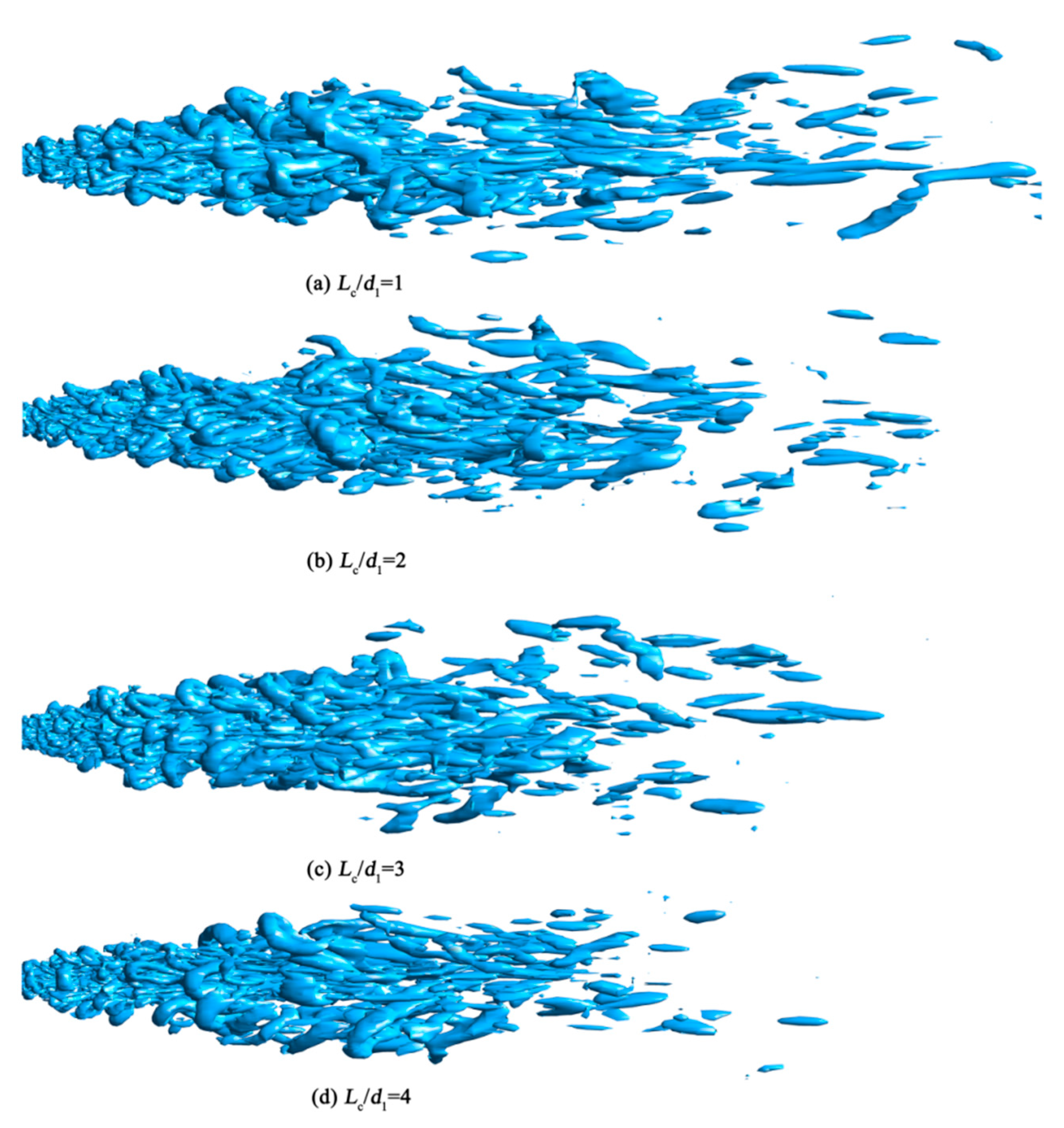
3.5. Coherent Structure

Coherent structure is the key mechanism that turbulent flow generates and maintains, which has been used to analyze jets flow in recent years [13]. Q criterion is one of the vortex criterion under Euler system defined as Q = 1 / 2 ( | Ω | 2 | S | 2 ) , Ω is vorticity tensor, reflecting the rotation effect; S is strain rate tensor, reflecting the deformation effect.
The value of Q represents the magnitude of vortex intensity. Figure 13a–d shows the coherent structure of SPEOJ flow under different Q-criterion number (Q = 1 × 10⁹, 1 × 10⁸, 1 × 10⁷, 1 × 10⁶), while Figure 13e is the conical nozzle as a contrast under the same operating condition and nozzle diameter. When the Q value was large (see Figure 13a) the vortex structure could only be observed near the nozzle outlet, and there was a closed vortex ring near the outlet. The vortex structure in the core area was mainly a braided streamwise vortex which was closely distributed, because the jet velocity was uniform in the core area, and the streamwise vortex was generated by the circumferential shear motion of turbulence. When the value of Q was small, the vortex structure grew radially along the flow direction and distributed basically symmetrically. Moreover, it was conical as a whole and the tensile angle became larger. The external of vortex was dominated by the spanwise vortex due to Kelvin–Helmholtz instability, while the core area was still dominated by the streamwise vortex. In the middle region, the streamwise vortex and the spanwise vortex existed together and entangled with each other, so that the size of the vortex was uneven. As can be seen in Figure 13d, the jet velocity was basically the same with that of the ambient fluid at a distance of 80 mm. With the increase of the jet distance, the external vortex no longer grew along the radial direction, and the spanwise vortex faded away. The size of the streamwise vortex decreased and its distribution was sparse. At this time, vortex shedding was observed at a distance of 100 mm.
In general, the spacing of the spanwise vortexes was relatively uniform, and the size of the vortex structure at the same axial position was similar, but its shape was complex and diverse. However, the streamwise vortexes were randomly distributed on the cross-section with distinct boundaries between vortexes of different scales. The closer to the nozzle outlet is, the stronger the vortexes are, but the scale of the vortexes was small. The conical nozzle had a stable vortex ring at the exit of the jet, while the vortex structure at the exit of the pulse jet was a small scale vortex with chaotic and syncretic characteristics due to the modulation effect of the Helmholtz cavity.
Figure 14 shows vortex structure evolution over time with time interval 5 ms. Q = 1 × 10⁸ was selected as the evaluation index to focus on the development of the coherent structure inside the jets where multi-scale vortices coexisted. Different from the stable structure of free jet, the vortex structure near the exit of SEOPJ nozzle was small in scale and crowded together, in addition the small-scale vortexes were entwined with each other. Because of distributions of average velocity and vorticity located in the main jet region and the impingement region, it failed to fully entrain the ambient fluid before it was fused or broken by the collision of adjacent vortexes. As the jet flew downstream, it gradually evolved into large scale horseshoe vortex and braided vortex which was connected by streamwise vortexes. The following large scale vortexes moved downstream during this period, however their morphologies did not change significantly.
The Helmholtz oscillator made the uniform inlet flow disordered, so the velocity distribution of nozzle outlet was uneven, the energy exchange became more intense after the jet entered the outflow field, and the scale of vortex was larger than that of the conical nozzle. The vorticity near the jet boundary region was high in magnitude due to the interactions between the jet fluid and the entrained ambient fluid. The crescent-shaped vortex on the jet boundary gradually evolved into a horseshoe vortex with larger size. In the middle and later stages of jet flow development, due to the rotational motion of the streamwise vortex, the outer fluid was involved into the main stream at the edge of the vortex, and the central jet was also carried outward by the vortex motion. Thus, the ambient fluid and the jet flow are carried out in the form of convective motion through the rotational motion of the streamwise vortex. Finally, small vortexes merged into one.
The influence of the cavity length on the cavitation cloud is mainly the propagation distance of induced vortex and the feedback length of the collision wall. Figure 15 shows the coherent structure changes with the cavity length, while Q was 1.4×10⁷, Dc/d1 = 8, Lc/d1 = 1, 2, 3, 4. As the cavity length increased, the length of vortex structure in the outflow field became shorter, the vortex scale became smaller near the outlet, and the vortex structure near the nozzle outlet became more disorderly. The jet in the cavity required larger development space, and the interaction with the collision wall became more intense, so that the energy loss of the jet in the oscillating cavity was greater, and the length of the vortex structure in the outflow field also decreased.
It can be found from the velocity distribution law of the upper section that the velocity core diameter at the outlet of the jet was smaller and the velocity at the same radius was lower with the increasing cavity length. As a result, the shear between the main jet and the ambient fluid became weaker and the vortex motion of the outer boundary weakened. When the cavity length was large, the space for energy storage modulation in the cavity increased, and the secondary vortex reflected by the wall surface collided with the upstream main vortex ring, resulting in the instability and fracture of the cavity vortex structure, and the instability of the flow field at the downstream outlet increased. In addition, it can also be noted that when Lc/d1 = 1, although no stable vortex ring was formed near the jet outlet, its structure was close to the conical nozzle. It indicated that when the cavity length Lc was very small, the chamber had difficulty playing its modulation role, and the self-excited oscillation effect was weak, which could basically be equivalent to a conical nozzle with an extended outlet.
The influence of the cavity diameter is mainly reflected in the relative positions of the central axis of the Helmholtz cavity and the large-scale vortex. Figure 16 shows the coherent structure changing with cavity diameter, while Q was 1.0 × 10⁸, Lc/d1 = 2, Dc/d1 = 6, 8, 10. The results were compared with those of the high-speed photography investigation of our work [39]. With the decrease of the cavity diameter, the disturbance to the axis caused by the vortex bouncing back from the cavity became stronger, which increased the jet pulse effect, but at the same time weakened the jet energy. When the cavity diameter was large, the vortex dissipated on the surface of the collision wall, and the modulation of the jet was weakened. The axis was subject to the superposition of multiple pulses, causing the velocity of the low-speed fluid that was about to dissipate to rise again, so the streamwise vortexes were relatively long near the axis. In the high-speed photo, the color depth represented the intensity of vortex. When Dc/d1 was 8, the SEOPJ showed optimal strength and mixing performance.

4. Conclusions

The present study attempts to illuminate the flow details of a submerged 3D SEOPJ using large eddy simulation, for the purpose of guiding the application of pulsed jets in the energy fields. The flow field was studied at different operating pressure, cavity length, and cavity diameter. The numerical results showed that the SEOPJ performed a rapid jet decay, small velocity core, and strong mixing capacity. The conclusions can be drawn as follows:
  • The frequency spectrum of SEOPJ has multiple peaks, while the maximum value is at the low frequency. With increasing operating pressure, the major frequency of pulsation leans in the direction of high frequency.
  • After the upstream fluid enters the Helmholtz oscillator, a stable periodic velocity core is formed at the outlet due to the effect of the chamber and the collision wall. After entering the outflow field, the external flow field will be subjected to periodic impact and the ambient fluid was strongly entrained.
  • For a SEOPJ Helmholtz oscillator with different cavity lengths, the length of the core segment decreases with the increase of the cavity length. The longer the cavity length, the greater the energy loss caused by the cavity and the faster the axial velocity attenuation at the jet outlet. Compared with the conical nozzle, the length of the core section of SEOPJ was shorter, but the jet had better bunching, smaller diffusion angle and better mixing performance.
  • The nozzle with small cavity diameter is more disorderly near the nozzle outlet, and the vortex scale is larger, which is more obvious in the downstream section. As the cavity diameter is larger, the space for energy storage and modulation in the chamber increases, the instability of the flow field at the downstream outlet decreases, and the vortex at the outlet is more orderly. The effect of cavity diameter on the SEOPJ is mainly reflected in the feedback modulation of the jet in the cavity.

Author Contributions

Conceptualization, Z.F.; investigation, Q.W., H.L.; data curation, M.Z.; writing—original draft preparation, Z.F.; writing—review and editing, D.L.; project administration, P.J., D.L.; funding acquisition, Z.F.

Funding

This research was funded by the National Natural Science Foundation of China (No.51706161, No.51709210, and No.51679178).

Conflicts of Interest

The authors declare no conflict of interest.

Abbreviations

xRadial direction
yFlow direction
zLateral direction
d1Upstream nozzle diameter
d2Downstream nozzle diameter
αImpinge wall angle
LcCavity length
DcCavity diameter
UbBulk velocity
ReReynolds number
ρMedium density
uMedium velocity
pMedium pressure
uiInstantaneous velocity
xiThree-dimensional coordinate directions
τijSub-grid-scale (SGS) tensor
δijKronecker’s delta
νtEddy viscosity
SijResolved scale strain rate tensor
ΔxCell length of x directions
ΔyCell length of y directions
ΔzCell length of z directions
uτShear velocity
y1Mesh thickness of the first layer
PmaxMaximum pressure of nozzle outlet
PminMinimum pressure of nozzle outlet
DiUpstream inlet pipe diameter
PiInlet pressure
fpPeak frequency
sFlow distance
u0Average velocity at the nozzle outlet
QQ criterion
ΩVorticity tensor
SStrain rate tensor
ΔtTime interval
tTransient time
t0Initial time

References

  1. Li, G.; Shen, Z.H.; Zhou, C.; Zhang, D.; Chen, H. Investigation and Application of Self-Resonating Cavitating Water Jet in Petroleum Engineering. Pet. Sci. Technol. 2005, 23, 1–15. [Google Scholar]
  2. Ge, Z.L.; Deng, K.; Lu, Y.Y.; Cheng, L.; Zuo, S.J.; Tian, X.D. A Novel Method for Borehole Blockage Removal and Experimental Study on a Hydraulic Self-Propelled Nozzle in Underground Coal Mines. Energies 2016, 9, 698. [Google Scholar] [CrossRef]
  3. Lu, Y.Y.; Zhou, Z.; Ge, Z.L.; Zhang, X.W.; Li, Q. Research on and Design of a Self-Propelled Nozzle for the Tree-Type Drilling Technique in Underground Coal Mines. Energies 2015, 8, 14260–14271. [Google Scholar] [CrossRef] [Green Version]
  4. Rockwell, D.; Naudascher, E. Self-Sustained Oscillations of Impinging Free Shear Layers. Annu. Rev. Fluid Mech. 1979, 11, 67–94. [Google Scholar] [CrossRef]
  5. Rockwell, D.; Naudascher, E. Review—Self-Sustaining Oscillations of Flow Past Cavities. J. Fluid Eng. 1978, 100, 152–165. [Google Scholar] [CrossRef]
  6. Morel, T. Experimental Study of a Jet-Driven Helmholtz Oscillator. J. Fluid Eng. 1979, 101, 383–390. [Google Scholar] [CrossRef]
  7. Maurel, A.; Ern, P.; Zielinska, B.J.; Wesfreid, J.E. Experimental study of self-sustained oscillations in a confined jet. Phys. Rev. E 1996, 54, 3643–3651. [Google Scholar] [CrossRef]
  8. Dairay, T.; Fortune, V.; Lamballais, E.; Brizzi, L.E. LES of a turbulent jet impinging on a heated wall using high-order numerical schemes. Int. J. Heat Fluid Flow 2014, 50, 177–187. [Google Scholar] [CrossRef]
  9. Stanley, S.A.; Sarkar, S.; Mellado, J.P. A study of the flow field evolution and mixing in aplanar turbulent jet using direct numerical simulation. J. Fluid Mech. 2002, 450, 377–407. [Google Scholar] [CrossRef]
  10. Bogey, C.; Bailly, C. Large eddy simulations of round free jets using explicit filtering with/without dynamic Smagorinsky model. Int. J. Heat Fluid Flow 2006, 27, 603–610. [Google Scholar] [CrossRef]
  11. Bogey, C.; Bailly, C. Large eddy simulations of transitional round jets: Influence of the Reynolds number on flow development and energy dissipation. Phys. Fluids 2006, 18, 065101. [Google Scholar] [CrossRef] [Green Version]
  12. Kim, J.; Choi, H. Large eddy simulation of a circular jet effect of inflow conditions on the near field. J. Fluid Mech. 2009, 620, 383–411. [Google Scholar] [CrossRef]
  13. Bonelli, F.; Viggiano, A.; Magi, V. How Does a High Density Ratio Affect the Near- and Intermediate-Field of High-Re Hydrogen Jets? Int. J. Hydrogen Energy 2016, 41, 15007–15025. [Google Scholar] [CrossRef]
  14. Wang, P.; Fröhlich, J.; Michelassi, V.; Rodi, W. Large-eddy simulation of variable-density turbulent axisymmetric jets. Int. J. Heat Fluid Flow 2008, 29, 654–664. [Google Scholar] [CrossRef]
  15. Zemtsop, C.P.; Stöllinger, M.K.; Heinz, S.; Stanescu, D. Large-eddy simulation of swirling turbulent jet flows in absence of vortex breakdown. AIAA J. 2009, 47, 3011–3021. [Google Scholar] [CrossRef]
  16. Peng, G.; Shimizu, S.; Fujikawa, S. Numerical simulation of cavitating water jet by a compressible mixture flow method. J. Fluid Sci. Technol. 2011, 6, 499–509. [Google Scholar] [CrossRef]
  17. Luo, X.; Ji, B.; Peng, X.; Xu, H.; Nishi, M. Numerical simulation of cavity shedding from a threedimensional twisted hydrofoil and induced pressure fluctuation by Large-Eddy Simulation. ASME J. Fluids Eng. 2012, 134, 041202. [Google Scholar] [CrossRef]
  18. Ji, B.; Luo, X.; Wu, Y.; Peng, X.; Duan, Y. Numerical analysis of unsteady cavitating turbulent flow and shedding horse-shoe vortex structure around a twisted hydrofoil. Int. J. Multiphas. Flow 2013, 51, 33–43. [Google Scholar] [CrossRef] [Green Version]
  19. Naqavi, I.Z.; Tucker, P.G.; Liu, Y. Large-eddy simulation of the interaction of wall jets with external stream. Int. J. Heat Fluid Flow 2014, 50, 431–444. [Google Scholar] [CrossRef]
  20. Pasquariello, V.; Grilli, M.; Hickel, S.; Adams, N.A. Large-eddy simulation of passive shock-wave/ boundary-layer interaction control. Int. J. Heat Fluid Flow 2014, 49, 116–127. [Google Scholar] [CrossRef]
  21. Li, D.; Kang, Y.; Ding, X.L.; Wang, X.C.; Liu, W.C. Effects of feeding pipe diameter on the performance of a jet-driven Helmholtz oscillator generating pulsed waterjets. J. Mech. Sci. Technol. 2017, 31, 1–10. [Google Scholar] [CrossRef]
  22. Li, D.; Kang, Y.; Ding, X.L.; Wang, X.C.; Fang, Z.L. Effects of area discontinuity at nozzle inlet on the characteristics of high speed self-excited oscillation pulsed waterjets. Exp. Therm. Fluid Sci. 2016, 79, 254–265. [Google Scholar] [CrossRef]
  23. Huang, M.; Kang, Y.; Wang, X.C.; Hu, Y.; Liu, Y.W.; Chen, H. Experimental investigation on the rock erosion characteristics of a self-excited oscillation pulsed supercritical CO2 jet. Appl. Therm. Eng. 2018, 139, 445–455. [Google Scholar] [CrossRef]
  24. Tuna, B.A.; Rockwell, D. Self-sustained oscillation of shallow flow past sequential cavities. J. Fluid Mech. 2014, 758, 655–685. [Google Scholar] [CrossRef]
  25. Cafiero, G.; Ceglia, G.; Discetti, S.; Ianiro, A.; Astarita, T.; Cardone, G. On the three-dimensional precessing jet flow past a sudden expansion. Exp. Fluids 2014, 55, 1677. [Google Scholar] [CrossRef]
  26. Kolsek, T.; Jelic, N.; Duhovnik, J. Numerical study of flow asymmetry and self-sustained jet oscillations in geometrically symmetric cavities. Appl. Math. Model. 2007, 31, 2355–2373. [Google Scholar] [CrossRef]
  27. Xu, M.; Mi, J.; Li, P. Large eddy simulation of an initially-confined triangular oscillating jet. Flow Turbul Combust. 2012, 88, 367–386. [Google Scholar] [CrossRef]
  28. Liu, W.; Kang, Y.; Zhang, M.; Wang, X.; Li, D. Self-sustained oscillation and cavitation characteristics of a jet in a Helmholtz resonator. Int. J. Heat Fluid Flow 2017, 68, 158–172. [Google Scholar] [CrossRef]
  29. Liu, W.; Kang, Y.; Zhang, M.; Wang, X.; Li, D.; Xie, L. Experimental and theoretical analysis on chamber pressure of a self-resonating cavitation waterjet. Ocean Eng. 2018, 151, 33–45. [Google Scholar] [CrossRef]
  30. Xu, B.P.; Wen, J.X.; Volkov, K.N. Large-eddy simulation of vortical structures in a forced plane impinging jet. Eur. J. Mech. B-Fluid. 2013, 42, 104–120. [Google Scholar] [CrossRef]
  31. He, C.X.; Liu, Y.Z.; Yavuzkurt, S. Large-eddy simulation of circular jet mixing: Lip- and inner-ribbed nozzles. Comput. Fluids 2018, 168, 245–264. [Google Scholar] [CrossRef]
  32. Li, X.P.; Zhou, R.; Yao, W.; Fan, X.J. Flow characteristic of highly underexpanded jets from various nozzle geometries. Appl. Therm. Eng. 2017, 125, 240–253. [Google Scholar] [CrossRef] [Green Version]
  33. Hidouri, A.; Yahya, N.; Boushaki, T.; Sadiki, A.; Sautet, J.C. Numerical and experimental investigation of turbulent three separated jets. Appl. Therm. Eng. 2016, 104, 153–161. [Google Scholar] [CrossRef]
  34. Smogorinsky, J. General circulation experiments with the primitive equations I: The basic experiment. Monthly Weather Rev. 1963, 91, 99–164. [Google Scholar] [CrossRef]
  35. Lilly, D.K. A proposed modification of the Germano-subgrid-scale closure method. Phys. Fluids 1992, 4, 633–635. [Google Scholar] [CrossRef]
  36. Baghel, K.; Sridharan, A.; Murallidharan, J.S. Numerical study of free jet impingement on orthogonal surface. Int. J. Multiphas. Flow 2019, 113, 89–106. [Google Scholar] [CrossRef]
  37. Liu, W.; Kang, Y.; Zhang, M.; Zhou, Y.; Wang, X.; Li, D. Frequency modulation and erosion performance of a self-resonating tet. Appl. Sci. 2017, 7, 932. [Google Scholar]
  38. Li, X.; Zhou, M.L.; Zhang, J.M.; Xu, W.L. Numerical study of the velocity decay of offset jet in a narrow and deep pool. Water 2019, 11, 59. [Google Scholar] [CrossRef]
  39. Wu, Q.; Wei, W.; Deng, B.; Jiang, P.; Li, D.; Zhang, M.; Fang, Z. Ddynamic characteristics of the cavitation clouds of submerged Helmholtz self-sustained oscillation jets with from high-speed photography. J. Mech. Sci. Technol. 2019, 33, 621–630. [Google Scholar] [CrossRef]
Figure 1. Schematic of a continuous jet (left) and a pulsed jet (right).
Energies 12 02161 g001
Figure 2. (a) Profile of a Helmholtz oscillator; (b) schematic view of geometry parameters.
Energies 12 02161 g002
Figure 3. (a) Schematic view of computational domain; (b) grid of computational domain; (c) grid of cross-section; (d) O-grid around the axis.
Energies 12 02161 g003
Figure 4. Comparison of the marginal spectrums between experiment and CFD (computational fluid dynamics) data.
Energies 12 02161 g004
Figure 5. The frequency spectrums of SEOPJ under different operating pressures.
Energies 12 02161 g005
Figure 6. Velocity contour of SEOPJ at different time (Δt = 5 ms) (a) t = t0 + Δt; (b) t = t0 + 2Δt; (c) t = t0 + 3Δt; (d) t = t0 + 4Δt; (e) t = t0 + 5Δt; (f) t = t0 + 6Δt.
Energies 12 02161 g006
Figure 7. Static pressure variation of SEOPJ at different time (Δt = 5 ms). (a) t = t0 + Δt; (b) t = t0 + 2Δt; (c) t = t0 + 3Δt; (d) t = t0 + 4Δt; (e) t = t0 + 5Δt; (f) t = t0 + 6Δt.
Energies 12 02161 g007
Figure 8. RMS (root mean square) pressure variation of SEOPJ at different time (Δt = 5 ms). (a) t = t0 + Δt; (b) t = t0 + 2Δt; (c) t = t0 + 3Δt; (d) t = t0 + 4Δt; (e) t = t0 + 5Δt; (f) t = t0 + 6Δt.
Energies 12 02161 g008
Figure 9. The axis velocity attenuation curves of different cavity length.
Energies 12 02161 g009
Figure 10. Velocity distribution of nozzles with different cavity lengths (Dc/d1 = 8, Lc/d1 = 1, 2, 3, 4).
Energies 12 02161 g010
Figure 11. The axis velocity attenuation curves of different cavity diameters.
Energies 12 02161 g011
Figure 12. Velocity distribution of nozzles with different cavity diameters.
Energies 12 02161 g012
Figure 13. The coherent structure of SPEOJ flow under different Q-criterion number.
Energies 12 02161 g013
Figure 14. Vortex structure evolution over time (Δt = 5 ms, Q = 1 × 10⁸).
Energies 12 02161 g014
Figure 15. Coherent structure changing with cavity length (Q = 1.4 × 10⁷, Dc/d1 = 8, Lc/d1 = 1, 2, 3, 4).
Energies 12 02161 g015
Figure 16. Coherent structure changing with cavity diameter (Q = 1.0 × 10⁸, Lc/d1 = 2, Dc/d1 = 6, 8, 10.).
Energies 12 02161 g016
Table 1. Nozzle parameters.
d1 [mm]d2/d1L/d1D/d1α [°]Re
2.61.2181201 × 105~2 × 10⁵
28
38
48
44
46
410
Table 2. Results of the mesh independence study for self-excited oscillation pulsed jet (SEOPJ) (L/d1 = 4, D/d1 = 8, Pi = 2.0 MPa).
MeshNodesPmax [MPa]Pmin [MPa]
Case 1 (Coarse)6,350,0002.5510.943
Case 2 (Medium)10,260,0002.7491.094
Case 3 (Fine)15,420,0002.6981.116

