Communication

Exploiting Elastically Supported Masses in Cantilever for Resonance Frequencies Down-Shifted Vibration Energy Harvester

1
School of Aerospace Science and Technology, Xidian University, Xi’an 710071, China
2
School of Electro-Mechanical Engineering, Xidian University, Xi’an 710071, China
*
Author to whom correspondence should be addressed.
Energies 2019, 12(11), 2207; https://doi.org/10.3390/en12112207
Submission received: 29 April 2019 / Revised: 4 June 2019 / Accepted: 6 June 2019 / Published: 10 June 2019
(This article belongs to the Special Issue Modeling and Analysis of Energy Harvesters)

Abstract

:
This paper presents a piezoelectric vibration energy harvester (PVEH) with resonance frequencies shifted down by elastically supported masses. The added elastic supporters can diminish the equivalent stiffness of the whole structure, leading to an evident decline in the resonance frequency of the cantilever body. Meantime, a new resonant peak is generated in the lower frequency range. The resonant frequency of the proposed PVEH can be easily adjusted by replacing the rubber band of the elastic support. The constructed configuration is theoretically investigated and experimentally verified. Compared with the conventional cantilever, the proposed device achieved a 46% decrease in resonance frequency and 87% enhancement in output power.

Graphical Abstract

1. Introduction

Conventional piezoelectric vibration energy harvesters are usually constructed by a cantilever beam with a piezoelectric plate at the root and a mass at the free end [1,2,3]. The structural resonant frequency is often optimized as the key parameter to approach the frequency of target ambient vibrations, which is not very convenient for cantilever type piezoelectric vibration energy harvesters (PVEHs) [4]. Therefore, methods for improving energy harvesting performance of cantilever-based PVEHs have been extensively investigated and implemented. Nonlinearity works well in broadening the device frequency band, which is often realized by structural nonlinearity [5,6] and magnetic coupling force [7]; frequency up-conversion transmits the energy of low-frequency vibrations to the piezoelectric beam and stimulate it to vibrate at its resonant point, and this phenomenon can be achieved by both contact [8] and contactless [9] ways; then, the multi-unit array approach uses several PVEH elements to adapt different target vibrations and can be regarded as a combination of several basic harvesters [10,11]. Different from abovementioned methods, the dynamic magnifier (DM) scheme utilizes a hierarchical spring–mass architecture to achieve multiple resonant modes at discrete frequencies and enhance the device efficiency [12,13]. Adding a secondary unit into the basic cantilever is the most common way to realize the DM scheme [14]. The T-shaped [15], L-shaped [16] or U-shaped [17] beam-mass structures have been utilized in establishing PVEHs with DM, and the introduction of flexible body and spring-based connecters also helps a lot in enhancing the device performance.
Inspired by the excellent performance of the DM scheme, this paper proposes a PVEH with a piezoelectric cantilever beam and two elastically supported masses, which features a down-shifted resonant frequency deriving from the cantilever beam and an additional peak in the lower frequency band. Compared with the common harvester with DM, the frequency of proposed PVEH can be easily tuned by only replacing the elastic supporter, which is facilitated by the utilization of common office rubber bands and the simple connection between the elastic supporter and cantilever.

2. Theory and Design

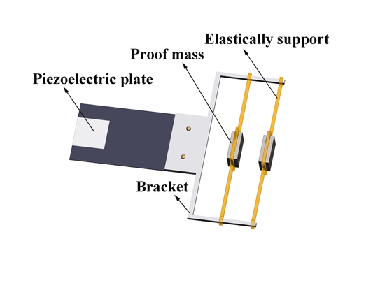
Figure 1 illustrates a schematic of the proposed PVEH. The device was remodeled from a conventional fiberglass cantilever, which constituted main structure stiffness of the device. A U-shaped bracket, made of aluminum alloy (Grade 6050), was mounted at the cantilever free end, whose two protrusive arms acted as the base for the elastically supporting masses. Considering the deformation of cantilever beam, the elastic range of rubber bands and the weight of proof masses, the number of elastic supports was set to two. Two uniform Fe proof masses (Grade Q235A) were attached to the middle of the rubber bands, and then tightened to the bracket with the distances of 5 mm and 25 mm from the end of protrusive arms. Each Fe proof mass weighed 10 g. A series of office rubber bands (3215, Deli, China) with different lengths but a similar section diameter of about 1.5 mm were selected to tune the device working frequency. A PZT-5A piezoelectric plate was bonded onto the cantilever end with a 90 μm-thick adhesive layer. The main dimensions of each component are shown in Table 1, and the distance between the two bracket arms was set at 100 mm.
The proposed PVEH was modeled by the lumped parameter method [18,19], and the device was equivalent to a mass–spring-damping system shown in Figure 2. Let u0, u1, u2, u3 be displacements of the exciter base and masses under external excitation, respectively. The primary system was composed of the primary effective mass m1, an effective spring k1, and a damper c1, and each secondary system consisted of a separate effective mass (m2, m3), a spring (k2, k3) and a damper (c2, c3). The primary mass m1 can be considered as the sum of all secondary masses (m2 + m3) concentrated at the free end of primary beam [20]. Then, the relative displacement between the exciter, primary mass and secondary mass can be expressed as,
x = u 1 u 0 ,   y 1 = u 2 u 1 , y 2 = u 3 u 1 .
Thus, the motion governing equations of proposed PVEH can be written as:
{ p = 1 3 m p x ¨ +   c 1 x ˙ +   k 1 x + θ V +   p = 2 3 m p y ¨ p 1 +   p = 1 3 m p u ¨ 0   =   0 m 2 y ¨ 1 +   c 2 y ˙ 1 +   k 2 y 1 =     m 2 x ¨   m 2 u ¨ 0 m 3 y ¨ 2 +   c 3 y ˙ 2 +   k 3 y 2 =     m 3 x ¨   m 3 u ¨ 0 θ x ˙ +   C p V ˙ +   V R l   =   0
where Cp and θ are the capacitance and electromechanical coupling coefficient of the piezoelectric plate, and V is the voltage generated by the piezoelectric plate at the load resistor Rl [21]. Let μ = m2/m1, and m2 = m3, in the proposed structure. Then, the generated dimensionless voltage across Rl can be obtained by solving Equation (1) as [22]:
| V ˜ | = | ( 1 + 2 μ   +   μ Ω 2 ( 1 α 1 2 Ω 2 + j 2 ζ 2 α 1 Ω + 1 α 2 2 Ω 2 + j 2 ζ 3 α 2 Ω ) ) ( 1 ( 1 + 2 μ ) Ω 2 + j 2 ζ 1 Ω μ Ω 4 ( 1 α 1 2 Ω 2 + j 2 ζ 2 α 1 Ω + 1 α 2 2 Ω 2 + j 2 ζ 3 α 2 Ω ) ) j r Ω + 1 j r k e 2 Ω + 1 |
where the dimensionless parameters are,
α 1 = ω 2 ω 1 ,   α 2 = ω 3 ω 1 ,   Ω = ω ω 1 ,   r = ω 1 C p R l , k e 2 = θ 2 C p k 1 .
Here, α1 and α2 are the frequency ratio between the primary system and the secondary system, Ω is the normalized frequency. ω is the excitation frequency, ω1ω3 are the natural frequency of each system, ζ1ζ3 are the damping ratio, r is the dimensionless time constant, and ke is the alternative electromechanical coupling coefficient.
Assuming a loaded resistor of 500 kΩ, the dimensionless voltage versus frequency curve is obtained with empirically determined variables [23]. It can be seen from the curve in Figure 3 that the proposed PVEH featured two distinct peaks in the frequency range of 0–20 Hz, and the second peak, originating from the primary cantilever, produced a higher output voltage.
Further investigation on the effect of the stiffness of elastic supporters was conducted by changing the values of k1 and k2 (k1 = k2 = k for the proposed scheme) in Equation (2), and the results are shown in Table 2. A longer rubber band processed a smaller k, and then slightly lowered the corresponding output voltage, which is indicated by the obtained trend in Table 2.

3. Results and Discussion

The experimental setup for evaluating the device characteristics is shown in Figure 4, and the enlarged inset presents the prototype of the proposed PVEH. In the tests, the PVEH was installed onto the exciter, which was driven by a series of sinusoidal signals generated by the function generator and amplified by the power amplifier. The accelerometer was used to monitor the applied acceleration, and the outputs of the proposed PVEH and accelerometer were recorded by the oscilloscope. All tests were conducted indoors at room temperature of about 25 ℃.
In order to verify the effect of the elastic supporters used, several rubber bands with varied lengths, inducing different supporting stiffness coefficient, were selected, and their parameters are presents in Table 3. Moreover, a metal supporter (supporter 4 in Table 3) and a conventional cantilever PVEH were also tested to more comprehensively evaluate the promoted structure. The physical prototype of supporter 4 is shown in Figure 5. The conventional cantilever PVEH had a length of 105 mm and a width of 40 mm. Figure 6 shows the comparison of experimental results under an exciting acceleration of 1 g (g = 9.8 m/s2). As can be seen from Figure 6, the devices with elastically supported masses featured evident promotion in resonance frequency, whose value turned from 16.5 Hz in traditional beam to 8.9 Hz in device with supporter 3, exhibiting a decline of 46%. Moreover, the generated peak voltage also receives a 1.47× increase, from 19.6 V to 28.8 V. Meantime, an additional resonance peak was generated near 5 Hz with an open-circuit voltage above 9.6 V, which was induced by the resonance of elastically supporting masses. The obtained promotion obviously depended on the utilized supporter. The short band (supporter 1), processing higher stiffness, caused less of an effect in the frequency than the softer bands, which can be further verified by the comparison between the metal and elastic supporters. The resonant frequency of support 3 changed 57.3% compared to support 4, which proves that replacing rubber band could easily adjust the resonant frequency of the structure. It can be inferred that the proposed structure can resonate at any point between 8.9–14 Hz by controlling the length of the rubber band.
Then, a further experiment was conducted to investigate the influence from excitation amplitude. Too large a deformation may cause nonlinearity to the behavior of rubber band, which will change the structural stiffness coefficient and ultimately affect the device frequency. Four different excitations with the acceleration amplitudes of 0.5 g, 1 g, 1.5 g and 2 g were applied to the PVEH, and the supporter 1 was chosen to construct the first test, who used the shortest band and had been greatly tensioned before excitation. The maximum acceleration was determined by considering the acceleration levels from everyday applications [24]. It can be seen from the results shown in Figure 7 that the device maintained its resonant frequency under the varied excitation with a maximum frequency drift of 0.3 Hz. Thus, the proposed PVEH features favorable performance stability and deals with the daily vibrations well.
Then, the output power of the proposed PVEH with supporter 1 and metal supporter was tested under a 1 g excitation. Since the second resonant peak possessed most of the harvested energy, the power investigation targeted at the second resonant point. Different resistors were connected to the device to find the best matching resistance corresponding to the vibration frequency. As it can be seen from Figure 8, the elastically supported scheme had a maximum output power of 1.417 mW with an optimized load of 410 kΩ, while the metal supported one produced a power of 0.758 mW with a load of 380 kΩ. Benefiting from the introduction of the elastic supporter, the proposed PVEH significantly improved the generated power by more than 87%.

4. Conclusions

In this study, two elastically supported masses were introduced into the cantilever-based piezoelectric vibration energy harvester to improve the harvesting efficiency, making it suitable for the low frequency vibrations in daily activities. The proposed prototype evidently declines the resonant frequency originating from the conventional cantilever configuration, and achieves two resonant peaks above 9.6 V in the range of 0–20 Hz. The utilization of common office elastic bands makes it very convenient to tune and control the device dynamic characteristic. We achieved a maximum resonance frequency adjustment of 57.3% in the experiment, and it is possible to get better results by continuing to adjust the length of the rubber band.

Author Contributions

M.Z., H.W. and B.L. conceived and designed the experiments; H.Q. performed the experiments; Y.L., B.L. and W.Z. analyzed the data; H.W. and M.Z. contributed analysis tools; and Y.L. and B.L. wrote the paper.

Funding

This research was supported by the National Natural Science Foundation of China (No. 61801357, No. 51505358).

Conflicts of Interest

The authors declare no conflict of interest.

References

  1. Alameh, A.H.; Gratuze, M.; Elsayed, M.Y.; Nabki, F. Effects of proof mass geometry on piezoelectric vibration energy harvesters. Sensors 2018, 18, 1584. [Google Scholar] [CrossRef] [PubMed]
  2. Kubba, A.E.; Jiang, K. Efficiency enhancement of a cantilever-based vibration energy harvester. Sensors 2013, 14, 188–211. [Google Scholar] [CrossRef] [PubMed]
  3. Savarimuthu, K.; Sankararajan, R.; Roji M., A.M. Design and analysis of cantilever based piezoelectric vibration energy harvester. Circuit World 2018, 44, 78–86. [Google Scholar] [CrossRef]
  4. Yang, Z.; Zhou, S.; Zu, J.; Inman, D. High-performance piezoelectric energy harvesters and their applications. Joule 2018, 2, 642–697. [Google Scholar] [CrossRef]
  5. Dhote, S.; Li, H.; Yang, Z. Multi-frequency responses of compliant orthoplanar spring designs for widening the bandwidth of piezoelectric energy harvesters. Int. J. Mech. Sci. 2019, 157–158, 684–691. [Google Scholar] [CrossRef]
  6. Nabavi, S.; Zhang, L. Nonlinear multi-mode wideband piezoelectric mems vibration energy harvester. IEEE Sens. J. 2019. [Google Scholar] [CrossRef]
  7. Zhou, Z.; Qin, W.; Du, W.; Zhu, P.; Liu, Q. Improving energy harvesting from random excitation by nonlinear flexible bi-stable energy harvester with a variable potential energy function. Mech. Syst. Signal Process. 2019, 115, 162–172. [Google Scholar] [CrossRef]
  8. Kathpalia, B.; Tan, D.; Stern, I.; Erturk, A. An experimentally validated model for geometrically nonlinear plucking-based frequency up-conversion in energy harvesting. Smart Mater. Struct. 2018, 27, 015024. [Google Scholar] [CrossRef]
  9. Fan, K.; Chang, J.; Chao, F.; Pedrycz, W. Design and development of a multipurpose piezoelectric energy harvester. Energy Convers. Manag. 2015, 96, 430–439. [Google Scholar] [CrossRef]
  10. Luo, C.; Xia, M.; Wang, Y.; Li, P.; Hu, J.; Li, G.; Jiang, H.; Zhang, W. A multiple vibration modes separation technique based on 3*5 element energy harvester array: Frequency, bandwidth adjustment, and electrical characterization. IEEE Sens. J. 2017, 17, 6378–6384. [Google Scholar] [CrossRef]
  11. Wang, H.; Hu, F.; Wang, K.; Liu, Y.; Zhao, W. Three-dimensional piezoelectric energy harvester with spring and magnetic coupling. Appl. Phys. Lett. 2017, 110, 163905. [Google Scholar] [CrossRef]
  12. Cao, S.; Liu, L.; Zheng, J.; Pan, R.; Song, G. Modeling and analysis of galfenol nonlinear cantilever energy harvester with elastic magnifier. IEEE Trans. Magn. 2019, 55. [Google Scholar] [CrossRef]
  13. Aldraihem, O.; Baz, A. Energy harvester with a dynamic magnifier. J. Intell. Mater. Syst. Struct. 2011, 22, 521–530. [Google Scholar] [CrossRef]
  14. Zhou, W.; Penamalli, G.R.; Zuo, L. An efficient vibration energy harvester with a multi-mode dynamic magnifier. Smart Mater. Struct. 2012, 21, 015014. [Google Scholar] [CrossRef]
  15. Seo, M.-H.; Choi, D.-H.; Kim, I.-H.; Jung, H.-J.; Yoon, J.-B. Multi-resonant energy harvester exploiting high-mode resonances frequency down-shifted by a flexible body beam. Appl. Phys. Lett. 2012, 101, 123903. [Google Scholar] [CrossRef]
  16. Kim, I.-H.; Jang, S.-J.; Jung, H.-J. Design and experimental study of an l shape piezoelectric energy harvester. Shock Vib. 2017, 2017. [Google Scholar] [CrossRef]
  17. Sun, S.; Tse, P.W. Modeling of a horizontal asymmetric u-shaped vibration-based piezoelectric energy harvester (u-vpeh). Mech. Syst. Signal Process. 2019, 114, 467–485. [Google Scholar] [CrossRef]
  18. Zhang, H.; Ahmadi, M. Resonance tuning of a multi-piezoelectric bimorph beams energy harvester connected by springs. Ferroelectrics 2014, 460, 34–48. [Google Scholar] [CrossRef]
  19. Zhang, H.; Afzalul, K. Design and analysis of a connected broadband multi-piezoelectric-bimorph-beam energy harvester. IEEE Trans. Ultrason. Ferroelectr. Freq. Control 2014, 61, 1016–1023. [Google Scholar] [CrossRef]
  20. DuToit, N.E.; Wardle, B.L. Experimental verification of models for microfabricated piezoelectric vibration energy harvesters. AIAA J. 2007, 45, 1126–1137. [Google Scholar] [CrossRef]
  21. Sodano, H.A.; Park, G.; Inman, D.J. Estimation of electric charge output for piezoelectric energy harvesting. Strain 2004, 40, 49–58. [Google Scholar] [CrossRef]
  22. Toyabur, R.M.; Salauddin, M.; Park, J.Y. Design and experiment of piezoelectric multimodal energy harvester for low frequency vibration. Ceram. Int. 2017, 43, S675–S681. [Google Scholar] [CrossRef]
  23. Tang, L.; Yang, Y.; Wu, H. Modeling and experiment of a multiple-dof piezoelectric energy harvester. Proc. SPIE 2012, 8341, 83411E. [Google Scholar]
  24. Yildirim, T.; Ghayesh, M.H.; Li, W.; Alici, G. A review on performance enhancement techniques for ambient vibration energy harvesters. Renew. Sustain. Energy Rev. 2017, 71, 435–449. [Google Scholar] [CrossRef] [Green Version]
Figure 1. Schematic of the proposed piezoelectric vibration energy harvester (PVEH).
Energies 12 02207 g001
Figure 2. Equivalent mechanical model of the proposed PVEH.
Energies 12 02207 g002
Figure 3. Dimensionless voltage versus frequency curve.
Energies 12 02207 g003
Figure 4. Diagram of experimental setup.
Energies 12 02207 g004
Figure 5. Physical prototype of supporter 4.
Energies 12 02207 g005
Figure 6. Open-circuit voltages of various supported.
Energies 12 02207 g006
Figure 7. Open-circuit voltages of various excitation.
Energies 12 02207 g007
Figure 8. Output voltages and powers of the elastic support and rigid support.
Energies 12 02207 g008
Table 1. Main dimensions of each component.
NameLength (mm)Width (mm)Thickness (mm)
PZT2019.50.2
Cantilever beam80400.5
Bracket401000.8
Table 2. Corresponding relationship between the dimensionless voltage and the effective spring, k.
k (N/m)610141822
dimensionless voltage1.81.92.22.63.3
Table 3. Support parameters.
TypeMaterial of SupportLength
supporter 1rubber band90 mm
supporter 2rubber band130 mm
supporter 3rubber band170 mm
supporter 4Al alloy of 6050100 mm