1. Introduction and State of Art
Development of a new wind turbine type is a challenging topic, because there is obvious responsibility offering a new product. The market for small wind turbines is very large with great number of innovative concepts. There is certain skepticism by customers in choosing wind turbines of new concepts, because usually information provided is incomplete and therefore not reliable. In order to avoid any confusion, the authors of this paper, presenting a new wind turbine, decided to provide a full scope of data, starting from required wind turbine functionality, presentation of developed turbine construction, numerical validation of the wind turbine operation and effectiveness, experimental analysis, and prototype manufacturing and testing.
Such set-up of the paper drives towards many difficulties. First of all many aspects have to be presented and discussed and secondly there is no space in one paper to discuss all issues in sufficient depth to obtain high scientific quality of the paper.
In spite of these difficulties the authors have tried to include all aspects of turbine development to introduce new turbine type, which is patented and validated. The important aspect of the paper is that the new concept of a wind turbine is not only presented but the results of demonstrators are also provided.
When considering the topic of wind energy one is usually referring to turbines with a large output which are mostly seen as a modern feature of the landscape. The development of this technology over the last three decades has led to one dominating turbine type, which is characterized by a horizontal axis three-bladed rotor. The choice of this wind turbine type results from optimizing the costs, including the implementation and the effectiveness of energy production. One of the important features of this wind turbine type allows obtaining a rotor with a minimum blade projection area, relative to the blade swept zone. This rotor type uses the lift force for turbine propulsion. The blade is passing the air at a much higher velocity than the wind velocity. Thanks to this, the blade chord may be kept short and the turbine blade is very slim. The rotor weight can be minimized in this way. It is also important that the aerodynamic forces on the stopped rotor at heavy winds are small, owing to the small projection area of the blade. Usually blades can be also pitched to the wind direction, minimizing the blade drag.
There are however technical consequences of choosing this wind turbine type, at small and at high winds. On one hand, the small effective area of the turbine blades causes difficulties at the start-up of the turbine operation at small winds. Such a turbine starts up slowly with a very small momentum delivered by the rotor. On the other hand, using the lift force may result in over-spinning at high winds, or at the loss of rotor loading. Over-spinning leads to a very high speed of rotation which may cause rotor disintegration. Therefore, it is necessary to stop the turbine at winds higher than about 20 m/s. A strange feature of a horizontal rotor (HAWT) is, that no energy is produced when the winds are very strong.
On the occasion of the World Small Wind Conference held during Intersolar Europe in Munich (Germany), the WWEA (World Wind Energy Association) released the global small wind statistics. The Summary of the 2017 Small Wind World Report indicates that 2015 was one of the most challenging years for the small wind turbine industry in the recent years. As of the end of 2015, a cumulative total of at least 990,000 small wind turbines were installed worldwide. This is an increase of 5% (8.3% in 2014) compared to the previous year, when 945,000 units were registered. It means that several million families are getting power from small wind turbines worldwide. The recorded small wind capacity installed globally has reached more than 945 MW as of late 2015. This is growth by 14% compared to 2014, when 830 MW were registered. In 2012, 678 MW were installed. China accounts for 43% of the global capacity, the USA for 25%, the UK for 15%, and Italy for 6.3% [
1].
Small wind turbine market is increasing by 5% each year. Several million families are getting power from small wind turbines worldwide. The American market of small wind turbines is the largest market in the world, and it is supplied by about 50 American companies which at the same time export 40% of their products. The largest company producing small wind power stations with the electric power output of 0.4–3 kW has operated since 1987 and produces 15,000 installations per year. They have sold 100,000 turbines in 120 countries [
1].
In general the small wind power industry refers to wind turbines which generate up to 10 kW of electric power, but the range which is the most interesting is limited to about 3 kW. This output range will become most common, as 3 kW of electric power makes a remarkable contribution to the power balances of large households and, what is more, can fully meet the power needs of holiday and recreation cottages.
There is already a remarkable list of low-power windmill sellers. However, the problem here is the installation price which is still very high. Another problem is that the offered windmills are designed for wind speeds ranging between 12 and 14 m/s. Such strong winds blow very rarely, and windmills useful in real conditions are to be designed for lighter winds, ranging between 6 and 8 m/s. It is also noteworthy that the chances of success will become realistic only when the installation costs are reduced. It is believed that the present market of new materials used in windsurfing, kite surfing, hang gliding and paragliding provides wide opportunities for designing and building extremely lightweight structures, ensuring considerably reduced costs.
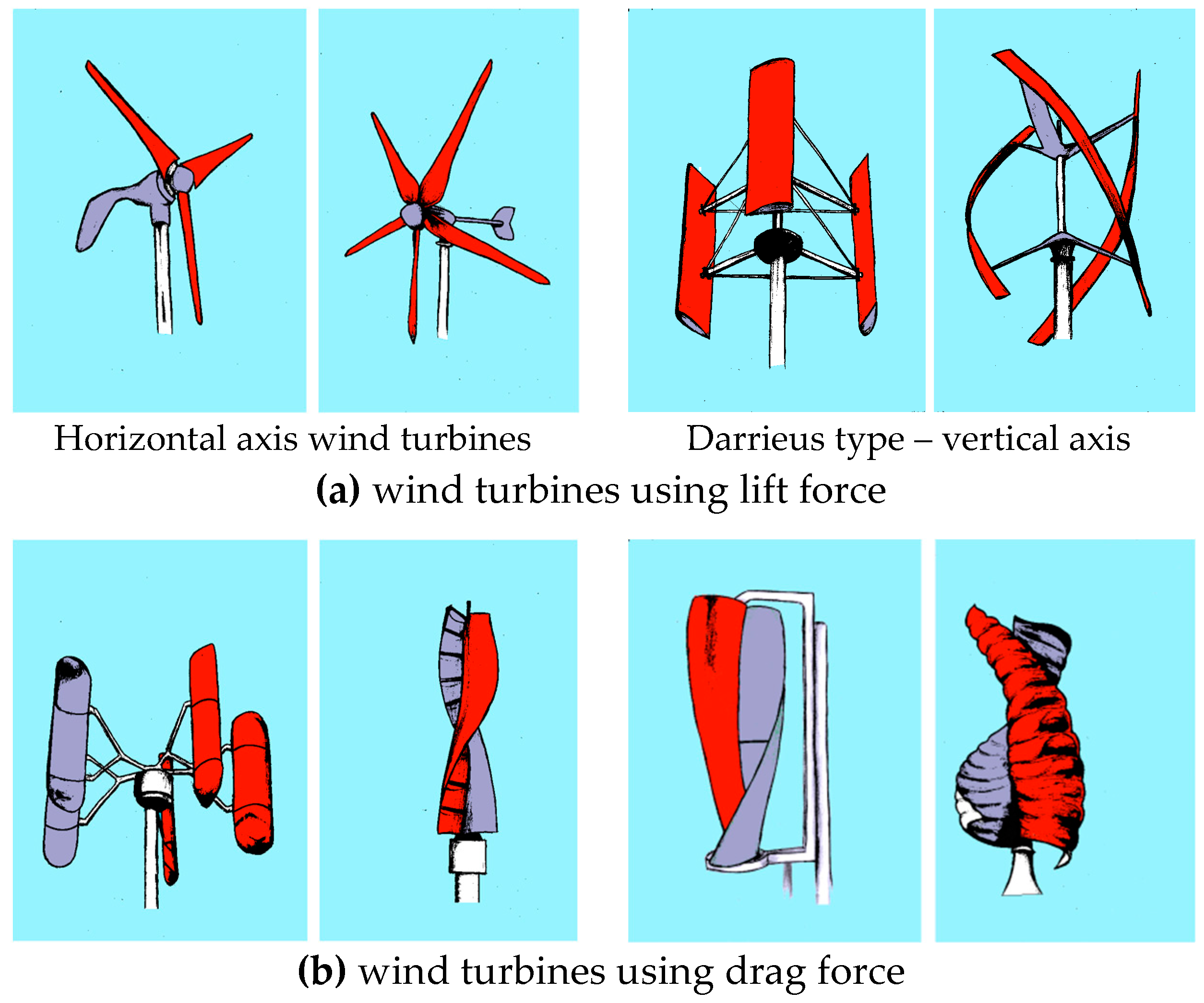
A characteristic feature of this turbine size sector is that there is no convergence of the turbine design to a single type. Therefore, all possible turbine types are found on the market. First of all, it should be pointed out that there are turbines using lift forces and other using drag forces. The examples of these turbines are presented in
Figure 1 below.
Wind turbines using the lift force are distinct by the fact that the lifting blade is moving with a much higher velocity than the wind itself. The blades in such wind turbines (
Figure 1a) are slim. In the case of wind turbines using the drag force (
Figure 1b), the blades move slower than the wind, to be propelled. The only way to increase the forces on the rotor is to use a larger size of the blade area. Therefore, one can notice (
Figure 1b) that such wind turbines cover nearly the whole rotor projection area. A typical structure for this wind turbine type is the Savonius rotor (
Figure 1b, right side).
Very high winds induce negative effects for both types of wind turbines, but of a different nature:
Lift force wind turbines are endangered by over-spinning at high winds which may lead to the destruction of the rotor by centrifugal forces. They need a brake to stop the rotor, it follows that no energy is produced at strong winds.
Drag driven turbines produce strong aerodynamic forces at extreme wind conditions. This requires a very strong turbine and a support structure, leading to heavy weight.
The above feature is the reason why drag driven turbines have not found their way to application at large turbine sizes.
There is no danger however, of over-spinning and turbine destruction. Drag driven wind turbines are much safer than lift driven turbines.
At small winds there are also characteristic features, different for both turbine types:
Lift force driven turbines, due to the small area of blades, startup with difficulty with small torque on rotors (
Figure 1a).
Drag driven turbines, due to the large active area of the rotors start at small winds with a high torque (
Figure 1b).
The above described characteristic features of different wind turbines (shown in
Figure 1) can be illustrated by the diagrams presented below in
Figure 2 and
Figure 3 [
2].
These are shown by the two main non-dimensional coefficients:
power coefficient - ,
torque coefficient - ,
These figures are only an illustration of the typical wind turbine features.
The characteristic curves of the power coefficient are presented in
Figure 2 for three typical turbines: Savonius, Darrieus and HAWT-3 with three blades. The Betz limit is shown as a reference (the black horizontal dotted line in
Figure 2) indicating the upper limit which can hardly be reached by any of the wind turbines. In this diagram it is clearly displayed that the turbines using the lift force develop the highest power at a high rotational speed where the TSR is about 4–5 and the turbine effectiveness reaches the level of 30–40%. A Savonius turbine reaches the maximum power at the TSR just below 1. The diagram also shows that the obtained power from a Savonius rotor is twice lower than in the case of lift driven turbines. However, in reality many HAWT and Darrieus turbines do not deliver such good performance and many products offered on the market are little above c
p > 0.2. It also follows from this diagram that the maximum rotation by the loss of load for a Savonius rotor is below TSR < 2. For lift driven turbines TSRmax goes up even close to 10, what may be destructive for the rotor in many cases.
An additional very important aspect is shown in
Figure 3. A Savonius rotor delivers very high moment at a low rotation speed. This is much higher than produced by a HAWT. For this reason, drag driven turbines start much better at low winds. The above presented features of various wind turbines should be helpful in choosing the wind turbine type by the investor. In this paper it is viewed from the perspective of a wind energy user with relatively small winds, between 4–7 m/s when the energy of wind is not more than 1000 kWh/m
2/year. It is therefore important that the wind turbine starts up and produces a high torque on the rotor at small winds. Such characteristic is provided by drag driven wind turbines.
It should be also mentioned here that in the case of a horizontal rotor (HAWT) the whole area swept by the blades is delivering propulsion. In case of vertical axis drag driven wind turbines (VAWT) the blades are moving against the wind on one side of the rotor, reducing the total generated power. Due to this feature the energy production by a VAWT is less than the production by a HAWT. If the turbine effectiveness or cost are the priority it is reasonable to choose the lift driven turbine type. The most important feature however, necessary for small size wind turbines, which are to be used in a close vicinity of buildings and people, is safety. One should avoid such wind turbines that may over-spin and be destroyed by centrifugal forces. This aspect suggests choosing the drag driven turbines. It is therefore why our interest went towards the Savonius rotor type.
The low effectiveness of the Savonius rotor makes it necessary to look for its improvement. Several researchers have tried to increase this effectiveness by a number of methods. Sun et al. [
3] and Shigetomi et al. [
4] resolved that the interaction of more than one turbine working site by site increased the power coefficient. Many authors have studied the classical Savonius turbine, finding maximum power coefficients in the range of 0.10–0.25 and focusing their interest on a low aspect ratio, which appeared to be the best choice. The few suggested designs for the Savonius rotor were studied by Tahani et al. [
5] where the performance and the discharge flow rate were reported for each model. An experimental validation test with numerical simulations performed by Driss et al. [
6] revealed an improvement of the fluid-flow circulation in the incurved Savonius rotor in comparison with a circular one. In these situations it is possible to detect some overlap flows that rise the pressure on the drive side. Additional common phenomenon with general agreement in literature is the periodic behavior of the torque angular distribution, with a periodicity identical to the amount of rotor blades [
7]. Some review articles have tried to recapitulate many numerical and experimental works carried out [
8,
9]. In the case of large output wind turbines HAWT the possibility of wind turbine improvement is much smaller. It is mostly small modifications involving the flow control that are developed and investigated [
10,
11,
12,
13,
14].
Among variety of new turbine ideas it is good to mention vertical axis twin rotor solutions. There are three patented ideas [
15,
16,
17] with two rotors, close to each other, set transverse to the wind direction. The retreating blades are shielded from the wind by a fairing in a shape of a wing or a diamond. So, this is like a streamwise object with rotor blades sticking out from the external parts on both sides. The characteristic feature of these twin rotor constructions is that in the central part a shield is preventing that the wind is flowing towards the blades moving upstream (
Figure 4).
There are also ducted concepts, where two vertical rotors are built into a duct. Some are patented [
18,
19,
20]. Different methods of shielding the retreating blades are proposed. In all these solutions the size of the box or external reach of the rotors is fixed.
It is difficult to find papers concerning wind turbines of variable size. Existing concepts concern mainly a Darrieus type of wind turbine. Such ideas are presented in Fadil et al. [
21] and by Urbahs [
22]. The supports of blades can increase their length at low winds and become shorter at strong winds. Thanks to this function the wind turbine has a larger diameter at small winds and smaller diameter at strong winds. Such mechanisms have not been developed for drag driven wind turbines. This is mainly due to the fact that these type of wind turbines cover nearly whole air stream and it is difficult to move large surfaces during turbine operation.
There are also hybrid solutions which change wind turbine configuration between a shape which is modeling Savonius rotor for small winds and for high winds it transforms to a multi-blade Darrieus type rotor [
23]. There are also other concepts as shown in [
24].
2. Innovative Wind Turbine Concept
As was concluded in the introduction, the choice of the Savonius turbine type is advantageous for small winds and provides high safety. Nevertheless, this choice is not very favorable as the effectiveness (Cp) of this wind turbine type is rather low at a level of about 20% while the effectiveness of a HAWT can reach even 30%. There is also another problem with the VAWT using the drag force, it has to have a very stable structure allowing it to withstand strong winds. This is the reason why the wind turbine and its support structure are heavy.
The application of a Savonius rotor calls for innovative solutions to improve its effectiveness and reduce the weight. One very obvious idea is to shield this side of the rotor at which the blades are moving against the wind, as shown in
Figure 5. The shielding allows directing the excess air onto the active side of the rotor, which is responsible for propulsion. The implementation of such a solution should improve the effectiveness of the system. Nonetheless, it should be emphasized here that the shield has to be always directed against the wind. It means that the independence of the turbine operation from the wind direction is lost in this application. In order to obtain a simple mechanism of setting up the turbine against the wind, the system shown in
Figure 5 should be doubled and the apex of the shields should be mounted on the mast, as shown in
Figure 6. The proposed system suggests that rotors are mounted on the shielding plates which are directing the wind towards the rotor’s propulsion side. In this new twin-rotor configuration one large Savonius rotor is substituted by two small rotors. This is a method to reduce the weight of the rotors which are the essential parts of the new wind turbine.
This new idea essentially may be set-up as a fixed distance between rotors, with an adequately chosen angle between the guiding plates [
25]. The system presented in
Figure 6 shows the design which may be built in a way to reduce the mass of the turbine and the support structure. It has been proven that the best effectiveness may be obtained with the ratio of guiding plate length to rotor diameter equal to 1.5. Rotary mounting of the shielding plates on the mast may also allow independent movement of plates, and a variation of the distance between rotors [
26]. This feature allows increasing the size of the wind stream engaged by the wind turbine as shown in
Figure 7. It is obvious that the unfolded set-up (
Figure 7) should be used at small winds and the folded one (
Figure 6) at strong winds. The system of folding and opening of the wind turbine can be simply designed to be operated by aerodynamic forces acting against some tensioning mechanism. The new innovative wind turbine, presented here, introduces a new feature, which is the variation of the incoming air stream size during the wind turbine operation.
This new feature introduces a difficulty in comparison with other wind turbines, having a constant reference air stream size. In our solution the turbine size changes during the turbine operation at high wind speeds, which affects the turbine power output. Talking about effectiveness, it makes sense when one refers to the power of the air stream involved by the wind turbine. Hence, in the reference folded case (
Figure 6) it is stream “A” (marked in
Figure 7). In the unfolded case the reference stream is “B” (marked in
Figure 7). The size of “B” is here a direct result of the configuration indicated in
Figure 6. The effectiveness in these two cases, taking into account different air stream sizes is nearly the same. But the power production depends on the actual wind turbine area and the ratio is B/A = 2.3.
The opening angle is limited to avoid unstable behavior of the system. It has been proven that the maximum angle of the shielding plate inclination to the wind direction should not exceed 70° on each side. Experiments in a wind tunnel and on the existing prototypes have confirmed that the system with such an opening angle is still stable, up to very high wind velocities measured (20 m/s). Therefore, the folding of the system may safely take place at the planned 12–14 m/s or even at higher wind velocities.
In addition to looking at the actual size variation of the increased air stream, in the case of a new solution of a wind turbine (
Figure 6 and
Figure 7), one can show the rotor size change for a different inclination of the guiding plates for the same wind stream involved.
Figure 8 shows that in the case of a fully “open” (70°) innovative wind turbine the rotor size may be reduced by about five times. This should lead to significantly reduced investment costs, even when two rotors are used.
Having worked out the above new wind turbine concept it is valuable to make comment on its originality in comparison to existing solutions. Twin rotor concepts [
15,
16,
17] fix the rotors as close as possible to each other and separately a fairing element is preventing the wind to blow on the retreating blades. In our concept however, the rotors are mounted at the end of shielding plates, allowing the rotors to be of small diameter and providing possibility to change the distance between them.
The concept proposed in this paper, of guiding plates equipped with a rotor, allows for the first time to increase the size of the drag driven wind turbine.
3. Validation of Innovative Wind Turbine
The new turbine concept was validated numerically and experimentally. Numerical simulations were run using the ANSYS (Fluent) code based on the finite volume method. Generally, the governing equation system takes the following normal form:
where:
– the vector of conservative variables;
– the convective flux;
– the pressure (recoverable ) flux;
– the diffusive flux.
Applying the discretization method for solving this equation after integrating (1) over finite volume
and defining
as a discrete value of vector
in the centre of a finite volume, that has numerous boundary faces
with the nearby finite volume
,
, as a final point one gets
where
- is a discrete average value of vector
positioned in the centre of
;
is the mass matrix independent of time;
is the residuum in formla:
In the below, the numerical flux differs slightly from the physical fluxes . Variables are the conservative one at the right and left sides of a boundary face j. Usually, the form of the numerical fluxes depends on the precision of the reconstruction of the field on the left side and instantaneously on the precision of the reconstruction of the field on the right side .
Two configurations have been simulated. The first is a typical Savonius rotor alone and the other is Savonius rotor with a guiding plate, as shown in
Figure 7. Simulations are carried out in a streamwise box with inlet velocity condition and outlet pressure condition. Side walls of the box are inviscid walls and for plate with rotor a symmetry condition is used, as only half of twin rotor system is simulated. Unsteady calculations were carried out with a sliding mesh on the interface between rotating and stationary parts. This approach permits vertical structures to pass from the rotor to stationary domain. The numerical solution was obtained using the second-order upwind scheme. Central difference schemes were used for the diffusion terms. The SIMPLE method was applied to solve the coupling of pressure and velocity. The approach described above is similar to the ones used by other authors in [
4,
5,
6,
7,
8,
9,
27,
28,
29]. The second order k-omega turbulence closure was employed for the velocity field modeling. This closure has been usually applied in the simulations of turbulent flows and has been established to have the most accurate prediction of flows in Savonius-turbine applications [
8,
23,
30].
A total amount of 524,424 elements (Savonius) and 803,460 elements (rotor with a guiding plate) were used for meshing of these configurations in 2D approach. Good mesh quality is expressed by the value of minimum orthogonal quality 0.539 for Savonius case and 0.691 for twin-rotor one, values of maximum aspect ratio of cells are 4.81 and 3.93 respectively. For those meshes, the maximum values of y+ on the blades or shielding plates do not exceed 6.2 for speed of wind 10 m/s and for tip speed ratio 1.1. Slower air free stream conditions lead to reduced y+ values. Inlet boundary condition is defined as a uniform velocity with a turbulent viscosity ratio equal to 10 and a 5% of turbulence intensity, for all cases. There are typical values for these turbulence parameters. The transient numerical scheme uses a time step Δt that provides a turn of 1° of the blades for rate of the angular velocity for all cases and both types of turbines. The criterion of performing a maximum of 100 inner iterations at each time step were applied. In some cases, the convergence is accomplished earlier. A minimum amount of full three revolutions of rotors is simulated. Drag forces and torque are monitored for each side of two blades. The value of power (as the product of torque and rotational speed) is the result of averaging values from the whole cycle of periodic revolutions.
Draft simulations have shown that the optimal configuration of the new wind turbine is obtained when the guiding plate length equals L = 1.5 D, where D is the rotor diameter. The plate deflection angle significantly influences the innovative turbine, it may vary from 15° (case “A” in
Figure 6) to 70° (case “B” in
Figure 7). The effect of the wind turbine opening is presented in
Figure 9. The case of U = 8 m/s and the rotor speed coefficient of λ = 0.7 were chosen to illustrate the wind turbine operation. The rotor diameter in these particular sets of simulations was D = 0.38 m and the rotor height was 1 m. As it is shown in
Figure 9a the power produced by the rotor is increasing almost linearly with the increasing angle of the plate installation. This is connected with an increase in the reference air stream area, different for each value of the plate deflection angle.
This increase in the reference air stream width is taken into account in the definition of the wind turbine effectiveness in
Figure 9b. An important conclusion is obtained that the turbine effectiveness maintains the same level independently of the plate’s deflection angle. The level of the new configuration (plate + rotor) effectiveness is higher than for the Savonius rotor alone. It is only at small angle that the effectiveness becomes lower, due to the inter-rotor interference. This is actually a positive effect because the wind turbine is folded when it is necessary to reduce the power output. In consequence it should be emphasized that two small rotors are able to produce slightly more power than a large Savonius rotor of a corresponding width, as shown for example in
Figure 8, for 70° plate deflection angles.
A single Savonius rotor was simulated as a reference case and compared with the twin-rotor innovative concept for the wind velocity of 10 m/s and 70° opening angle. The general information presenting the dependence between the turbine effectiveness and the TSR (tip speed ratio) is shown in
Figure 10. The values of effectiveness seem to be high because no transmission and generator losses are included.
The Savonius rotor characteristics confirm the information from the literature. The maximum effectiveness and power are obtained for TSR = 0.85 and they are in compliance with the known Savonius rotor behavior. The obtained results [
31] confirm that the simulation methodology used is providing correct results for the analyzed type of flow. It is important to indicate that the effectiveness in
Figure 10 is referred to the incoming stream size which is “A” (
Figure 7) for Savonius and “B” for twin-rotor innovative wind turbines. Similar behavior of rotors in the Twin-Rotor Turbine as well as of the Savonius single rotor is a very important finding. It is also important that the new solution has higher effectiveness than the Savonius rotor alone. It also means that power generated in these two cases is proportional to A/B (
Figure 7). In other words, the power generated by two small rotors (
Figure 7) is 2.3 times higher than the power generated by a Savonius rotor. If the same size of both configurations were compared, namely for A = B (
Figure 8), the same power is obtained with a TRWT with two rotors of a diameter five times smaller than in the case of a single Savonius.
The rotor rotation speed (RPM) depends on the rotor diameter at the same wind velocity. Hence, at the same wind speed the maximum effectiveness for the innovative solution (as in
Figure 10) is obtained at five times higher RPM. This is a very advantageous feature of the new wind turbine from the point of view of electricity generation. Similar simulations were carried out for different wind speeds, but always for TSR = 0.85, assuming that this rotation speed is delivering maximum power [
31]. The obtained results are presented in
Figure 11. This proves that the increased effectiveness of the Twin-Rotor is maintained for the whole spectrum of wind velocities and is at the level of 27% (without mechanical and electric losses).
Finally it should be indicated that the effectiveness obtained by present numerical simulations for Savonius rotor, on the level of 23–25% is in good agreement with many literature data, cited in this paper. This good agreement helps to consider carried our simulations as reliable.
5. Validation of the Innovative Twin-Rotor Wind Turbine
Validation of a new wind turbine is a complex process because the unit is of a considerable size even for a small power output. With 20% of the TRWT effectiveness, a 1000 W turbine needs 5 m
2 at the wind velocity of 12 m/s. The wind tunnels usually cannot allow a larger model cross-sectional area than 10% of the test section. Having access to a wind tunnel of D = 5 m in diameter, it means that the wind turbine model cross-section cannot exceed 2 m
2. Therefore, even a 1 kW wind turbine of the type discussed here is too large. Unfortunately, drag force driven wind turbines have a large cross-sectional area that brings a limit to such a wind turbine size for wind tunnel testing. However, the aerodynamic investigations have always been undertaken in the small wind turbine research [
32,
33,
34,
35].
The prototype manufactured in our research was based on the rotor diameter D = 0.25 m. It was 3.3 m, high and 1.2 m wide in the open position (“B”,
Figure 7). The cross section of this prototype in the open position is close to 4 m
2. In spite of its large size this prototype was tested in a wind tunnel. The objective was to verify the functionality of the technical solutions responsible for the wind turbine rotation on a mast and the tensioning system responsible for opening the shielding plates. This testing was very useful and allowed improving the design of the prototype. The prototype was however too large to allow adequate measurements of the generated wind turbine power. This aspect had to be tested outdoors. The new wind turbine was mounted on the roof of the Institute’s building (
Figure 15).
The measurements, carried out in the natural environment, are a challenge in comparison to the wind tunnel testing. In a wind tunnel, there is a possibility to adjust the wind speed and keep it constant, during the application of different loadings. This allows a careful determination of the power curve for the adjusted wind speed. Such precise power curve measurements allow finding the maximum power for each wind velocity. These maximum values of power for each wind velocity constitute the power curve for the wind turbine. Therefore, wind tunnel measurements allow the determination of a wind turbine power curve with very good precision. Outdoors, there is no possibility to control the wind. The delivered data contains the instantaneous measurement of wind parameters and the wind turbine loading. The selection of the corresponding wind velocity, the extracted power and the rotor speed, are crucial for the power curve. Essentially it should be possible to construct the power curve P = f(TSR) for each chosen wind speed value. However, the wind gusts are the reason why a new parameter appears to be important, namely, the wind velocity gradient at the moment of measurement. Changes of wind in some open space locations may be slow and weak. In such a case it is possible to reconstruct the power characteristic of a wind turbine. Unfortunately, such good conditions happen very seldom. Mostly, the wind undergoes significant dynamic processes in which short periods of constant winds are very seldom. It is especially the case with wind turbines mounted in a built-up zone.
The issue related to the power curve determination is the method of extracting maximum power from the turbine. This means that one needs the knowledge how the turbine should be loaded at the actual wind value in order to extract the maximum power.
The operation of the prototype allowed practicing numerous algorithms for the turbine loading in order to gain the maximum power out of the wind turbine. The algorithms developed by us allowed obtaining the results presented in
Figure 16.
During the time of using the prototype it did not happen that the wind of 12 m/s was reached, therefore the folding of the shielding plates at the available wind speeds could not be observed. In order to observe the mechanism of wind turbine folding nevertheless, the limit was adjusted to about 8 m/s. Owing to this, the wind turbine folding was recorded several times. The prototype effectiveness was proven only for wind speeds below 8 m/s. The obtained measurement points are presented in the plot in
Figure 16.
The electrical power P was calculated as the product of instantaneous values of voltage U and current I: P[W] = U[V]∙I[A], with: U – voltage, I-current.
Both the voltage and the current were measured using transducers incorporated in the apparatus designed and built especially for our experiment. The relative error value is 1% for both of them. Using the principle of propagation of uncertainty for the product, if the voltage and current uncertainties are assumed to be random and independent, one obtains the uncertainty of
P to yield:
Taking into account the fact that both the measurements were performed using the same apparatus, it can be difficult to justify the assumption of the voltage and current uncertainties being random and independent. Therefore, it is safer to apply the total derivative estimation of the maximum relative error and obtain the relative value of the error of electrical power as follows:
The wind velocity is measured by a commercial sensor with 1% precision. In the diagram in
Figure 16 the error bars are not visible and are covered by the point markers. The lines of 20% and 30% of effectiveness are plotted in addition and show that the wind turbine effectiveness is within this range. This effectiveness is in relation to the stream width B (as in
Figure 7). One should emphasize that the loading of the presented prototype has not been optimized yet. Therefore, one could still expect further improvement in the energy production. Extrapolation of the results presented in
Figure 16 shows that the power of 800 W will be actually reached at 12 m/s, as expected.


