Article

Fireside Corrosion on Heat Exchanger Surfaces and Its Effect on the Performance of Gas-Fired Instantaneous Water Heaters

1
School of Civil Engineering, Chongqing University, Chongqing 400045, China
2
Joint International Laboratory of Green Building and Built Environments, Ministry of Education, Chongqing 400045, China
3
Key Laboratory of Three Gorges Reservoir Region’s Eco-Environment, Ministry of Education, Chongqing 400045, China
*
Author to whom correspondence should be addressed.
Energies 2019, 12(13), 2583; https://doi.org/10.3390/en12132583
Submission received: 5 June 2019 / Revised: 27 June 2019 / Accepted: 1 July 2019 / Published: 4 July 2019

Abstract

:
The heat exchanger in a gas instantaneous water heater is a thermal device used for heat transfer from the high-temperature flue gas to the low-temperature water. The fireside corrosion, due to the reaction of acidic condensate formed on the heat exchanger surfaces and its metallic material, is one of the major hazards for gas instantaneous water heaters. This paper focuses on identifying and quantifying the fireside corrosion on the surface of heat exchangers in gas-fired instantaneous water heaters. Durability tests lasting for 2000 cycles were undertaken for five gas-fired instantaneous water heaters, which were different in terms of the heat input and coating of heat exchangers. The corrosion deposits on the surface of the heat exchangers were surveyed by several methods. The results show that the corrosion deposit grew as the test duration increased. The fins of the heat exchanger with a lead coating had been corroded and copper was exposed. Cu4(OH)6SO4 was the main corrosion product of heat exchangers without a lead coating, whereas PbSO4 was the main corrosion product of heat exchangers with a lead coating. The experiments demonstrate that the corrosion rate decreased with the increase of the heat input. The experiments also show that the thermal efficiency of gas instantaneous water heaters decreased by 2.4% to 6% at the end of the test duration.

1. Introduction

The energy used for global building accounts for 35% of the total energy consumption [1]. Similar to the global energy consumption, the amount of building energy expense in China was 857 million tons of standard coal, accounting for 20% of the country’s total energy expense, in 2015, according to the statistics of the China Association of Building Energy Efficiency [2]. It indicated that the energy usage of urban residential and rural buildings was 320 million tons and 197 million tons, respectively. The BP statistical review of world energy stated that the global natural gas consumption contributed 23.4% of the total in 2017. Although, in China, the proportion of natural gas in primary energy consumption was only 6.7%, the growth of natural gas use was particularly strong, with a value of 15.1% [3]. Gas depletion has a share of around 30% in the depletion of energy resources in buildings [4].
Gas-fired instantaneous water heaters and stoves are the most important part of building energy consumption, in addition to the electricity. To improve the energy efficiency, many countries have a strict assessment of the energy cost and exhaust emission for water heaters and have established corresponding standards [5,6,7,8]. In China, energy efficiency grades of gas-fired water heaters are divided into three categories (Table 1). If the water heaters cannot achieve the lowest grades, they are prohibited in the market [7]. However, the water heaters are only sampled and graded before they are put on the market, without any monitoring or re-gradation during service.
The core part of an instantaneous gas-fired water heater is the heat exchanger, and corrosion is one of the most severe hazards to the heat exchanger, which always occurs in the service of the gas-fired instantaneous water heater. According to a survey in New Zealand, more than 90% of heat exchangers have some sort of fouling problem [9]. Globally, the economic loss due to corrosion amounts to more than US$4 trillion a year [10]. There are lots of corrosion costs every year in every country (Table 2) [10,11,12,13].
The fireside corrosion of heat exchangers is mainly due to the condensation of acids in the flue gas on the surface of metal [14,15]. Since gas normally contains a small amount of sulfur, which can be oxidized, sulfur trioxide (SO3) and sulfur dioxide (SO2) are usually formed during the combustion process. When the temperature of the heat transfer surface is lower than the sulfuric acid dew point temperature, the sulfuric acid vapor and water vapor condense on the surface of the heat exchanger, which will cause a corrosion issue [16]. Lampert et al. [17] have pointed out that an effective way to reduce the risk of corrosion is to keep the temperature of the exhaust gas above the acid dew point. Increasing the water vapor can also reduce corrosion, as well as sulfation [18]. Meanwhile, the presence of chlorides could greatly increase the corrosivity of the environment [19,20]. Khodamorad et al. [21] also concluded that the simultaneous presence of chloride and sulfide in the media hastens the SCC (stress corrosion cracking) failure in the heat exchanger plates. Some scholars have also analyzed the effect of sulfide on the corrosion of metal surfaces from a biological perspective [22]. In addition, the surface temperature of the heat exchanger has a great influence on the corrosion rate of the heat exchanger [16,19,23,24,25,26] and previous deposit accumulation called corrosion history can impact the future corrosion attack [27]. Corrosion and fouling of the heat exchanger not only reduce the efficiency of heat transfer, but also increase the temperature of flue gas and energy consumption, which then results in safety accidents and economic loss [28].
Although copper is a common material used in heat exchangers [29] due to its excellent properties of heat transfer and corrosion resistance in many atmospheric environments [30,31], there are still some problems, such as it is inability to resist corrosion in acid environments [32]. Therefore, many studies on corrosion-resistant material and corrosion inhibitors have been carried out [33,34,35,36,37]. Moreover, Gruber et al. developed an empirical function, which is able to reproduce the corrosion potential [38]. Kwangkook Jeong et al. developed a computer program for numerical simulations of sulfuric acid condensation in a flue gas condensing heat exchanger [39], both of which can assess the corrosion.
However, the characteristics of fireside corrosion during the actual operation remain unclear. In the current research, we aimed to identify and quantify the process of corrosion failure in the heat exchanger and assess its effect on the thermal performance of the gas-fired instantaneous water heaters in service. Several analysis methods are adopted, including visual inspection, scanning electron microscope/energy dispersion spectrum (SEM/EDS), X-ray diffractometry (XRD) and a calculation of the corrosion rate, thermal efficiency of the gas instantaneous water heaters and the experimental uncertainty.
In this paper, first of all, the corrosion mechanism of heat exchangers is analyzed theoretically. Then, the test methods are briefly described. Finally, the corrosive behaviors are characterized by the analysis methods mentioned above, comparing the effect of the corrosion on different gas-fired instantaneous water heaters, and investigating the measures for mitigating the fireside corrosion of heaters in the actual service.

2. Background

In a gas-fire instantaneous water heater, the gas is burnt in the combustion chamber and the high-temperature flue gas then flows through the fins and pipes of the heat exchanger, where cold water is heated. The water firstly flows through the pipes around the outside of the combustion chamber, and then enters the heat exchanger pipes, where it obtains heat from the flue gas in the combustion chamber and exchanger by heat conduction, convection and radiation. After exchanging heat with water, the flue gas is discharged from an exhaust pipe. Generally, the gas-fired instantaneous water heater is mainly composed of a burner, a combustion chamber, a heat exchanger, an air blower, some tubes and a control system. A schematic diagram of a gas-fired instantaneous water heater is shown as Figure 1. It is obvious that the heat exchanger plays an essential role in a water heater, and copper is widely used in the heat exchanger because of its high heat conductivity and excellent hot workability [31].
One of the major hazards of water heaters is the fireside corrosion of the heat exchanger, which is mainly caused by high-temperature oxidation and sulfation. The corrosion caused by the former is relatively weak due to the anti-corrosion layer on the metal surface.
Sulfation occurs when the temperature of flue gas drops to the acid dew point, and sulfuric acid condensate is then formed. Moreover, acidic substances can also be dissolved in the condensed water, forming acidic condensate. As a result, the heat exchanger may be corroded.
As is known, one cubic meter of natural gas (if it is regarded as methane) will produce 1.55 kg of water vapor after combustion. If the flue gas is cooled to a temperature below the dew temperature, water vapor will condense. In fact, H2S and other substances containing sulfur in natural gas will be converted to SO2 during the combustion process, and some of the SO2 will be further oxidized to SO3 in the excess air, which then combines with water vapor in the flue gas to form gaseous sulfuric acid [16,40]. In addition, CO, the production of imperfect combustion, can facilitate the formation of SO3 [41]. Gaseous sulfuric acid will condense into sulfuric acid mist when the temperature of the flue gas drops to a temperature below the acid dew point.
The heat exchanger will be seriously corroded when the sulfuric acid mist drips on its surface [42]. If the heat exchanger is coated with lead, then lead will be corroded and PbSO4 will be formed. When copper is exposed, the copper begins to be corroded and copper sulfate is formed.
Rather than a fixed value [43], the water dew point has a close relationship with the partial vapor pressure, gas composition and excess air coefficient in the flue gas. Assuming that the fuel burns completely, because of excess air, an excess air fraction is introduced into the combustion equation and the modified equation (Equation (1)) can be obtained. Through the volume proportion of each component in Equation (1), partial vapor pressure can be calculated as Equation (2). The corresponding water dew point can be deduced from Table 3.
CnHm + α(n + m/4)(O2 + 3.76N2) = nCO2 + (m/2)H2O + (α − 1)(n + m/4)O2 + 3.76α(n + m/4)N2.
Ps = [(m/2)/[n + m/2 + (4.76α − 1)(n + m/4)]] × 105.
Bahadori [45] proposed a simple-to-use predictive method to obtain a proper estimation of the flue gas acid dew point, which shows a great dependence on the fuel type, sulfur content in fuel and excess air coefficient. The computing approach is formulated in Bahadori’ work as shown in Table 4 and the relevant coefficients (A, B, C and D) have been reported in Table 5. The dew point decreases with the increase of the excess air coefficient and carbon content, in addition to the reduction of sulfur content.
The water vapor in the flue gas condenses on the surface of the heat exchanger. As long as the acid gases CO2, NO, NO2, SO2 and SO3 in the flue gas remain in the state of gas, instead of dissolving in the condensate, the heat exchanger will not be corroded. On the contrary, dilute acidic mixed solution composed of carbonic acid, nitric acid and sulfuric acid will corrode the heat exchanger. Generally, when the temperature of flue gas drops, it reaches the acid dew point of gaseous sulfuric and water dew point in turn, and then other acidic substances dissolve in the condensed water to form acidic condensed water.

3. Experimental Procedures

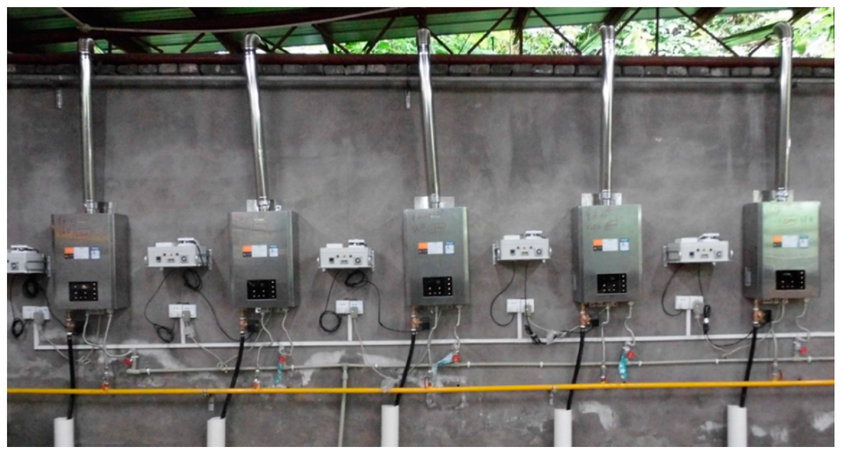
3.1. Establishment of the Test Platform

3.1.1. Test Samples and Gas Source

In order to investigate the fireside corrosion of the heat exchanger, a test platform was set up, as shown in Figure 2, where five gas-fired instantaneous water heaters with a mechanical exhaust were chosen for the tests. There were three different rated heat inputs as shown in Table 6. The five heat exchangers were identical apart from the coating and their detailed specifications are listed in Table 7. Among them, two of the heat exchangers (B and D) were plated with lead, and the others were free of any coating. The natural gas was supplied by the gas pipeline network in the metropolitan city Chongqing, and the composition of natural gas was measured and monitored by gas chromatographs at the gate station, as shown in Table 8. The tests were run for 2000 cycles. In each cycle, the heaters operated for one hour, including 15 min at the rated heat input, 35 min below the rated input (about 14 kW), and then 10 min of outage. The process of each cycle was controlled by a controller.

3.1.2. Test System

As shown in Figure 3, a test system includes water heaters, a gas flowmeter and a thermometer installed in the gas pipeline. Furthermore, a flue gas analyzer is installed in the chimney and close to the entrance to the chimney. Technical parameters of the test instruments are shown in Table 9.

3.2. Measurement Methods

The procedures of tests are as follows:
  • Fins of the outlet side of heat exchangers of the five gas-fired instantaneous water heaters were examined macroscopically without disassembly and recorded with a digital camera every 400 cycles;
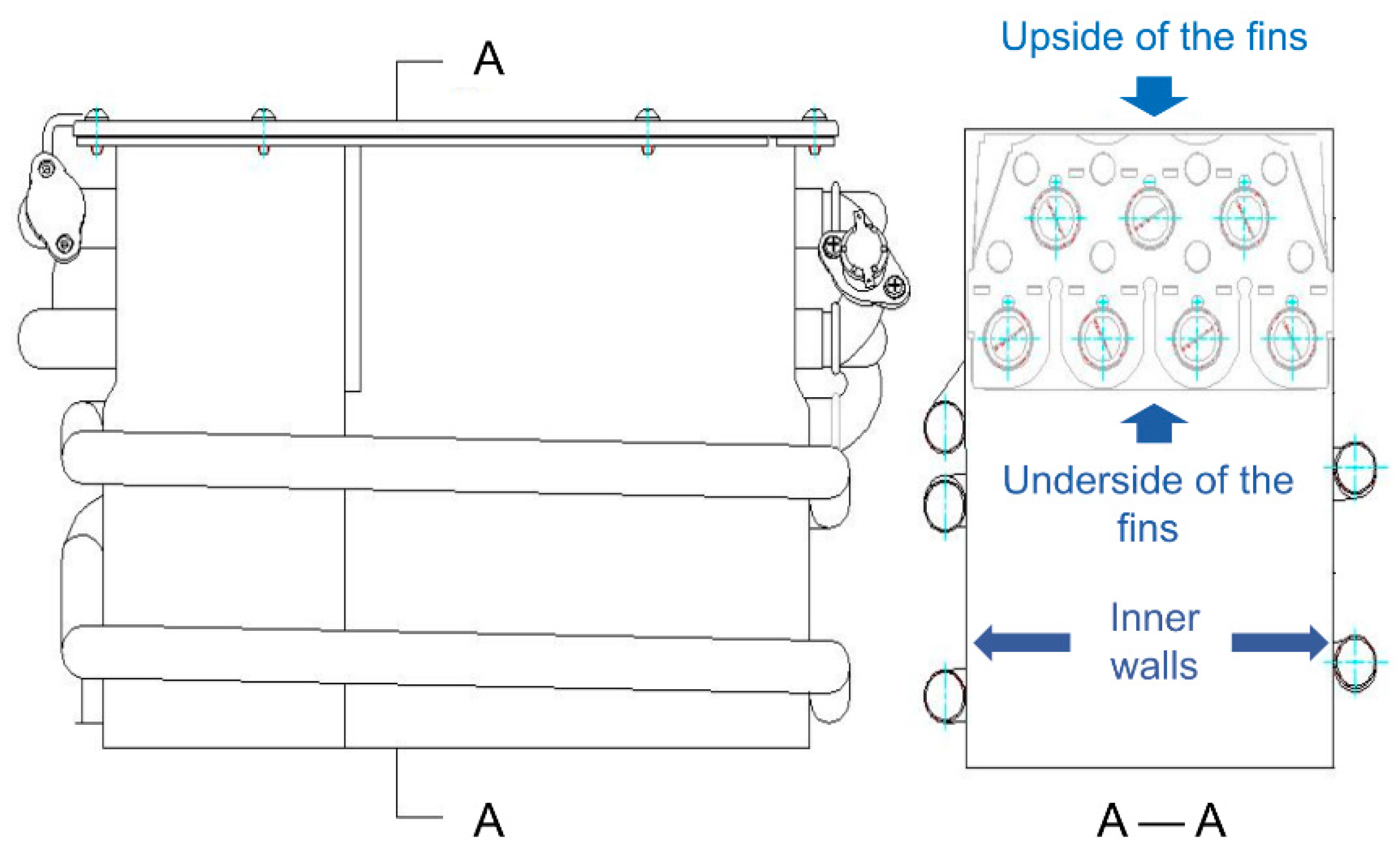
  • The water heaters were disassembled after 1000 and 2000 test cycles, the condition of the heat exchangers was observed, and corrosion products on the inner wall of the combustion chamber and gums of the fins were sampled. Figure 4 shows the section view of the heat exchanger and the estimated positions in the detection are marked on the map;
  • Corrosion samples were examined by SEM, EDS and XRD;
  • The heat exchangers were cleaned and the corrosion products were removed, and the weight loss of the heat exchanger was then measured after 2000 cycles, so the corrosion rate could be calculated.
The thermal efficiency of the five heaters was tested at 0 cycles, 1000 cycles, 1600 cycles and 2000 cycles based on the standard procedures and methods according to the Chinese national standard GB6932-2015 [6].
  • Before the test, the environmental parameters (such as temperature, atmospheric pressure, etc.) and the temperature of the inlet water were measured.
  • During the test, the water temperature should be measured by mercury temperature after 15 min of launching it in order to ensure stable combustion of the water heater. The current value of the gas flow meter should be recorded when gas flow measurement starts by using a stopwatch. The outlet pipe should be placed in the water tank and the measurement should be finished after 1.5 min.
  • The thermal efficiency of the gas-fired instantaneous water heater can be calculated as follows [6]:
    ηt = M × Cp(tw2tw1)/(V × Q1) × (273.15 + tg)/273.15 × 101.3/(Pamb + PgS) × 100.

4. Results and Discussion

4.1. Analysis of Results from Macroscopic Inspection

From the photos taken during macroscopic inspection, we can find changes in color and deposits on the upper surface of heat exchangers. It is obvious that different types of heat exchangers had different features of corrosion.

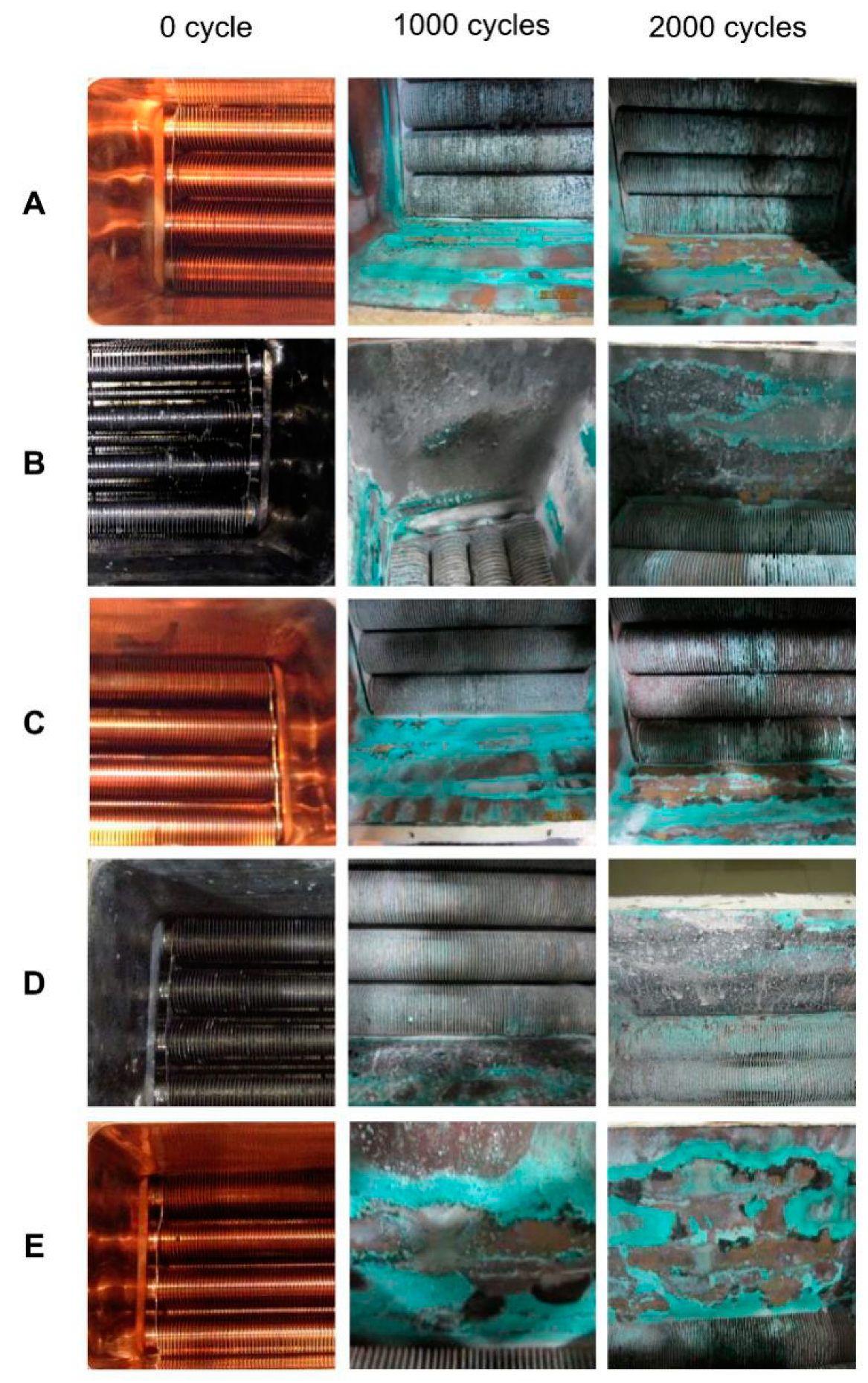
4.1.1. Macroscopic Inspection of Four Walls of Combustion Chambers

The macroscopic inspections of the four walls of the heaters are shown as Figure 5. At 1000 cycles, there were a large number of green solid deposits on the walls of the heat exchangers, mainly on the inner side of the joint between the walls and the water tubes. The products were distributed in strips, which, with many more attachments, were along the joint between the walls and the outer water pipes.
At 2000 cycles of tests, the green solid deposits on the walls of combustion chambers were more numerous than those at 1000 cycles and covered a greater area of the inner walls. Some of the deposits had dropped down onto the combustor. The coverage of corrosion products on the heat exchanger of E was wider than that of A and C, and its flaking condition increased evidently. At 2000 cycles, the coatings of heat exchangers B and D were peeled off and copper was exposed.

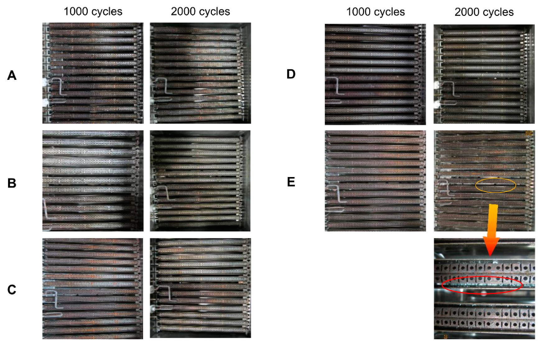
4.1.2. Macroscopic Inspection of the Underside of the Fins of the Heat Exchangers

Compared with the initial states, a large amount of gray solid deposit covered the underside of the fin of all heat exchangers at 1000 cycles. Figure 6 shows that gray corrosion products were accumulated in the gaps between fins.
At 2000 cycles, it was clear that the corrosion products on the fins were more numerous than those at 1000 cycles and some gaps between the fins were seriously blocked. The fins of the heat exchangers plated with lead had also been corroded so that the copper tube was exposed. These deposits could block the gums between the fins, as a result of increasing the gas flow drag force, as well as the heat transfer efficiency.

4.1.3. Macro Inspection of the Upside of the Fin of the Heat Exchangers

As shown in Figure 7, there were more solid deposits on the heat exchangers with lower heat inputs than those with higher ones. That is to say, the lower the heat input is, the higher the corrosion rate is. In addition, corrosion products were green and grayish.
The color of the fins and tubes was darkened compared to the original color on A, C and E at 1000 cycles. Less corrosion products appeared on B and D, while at 2000 cycles, some parts of the lead were exhausted out and copper was exposed. There were flaky corrosion productions blocking the fins of the heat exchangers, which could impact the flow of the flue gas.

4.1.4. Macroscopic Inspection of the Combustors

The burners were compared at 1000 cycles in Figure 8. In the combustor box of heat exchangers plated without lead, it was obvious that the burners were oxidized to a rust color.
At 2000 cycles, solid deposits, which were generated on the fins of the heat exchanger, accumulated in the flame trap of the burner and could have an impact on the combustion. If deposits fall on the burner, it can clog the burner ports and cause a drop of the heat input.

4.2. Analysis of the Microscopic Test
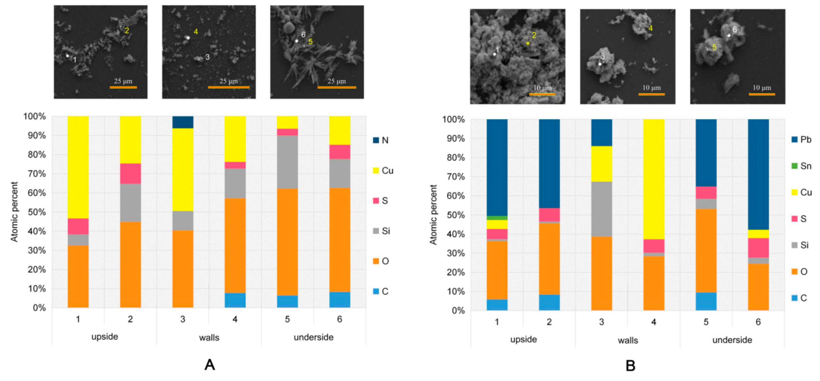
Microscopic inspection is employed to inspect the metallographic structure, micro-structure, composition and distribution of corrosion products by optical microscopy, scanning electron microscopy, an electron probe, Auger electron spectroscopy, X-ray photoelectron spectroscopy, X-ray diffractometry, etc. The fireside corrosion products collected from the water heaters were examined by XRD and SEM/EDS in this study.

4.2.1. SEM and EDS

The morphology, composition, and structure of corrosion products were characterized by a scanning electron microscope (SEM) and energy dispersive spectrometer (EDS). The corrosion products of the upsides and undersides of A and B were investigated in this study. The findings of these analyses are presented in Figure 9.
It was found by SEM/EDS that A is mainly composed of Cu, O and S elements, whereas B was mainly composed of Pb, Cu, O and S elements (Figure 9). One feature is of special interest, which is the enrichment of copper on B. The copper was exposed because the lead on the surface of the heat exchanger with a lead coating was completely corroded. The findings of macroscopic inspection (see Section 4.1.) were in good agreement with the results of the composition analyses, where the corrosion signal of the walls of the combustion chamber and upside and underside of the fins of A had the slight difference, as well as B.

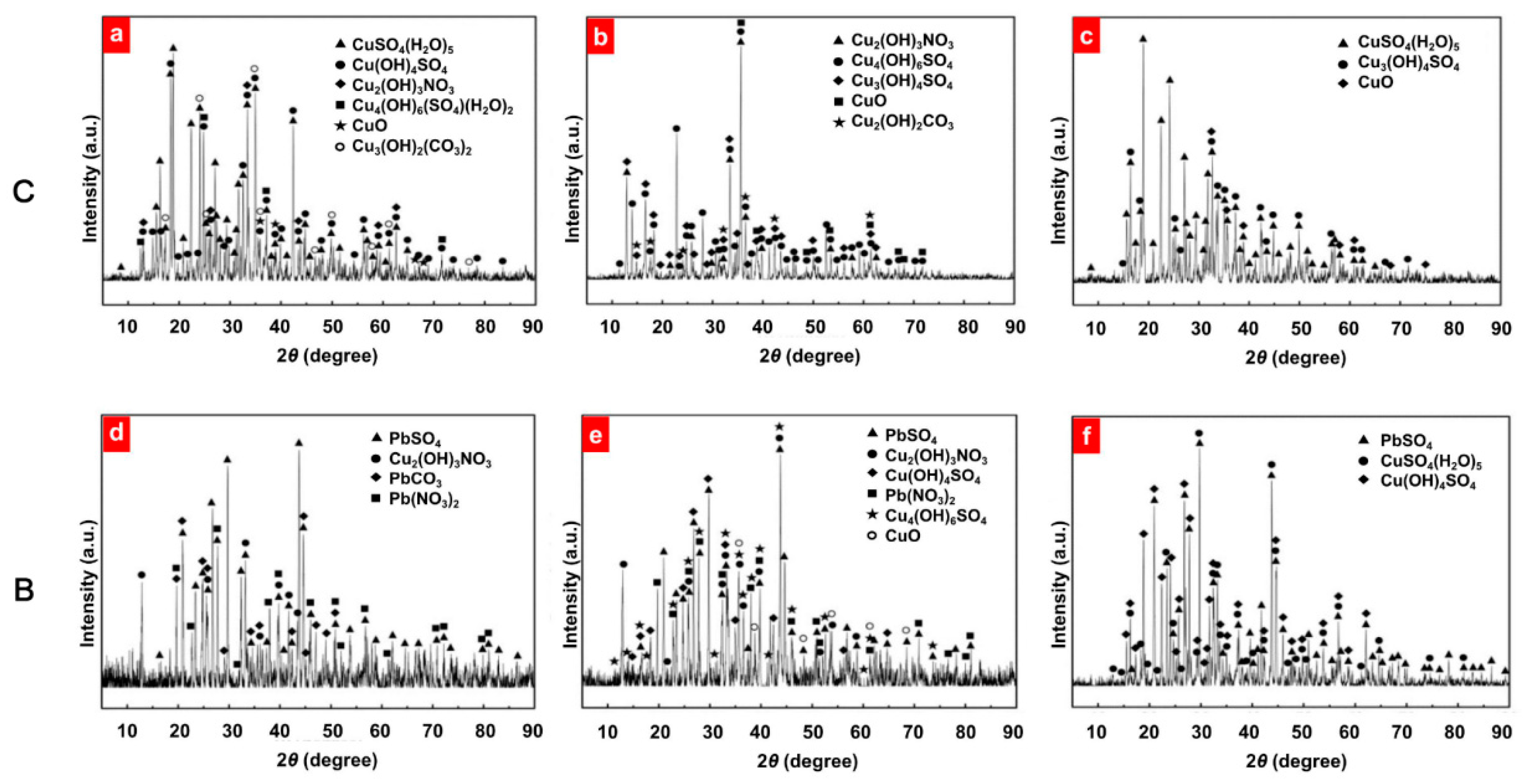
4.2.2. X-Ray Diffraction

Crystalline materials are mainly characterized by X-ray diffraction (XRD). XRD is a technique that uses direct data interpretation for rapid identification and quantification, where qualitative analysis is achieved to acquire the chemical composition of the corrosion product and the relative amounts of various phases are determined by a quantitative analysis of the intensity distribution of the diffraction line. Since the XRD examination results obtained for different heat exchangers with the same coating after 2000 cycles were similar, only the mappings of B and C are presented (Figure 10). It was concluded that the corrosion products of the four walls, upside and underside of the heat exchangers with a lead coating mainly consisted of Cu4(OH)6SO4, CuSO4(H2O)5 and Cu3(OH)4SO4, and Cu4(OH)6SO4 and Cu3(OH)4SO4, respectively. However, PbSO4 was the main corrosion product at the heat exchangers without a lead coating. Therefore, the corrosion products of the four walls, upside, and underside of the heat exchangers without a lead coating mainly consist of PbSO4 and Cu4(OH)6SO4, PbSO4 and PbSO4, and CuSO4(H2O)5, respectively. The results for the XRD presented confirm the findings of the SEM/EDS analyses.

4.3. Analysis of Corrosion Rates

The degree of corrosion of the heat exchanger was determined by the weight loss of the heat exchangers over the tests. Since the corrosion products were firmly attached to the heat exchangers, they were cleared by a high-pressure water jet. The corrosion rate can be calculated by the change in weight of the heat exchanger during the test cycle. As is shown in Table 10, the corrosion rate decreased with the increase of the heat input. Furthermore, the total mass lost was higher in the case of plating lead, but the reduction of copper was lower. A reasonable explanation for this can be given by the protection mechanism, which results in decreased corrosion on copper by the sacrifice of lead. However, the production of corrosion on lead can also fall off and block the heat exchanger. Although metal loss can be obtained directly by weighting, so that it is then convenient to calculate the corrosion rate, the results achieved are just the mean values. The limitation still remains that if the fluctuate of corrosion occurs during exposure cycles, the period, peak and corresponding rate of corrosion cannot be monitored in real time.

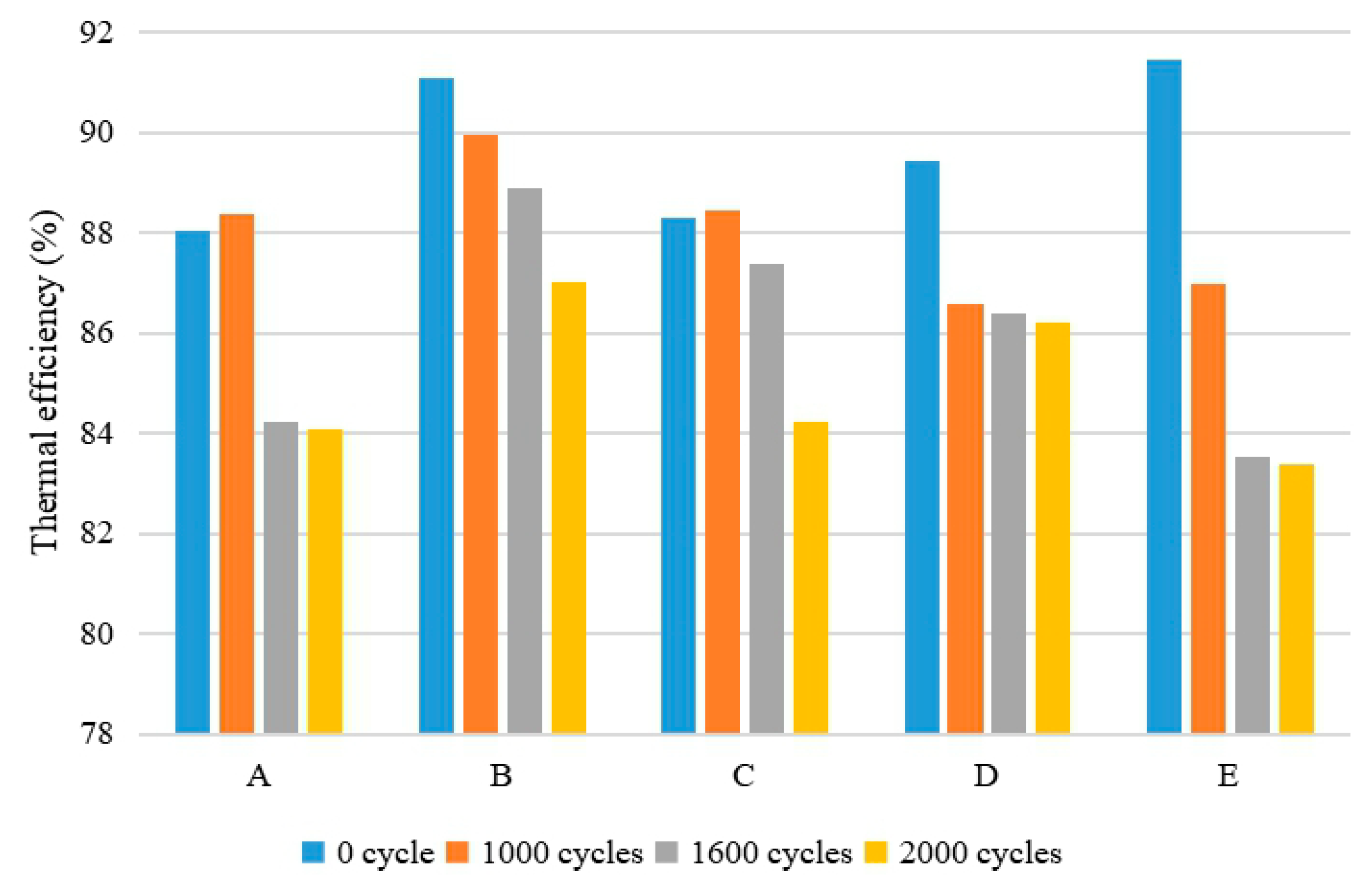
4.4. Analysis of Thermal Efficiency

The thermal efficiencies of the five heaters were tested at 0, 1000, 1600 and 2000 cycles at the rated heat input and at 1000, 1600 and 2000 cycles at the low heat input (about 14 kW).
The thermal efficiency at the low heat input was always a little higher than that at the high heat input, regardless of the type of heaters (see Figure 11 and Figure 12). With regard to the same heat input, the thermal efficiency of the heat exchangers with a lead coating was higher than that of those without a lead coating. Furthermore, as the operation progresses, the thermal efficiency of the heaters declines to varying degrees, since the accumulation of corrosion products on the flue gas side of the heat exchanger will weaken the heat transfer performance. The thermal efficiency of the heat exchangers with a lead coating was slightly lower than that of those without a lead coating in the initial state. An explanation for this can be given by the measurement error. After 2000 cycles, only B and D met the standard for the secondary grade of energy efficiency, while E is prohibited in the market according to GB 5932-2015.

4.5. Experimental Uncertainties

Due to the error of indirect measurement, the result was just an approximation or estimate of the value of the measurand and was thus only complete when accompanied by a statement of the uncertainty of that estimate. In the thermal efficiency tests of heaters, experimental uncertainties mainly came from various measurands measured indirectly, including the finite instrument resolution or discrimination threshold and variations in repeated observations. GUM (Guide to the Expression of Uncertainty in Measurement) [46] provides a standardized way to evaluate uncertainty in measurement [47] and the approach would be adopted to analyze the experimental uncertainty of thermal efficiency in this paper. By using the propagation law of uncertainty, all the components of uncertainty are combined to get a combining uncertainty (uc) and expanded uncertainty (U), which can contribute to obtaining relatively more accurate results.
uc = [∑Ni = 1[ci2u2(xi)]]1/2.
ci = ∂ηt/∂xi.
U = kuc.
Through estimating the propagating uncertainties of the original data, the final results of the thermal efficiency (Table 11 and Table 12) could be closer to the actual values. The calculation results produced using the GUM method as shown in Figure 13 and Figure 14. The thermal efficiency adding the uncertainty still maintained the tendency in Figure 11 and Figure 12. The experimental uncertainties at low heat input were around twice larger than these at high heat input. However, under the same heat input, the uncertainties were fairly close for different heaters.

4.6. Suggestions for Mitigating the Fireside Corrosion for Gas-Fired Instantaneous Water Heaters

The measures for anticorrosion of gas-fired instantaneous water heaters were proposed based on the results and analyses above, as follows:
  • Improve the quality of the gas. Gas meeting the first-class standard of civil fuel used in the gas-fired instantaneous water heater had positive effects on the reduction of the sulfide and sulfuric acid on the fireside of the heat exchanger;
  • Increase the volume of excess air. According to a flue gas analyzer test, the volume fraction of oxygen in the flue gas refers to 12.5% and the excess air coefficient in the flue gas to 2.47 transferred by the volume fraction of oxygen. According to the equations in Table 4 and the composition of the natural gas (see Table 8), the water dew point was 41.51 °C and the acid dew point was 125.5 °C. However, the temperature on the surface of heat exchanger near the combustion chambers was about 35 °C, which was lower than the dew points. Even the temperature away from the combustion chambers was 70 °C, which was relatively higher than the water dew point required to make the flue gas weak corrosive. The formula in Table 4 illustrated that the dew point decreased with the increase of the excess air coefficient. Based on this, by increasing the excess air coefficient, the dew point could be reduced below the surface temperature of the heat exchanger to decrease corrosion. However, the increase of the excess air coefficient also had a negative impact on the heat loss of flue gas and thermal efficiency. Therefore, the excess air coefficient should be proper considering both the thermal efficiency and the longevity of the heat exchanger;
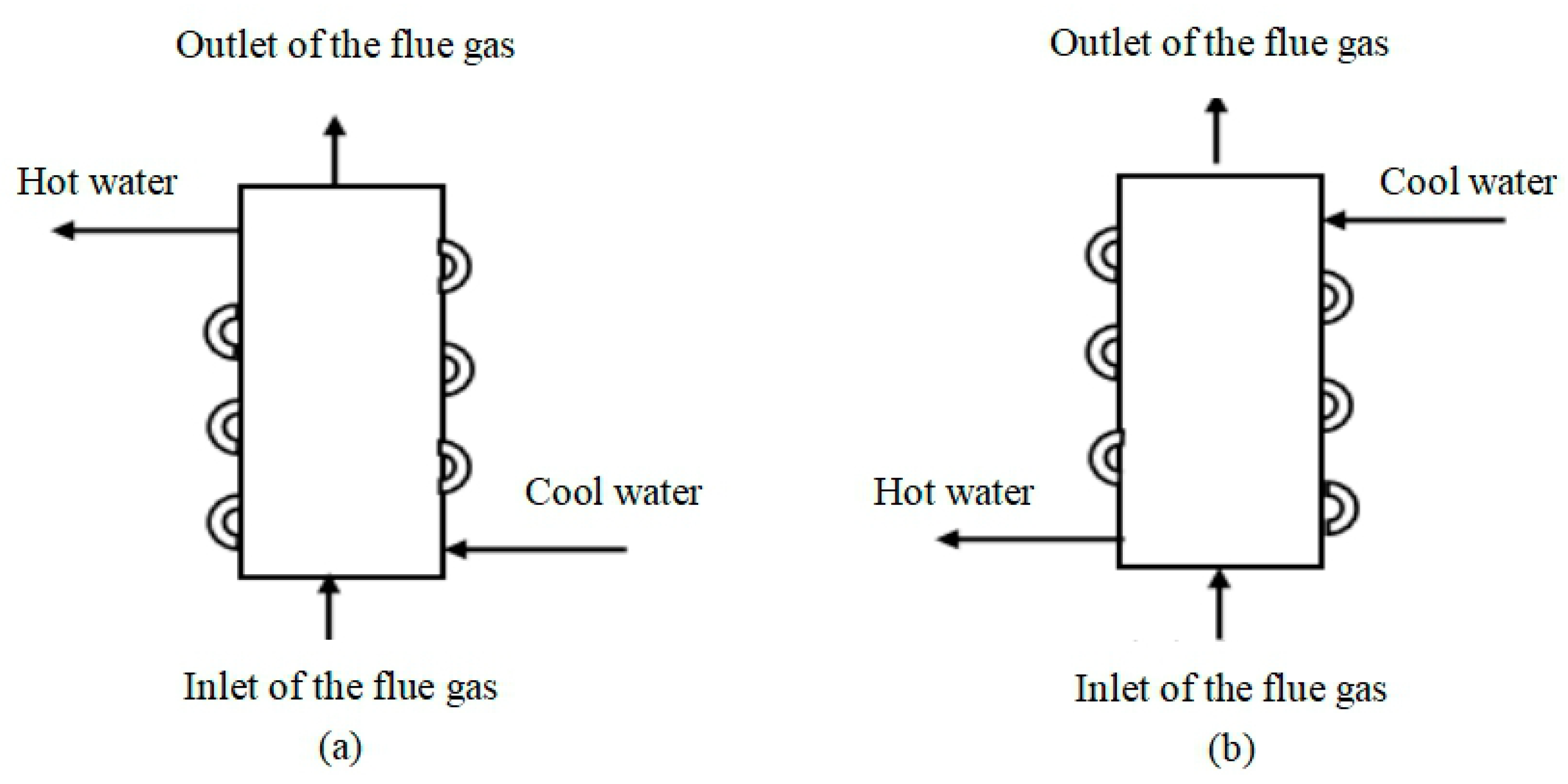
  • Change the inlet and outlet position of the heat exchanger. The tube arrangement of heat exchangers in the tests is shown in Figure 15a. After the combustion of the gas in the combustion chamber, the high-temperature flue gas flowed upward from the bottom of the heat exchanger. If the inlet pipe was located at the place of the fins of the heat exchanger, and the outdoor wall of combustion was wrapped around the outlet pipe of the hot water, as is shown in Figure 15b, the average temperature difference between the water and the flue gas would be decreased. As a result, a lower amount of condensed water and acid would be generated on the inner wall of the combustion chamber, and the corrosion would be weakened;
  • Choose a corrosion-resistant coating. To prevent an electrochemical reaction between the copper and acid solution, a coating could be plated on the surface of the heat exchanger, including a metal coating (protecting at the cost of sacrifice or forming a dense passivation layer, e.g., a nickel coating [48]) and non-metal coating (isolating the metal from acid solution, e.g., a fluoropolymer composite coating [49]). Furthermore, high-temperature resistance was also an important indicator of the coating and thus Fusible Ni-SA-c [50] could address this requirement to prolong the service life of the heat exchanger.
The experiments obtained the result that the content of copper in the corrosion products was greatly reduced in heat exchangers with a lead coating. Therefore, it could be concluded that the method of immersing an anti-corrosion material on the heat exchanger had a positive impact on the reduction of corrosion of its flue gas side. However, lead was not a good choice of coating because the lead sulfate would enter the air with the flue gas and pollute the environment. Therefore, more environmentally friendly materials should be chosen.

5. Conclusions

In this paper, corrosion and thermal efficiency tests were carried out for different types of heat exchangers, which were prone to produce electrochemical corrosion and thermal corrosion due to high-temperature flue gas during operation. We concluded four points in the paper, as follows:
  • It was found from macroscopic inspection that after 2000 cycles, the gap of fins of outlets of the flue gas was blocked by a flaky gray deposit whose amount increased with the increase of the heat input. The green solid particles on the walls of the heat exchanger were much more numerous than those for 1000 h, and the light green attachments covered a wider range. The fins of heat exchangers with a lead coating were corroded and even the copper surface was exposed;
  • The microscopic examination showed that the corrosion products of heat exchangers plated without lead were made up of Cu4(OH)6SO4, CuSO4(H2O)5 and Cu3(OH)4SO4, while those of heat exchangers plated with lead were made up of PbSO4, Cu4(OH)6SO4 and CuSO4(H2O)5;
  • The corrosion rate was calculated by changes of weight of the heat exchangers during the tests. The corrosion rate decreased with the increase of the heat input. Furthermore, the total mass lost was higher in the case of plating lead, but the reduction of copper was lower;
  • The thermal efficiency of heaters declined to different degrees, because the accumulation of flue gas side corrosion products has bad effects on the heat transfer performance of heat exchangers. The thermal efficiency at the low heat input was always a little higher than that at the high heat input, regardless of the type of heaters. With regard to the same heat input, the thermal efficiency of the heat exchangers with a lead coating was higher than that of those without a lead coating. Even with the experimental uncertainties, the thermal efficiency of the heaters maintained the trend above.
In this paper, due to the randomness of sampling, the quantitative analysis of corrosion products had some limitations in the process of collecting deposits. It still requires further investigation to validate a new observation through extracting multiple sampling points combined with mathematical statistics.
Furthermore, a lead coating was applied on the surface of copper heat exchanger to prevent corrosion. However, lead is not an environmentally friendly material, and under the tendency of energy conservation and environmental protection, additional studies are needed to find more efficient and eco-friendly coatings instead of lead coating.

Author Contributions

Conceptualization, X.H.; writing—original draft, X.H. and M.S.; writing—review and editing, Y.K.

Funding

This research was funded by the National Key Project of Research and Development Program of the 13th Five-Year, grant number 2018YFD1100704.

Conflicts of Interest

The authors declare no conflicts of interest.

Nomenclature

ATuned coefficient
BTuned coefficient
CTuned coefficient
DTuned coefficient
F1Empirical elemental concentration of carbon correction factors
F2Empirical excess air correction factors
αExcess air fraction
ξElemental concentration of carbon
SSulfur volume fraction for gas
TAcid dew point temperature for combustion flue gases, °C
ηtThermal efficiency, %
MMass per minutes, kg/min
CpHeat capacity at constant pressure
tw2The temperature of the hot water, °C
tw1Influent temperature, °C
VConsumption of water heater gas, m3/min
Q1Lower heating value of gas, MJ/m3
tTemperature, °C
PPressure, kPa
PsPartial vapor pressure, Pa
ucCombined uncertainty, %
xiInput quantity
u(xi)Standard uncertainty of an input quantity, %
ciSensitivity coefficient
UExpanded uncertainty, %
kCoverage factor, k = 2
Subscripts
nAtom number of carbon per cubic meter
mAtom number of hydrogen per cubic meter
gGas
ambAtmospheric

References

  1. World Green Building Council. 2018 Global Status Report: Towards a Zero-Emission, Efficient and Resilient Buildings and Construction Sector; World Green Building Council: London, UK, 2018. [Google Scholar]
  2. Building Energy Research Center of Tsinghua University. China Building Energy Consumption Report (2017); Building Energy Research Center of Tsinghua University: Beijing, China, 2017. [Google Scholar]
  3. BP. Statistical Review of World Energy; British Petroleum: London, UK, 2018. [Google Scholar]
  4. BP. Energy Outlook, 2018 ed.; British Petroleum: London, UK, 2018. [Google Scholar]
  5. IEC 60335:2010+A1:2013 Household and Similar Electrical Appliances—Safety—Part 1: General Requirements, 5.1 ed.; DOE, IEA Publications: Washington, DC, USA, 2014.
  6. Domestic Gas Instantaneous Water Heater (GB6932–2015); Administration of Quality Supervision, Inspection and Quarantine (AQSIQ) Publications: Beijing, China, 2017.
  7. Minimum Allowable Values of Energy Efficiency and Energy Efficiency Grades for Domestic GAS INSTAntaneous Water Heaters and Gas Fired Heating and Hot Water Combi—Boilers (GB 20665–2015); Administration of Quality Supervision, Inspection and Quarantine (AQSIQ) Publications: Beijing, China, 2016.
  8. EN 26:1997/A3:2006:E Gas-Fired Instantaneous Water Heaters for the Production of Domestic Hot Water, Fitted With Atmospheric Burners; CEN/TC 48 Publications: Brussels, Belgium, 2006.
  9. Steinhagen, R.; Müller-Steinhagen, H.; Maani, K. Problems and costs due to heat exchanger fouling in New Zealand industries. Heat Transf. Eng. 1993, 14, 19–30. [Google Scholar] [CrossRef]
  10. Li, X.G.; Zhang, D.W.; Liu, Z.Y.; Li, Z.; Du, C.W.; Dong, C.F. Materials science: Share corrosion data. Nature 2015, 527, 441–442. [Google Scholar] [CrossRef] [PubMed]
  11. Corrosion Cost and Preventive Strategies in the United States; Federal Highway Administration Publications: Washington, DC, USA, 2002.
  12. Survey of Corrosion Cost in Japan; Committee on Cost of Corrosion in Japan Publications: Tokyo, Japan, 2001.
  13. Hou, B.R.; Lu, D.Z. Corrosion Cost and Preventive Strategies in China. Bull. Chin. Acad. Sci. 2018, 33, 601–609. (In Chinese) [Google Scholar]
  14. Srikanth, S.; Ravikumar, B.; Das, S.K.; Gopalakrishna, K.; Nandakumar, K.; Vijayan, P. Analysis of failures in boiler tubes due to fireside corrosion in a waste heat recovery boiler. Eng. Fail. Anal. 2003, 10, 59–66. [Google Scholar] [CrossRef]
  15. Malik, A.U.; Al-Muaili, F.; Al-Ayashi, M.; Meroufel, A. An investigation on the corrosion of flue gas sensor in boiler stack. Case Stud. Eng. Fail. Anal. 2003, 1, 200–207. [Google Scholar] [CrossRef]
  16. Li, M.J.; Tang, S.Z.; Wang, F.L.; Zhao, Q.X.; Tao, W.Q. Gas-side fouling, erosion and corrosion of heat exchangers for middle/low temperature waste heat utilization: A review on simulation and experiment. Appl. Therm. Eng. 2017, 126, 737–761. [Google Scholar] [CrossRef]
  17. Lampert, D. Low-temperature corrosion in feed-heaters heated by flue-gas. Brown Boveri Rev. 1978, 65, 691–695. [Google Scholar]
  18. Okoro, S.C.; Montgomery, M.; Frandsen, F.J.; Pantleon, K. Effect of water vapor on high-temperature corrosion under conditions mimicking biomass firing. Energy Fuels 2015, 29, 5802–5815. [Google Scholar] [CrossRef]
  19. Shoemaker, L.; Crum, J.; Maitra, D. Recent Experience with Stainless Steels in Wet Limestone FGD Air Pollution Control Service; NACE International Publications: Houston, TX, USA, 2011. [Google Scholar]
  20. Pan, P.Y.; Chen, H.; Liang, Z.Y.; Zhao, Q.X. Desulfurized flue gas corrosion coupled with deposits in a heating boiler. Corrosion Sci. 2018, 131, 126–136. [Google Scholar] [CrossRef]
  21. Khodamorad, S.H.; Alinezhad, N.; Fatmehsari, D.H.; Ghahtan, K. Stress corrosion cracking in Type.316 plates of a heat exchanger. Case Stud. Eng. Fail. Anal. 2016, 5, 59–66. [Google Scholar] [CrossRef]
  22. Angell, P.; Urbanic, K. Sulphate-reducing bacterial activity as a parameter to predict localized corrosion of stainless alloys. Corros. Sci. 2000, 42, 897–912. [Google Scholar] [CrossRef]
  23. Stein-Brzozowska, G.; Maier, J.; Scheffknecht, G.; Cumbo, D.; Masci, S.; Tosi, E.; Corraggio, G.; Faleni, M.; Biasci, L. Fireside corrosion of applied and modern superheater-alloys under oxy-fuel conditions. Energy Procedia 2013, 37, 1448–1461. [Google Scholar] [CrossRef]
  24. Wang, X.; Fang, M.; Zhang, L.; Ding, H.; Liu, Y.; Huang, Z.; Huang, S.; Yang, J. Solid particle erosion of alumina ceramics at elevated temperature. Mater. Chem. Phys. 2013, 139, 765–769. [Google Scholar] [CrossRef]
  25. Shida, Y.; Fujikawa, H. Particle erosion behaviour of boiler tube materials at elevated temperature. Wear 1985, 103, 281–296. [Google Scholar] [CrossRef]
  26. Kladkaew, N.; Idem, R.; Tontiwachwuthikul, P.; Saiwan, C. Studies on corrosion and corrosion inhibitors for amine based solvents for CO2 absorption from power plant flue gases containing CO2, O2 and SO2. Energy Procedia 2011, 4, 1761–1768. [Google Scholar] [CrossRef]
  27. Paz, M.D.; Zhao, D.; Karlsson, S.; Liske, J.; Jonsson, T. Investigating corrosion memory: The influence of previous boiler operation on current corrosion rate. Fuel Process. Technol. 2017, 156, 348–356. [Google Scholar] [CrossRef]
  28. Su, J.X.; Ma, M.Y.; Wang, T.J.; Guo, X.M.; Hou, L.G.; Wang, Z.P. Fouling corrosion in aluminum heat exchangers. Chin. J. Aeronaut. 2015, 28, 954–960. [Google Scholar] [CrossRef] [Green Version]
  29. Kleiner, M.B.; Kühn, S.A.; Haberger, K. High Performance Forced Air Cooling Scheme Employing Microchannel Heat Exchangers. IEEE Trans. Compon. Pack. Manuf. 1995, 18, 795–804. [Google Scholar] [CrossRef]
  30. Gurrappa, I. Cathodic protection of cooling water systems and selection of appropriate materials. J. Mater. Process. Tech. 2005, 166, 256–267. [Google Scholar] [CrossRef]
  31. Tian, J.; Kim, T.; Lu, T.J.; Hodson, H.P.; Queheillalt, D.T.; Sypeck, D.J.; Wadley, H.N.G. The effects of topology upon fluid-flow and heat-transfer within cellular copper structures. Int. J. Heat Mass Transf. 2004, 47, 3171–3186. [Google Scholar] [CrossRef]
  32. Ranjbar, K. Effect of flow induced corrosion and erosion on failure of a tubular heat exchanger. Mater. Des. 2010, 31, 613–619. [Google Scholar] [CrossRef]
  33. Damon, G.H. Acid corrosion of steel: Effect of carbon content on the corrodibility of steel in sulfuric acid. Ind. Eng. Chem. 1941, 33, 67–69. [Google Scholar] [CrossRef]
  34. Wang, Y.G.; Zhao, Q.X.; Zhang, Z.X.; Zhang, Z.C.; Tao, W.Q. Mechanism research on coupling effect between dew point corrosion and ash deposition. Appl. Therm. Eng. 2013, 54, 102–110. [Google Scholar] [CrossRef]
  35. Zucchi, F.; Trabanelli, G.; Monticelli, C. The inhibition of copper corrosion in 0.1M NaCl under heat exchange conditions. Corros. Sci. 1996, 38, 147–154. [Google Scholar] [CrossRef]
  36. Brady, M.P.; Banta, K.; Mizia, J.; Lorenz, N.; Leonard, D.N.; Yamamoto, Y.; Defoort, M.; Keiser, J.R. Alloy corrosion considerations in low-cost, clean biomass cookstoves for the developing world. Energy Sustain. Dev. 2017, 37, 20–32. [Google Scholar] [CrossRef]
  37. Hwanga, K.; Song, C.H.; Saito, K.; Kawai, S. Experimental study on titanium heat exchanger used in a gas fired water heater for latent heat recovery. Appl. Therm. Eng. 2010, 30, 2730–2737. [Google Scholar] [CrossRef]
  38. Gruber, T.; Schulze, K.; Scharler, R.; Obernberger, I. Investigation of the corrosion behaviour of 13CrMo4-5 for biomass fired boilers with coupled online corrosion and deposit probe measurements. Fuel 2015, 144, 15–24. [Google Scholar] [CrossRef]
  39. Jeong, K.; Levy, E.K. Theoretical prediction of sulfuric acid condensation rates in boiler flue gas. Int. J. Heat Mass Trans. 2012, 55, 8010–8019. [Google Scholar] [CrossRef]
  40. Blanco, J.M.; Peña, F. Increase in the boiler’s performance in terms of the acid dew point temperature: Environmental advantages of replacing fuels. Appl. Therm. Eng. 2008, 28, 777–784. [Google Scholar] [CrossRef]
  41. Guo, J.Z.; Liu, X.W.; Wang, H.; Zhang, P.H.; Xu, Y.S.; Chen, Z.G.; Xu, M.H. Effect of HCl and CO on sulfur trioxide formation mechanisms during oxy fuel combustion. Fuel Process. Technol. 2018, 174, 95–103. [Google Scholar] [CrossRef]
  42. Zheng, Y.X.; Zhao, H.Y.; Ye, Y.Z.; Zhong, J.S.; Xia, Z.Z.; Wu, G.F. Experimental study on corrosion prevention of low-temperature section of heat exchanger in condensing gas water heater. Gas. Heat 2007, 27, 35–41. (In Chinese) [Google Scholar]
  43. Jia, M.S.; Ling, C.M. Factors of affecting the flue gas acid dew point temperature and its way of calculation. Ind. Boiler 2013, 6, 31–35. (In Chinese) [Google Scholar]
  44. Haar, L.; Gallagher, J.S.; Kell, G.S. NBS/NRC Steam Tables: Thermodynamic and Transport Properties and Computer Programs for Vapor and Liquid States of Water; Hemisphere Publishing Company: Washington, DC, USA, 1984. [Google Scholar]
  45. Bahadori, A. Estimation of combustion flue gas acid dew point during heat recovery and efficiency gain. Appl. Therm. Eng. 2011, 31, 1457–1462. [Google Scholar] [CrossRef]
  46. International Organization for Standardization. A Guide to Expression of Uncertainty in Measurement (ISO /1995); International Organization for Standardization: Geneva, Switzerland, 1995. [Google Scholar]
  47. Bürger, S.; Essex, R.M.; Mathew, K.J.; Richter, S.; Thomas, R.B. Implementation of Guide to the expression of Uncertainty in Measurement (GUM) to multi-collector TIMS uranium isotope ratio metrology. Int. J. Mass Spectrom. 2010, 294, 65–76. [Google Scholar] [CrossRef]
  48. He, Y.L.; Walsh, D.; Shi, C. Fluoropolymer composite coating for condensing heat exchangers: Characterization of the mechanical, tribological and thermal properties. Appl. Therm. Eng. 2015, 91, 387–398. [Google Scholar] [CrossRef]
  49. Wang, Y.C.; Tang, G.H. Prediction of sulfuric acid dew point temperature on heat transfer fin surface. Appl. Therm. Eng. 2016, 98, 492–501. [Google Scholar] [CrossRef]
  50. Chen, J.; Ninomiya, Y.; Naganuma, H.; Sasaki, Y.; Noguchi, M.; Cho, H.; Ueki, Y.; Yoshiie, R.; Naruse, I. Development of thermal spraying materials through several corrosion tests for heat exchanger tube of incinerators. Fuel Process. Technol. 2016, 141, 216–224. [Google Scholar] [CrossRef]
Figure 1. Schematic view of a gas-fired instantaneous water heater.
Energies 12 02583 g001
Figure 2. Photo of five gas-fired instantaneous water heaters. From left to right: (A)–(E).
Energies 12 02583 g002
Figure 3. Diagram of the test system of the water heater. 1—flue gas analyzer; 2—water pressurizer; 3—inlet thermometer; 4—gas analyzer; 5—pressure regulator; 6—gas flowmeter; 7—U type pressure gauge; 8—outlet thermometer.
Energies 12 02583 g003
Figure 4. Structural map of the heat exchanger and its section view.
Energies 12 02583 g004
Figure 5. Photos of four walls of combustion chambers (exposure time 0 cycles, 1000 cycles and 2000 cycles. (A)–(E) represent different test samples of gas-fired instantaneous water heaters, as in Table 6).
Energies 12 02583 g005
Figure 6. Photos of the underside of the fins of the heat exchangers.
Energies 12 02583 g006
Figure 7. Photos of the upside of the fins of the heat exchangers.
Energies 12 02583 g007
Figure 8. Photos of the burners.
Energies 12 02583 g008
Figure 9. Scanning electron microscope/energy dispersive spectrometer (SEM/EDS) element mappings and analysis results of the deposits during the corrosion measurements of (A) (left) and (B) (right).
Energies 12 02583 g009
Figure 10. X-ray diffraction (XRD) examination results of the deposits for (B) (down) and (C) (up). (ac), are the qualitative analyses for the upside, walls and underside of (C), respectively; (df) are the qualitative analyses for the upside, walls and underside of (B), respectively.
Energies 12 02583 g010
Figure 11. Thermal efficiency of five water heaters operated under the rated heat input.
Energies 12 02583 g011
Figure 12. Thermal efficiency of five water heaters operated under low heat input (about 14 kW).
Energies 12 02583 g012
Figure 13. Experimental uncertainties of the thermal efficiency of the heaters operated under high heat input.
Energies 12 02583 g013
Figure 14. Experimental uncertainties of the thermal efficiency of the heaters operated under high heat input.
Energies 12 02583 g014
Figure 15. Inlet and outlet position of the heat exchanger. (a) Current structure of the heat exchanger in the experiment. (b) Structure after reform.
Energies 12 02583 g015
Table 1. Energy efficiency rate of the water heater.
Energy Efficiency RateMinimum Thermal Efficiency (%)
Rating Heat Input≤50% Rating Heat Input
19694
28884
384-
Table 2. Corrosion costs in some countries.
CountryYearAnnual Corrosion CostThe Proportion of Corrosion Cost in GDP/GNP
China2014More than 2.1 trillion yuan3.34% [13]
U.S.1998$276 billion (direct)3.1% (directly)
Around 6% (direct and indirect) [11]
Japan19973938 billion yen0.77% [12]
India2004$364 billion (direct)3.1% (direct and indirect) 1
Britain19711.365 billion pounds3.5% [13]
1 Said by Houston-based NACE International (National Association of Corrosion Engineers) president George Hays during his presentation at the NACE International India Section conclave in Mumbai.
Table 3. Correspondence principle between partial vapor pressure and water dew point (Data from [44]).
Partial Vapor Pressure (kPa)Water Dew Point (°C)
5.534.589
636.167
6.537.635
739.008
7.540.299
841.518
8.542.673
943.771
9.544.817
1045.817
Table 4. Computational formula of the flue gas acid dew point (Adapted from [45]).
Number of LineFormulaCoefficient Formula
1ln(F1) = a + b/S + c/S2 + d/S3 a = A1 + B1/ξ + C1/ξ2 + D1/ξ3
b = A2 + B2/ξ + C2/ξ2 + D2/ξ3
c = A3 + B3/ξ + C3/ξ2 + D3/ξ3
d = A4 + B4/ξ + C4/ξ2 + D4/ξ3
2ln(F2) = a + b/(F1) + c/(F1)2 + d/(F1)3 a = A1 + B1/α + C1/α2 + D1/α3
b = A2 + B2/α + C2/α2 + D2/α3
c = A3 + B3/α + C3/α2 + D3/α3
d = A4 + B4/α + C4/α2 + D4/α3
3ln(T) = a + b(F2) + c(F2)2 + d(F2)3 a = A1 + B1/ξ + C1/ξ2 + D1/ξ3
b = A2 + B2/ξ + C2/ξ2 + D2/ξ3
c = A3 + B3/ξ + C3/ξ2 + D3/ξ3
d = A4 + B4/ξ + C4/ξ2 + D4/ξ3
Table 5. Tuned coefficients for equations (Adapted with permission from [45], Copyright Elsivier, 2011).
CoefficientTuned Coefficient Values for Equations in Line 1 of Table 4Tuned Coefficient Values for Equations in Line 2 of Table 4Tuned Coefficient Values for Equations in Line 3 of Table 4
A11.616945239105.9522580890
B16.1776693132 × 10−11.21681939013.7435527319 × 10−2
C1−3.9653315194 × 10⁻¹−1.2791492533 × 10⁻¹−2.9745433707 × 10⁻²
D18.9951003043 × 10−23.7468691518 × 10−38.0120588749 × 10−3
A2−7.3040211893 × 10−301.4895974061 × 10⁻²
B26.9240838238 × 10−3−3.5038003546−2.5447171264 × 10⁻²
C2−5.8556137034 × 10−33.5352583979 × 10−12.8643928069 × 10⁻²
D21.5959152735 × 10−3−1.0220477526 × 10⁻²−8.5637681681 × 10⁻³
A31.0870177961 × 10−506.4518970719 × 10⁻⁵
B3−8.5890701138 × 10−64.24570672129.7931326979 × 10−3
C38.1950413835 × 10−6−4.2048282453 × 10⁻¹−1.1108881728 × 10⁻²
D3−2.4343154548 × 10−61.2049410160 × 10−23.3304384324 × 10⁻³
A4−6.1128433684 × 10−905.0957445440 × 10⁻⁵
B44.6119957003 × 10−9−1.9582714148−9.3033575126 × 10⁻⁴
C44.4972769065 × 10−91.8294597537 × 10−11.0575132247 × 10−3
D41.3588028938 × 10−9−5.1643724550 × 10⁻³−3.1726950227 × 10⁻⁴
Table 6. Test samples of gas-fired instantaneous water heaters.
Test PrototypeThermal Load (kW)Coating on the Heat Exchanger
A28None
B28Lead
C32None
D32Lead
E40None
Table 7. Detailed specifications of heat exchangers’ components.
ComponentsMaterialsSpecifications (mm)
Water inletCopper (C1220T)Φ12 × 0.6
(diameter × thickness)
Water outletCopper (C1220T)Φ12 × 0.6
Connecting pipeCopper (C1220T)Φ12 × 0.7
TubeCopper (C1220T)Φ16 × 0.8
Tube pitch-32
Coil out of the shellCopper (C1220T)Φ12 × 0.6
ShellCopper (C1220P-1/4H)0.4 (thickness)
FinsCopper (C1220P-1/4H)0.25 (thickness)
Fin pitch-2.55
Fin height-68
Coating of B and DMore than 95% lead0.2–0.3 (thickness)
Table 8. Basic properties of the gas at Chongqing Hantu gas distribution station.
Test ContentUnitsResults
CH4%95.02
C2H61.719
C3H80.287
i-C4H100.0526
n-C4H100.0526
i-C5H120.0193
n-C5H120.0116
C6+0.0152
O20.28
N21.34
CO21.2
Higher heating value (20 °C)MJ/m339.46
Lower heating value (20 °C)MJ/m335.46
H2Smg/m312.29
Table 9. Test instruments.
NameModel
1Flue gas analyzerecom-J2KN
2Gas chromatographGC-1690
3Gas flowmeterDC-2 (10L/R)
4Gas thermometerMercury thermometer (0–100 °C)
5Gas pressure gaugeU pressure gauge (0–12 kPa)
6Inlet and outlet thermometerMercury thermometer (0–100 °C)
7Flue gas thermometerMercury thermometer (0–200 °C)
8ScaleKW-30B (0–30 kg)
Table 10. Calculation of the corrosion rate.
Test PrototypeABCDE
Weight before tests (g)36983960371239463675
Weight after tests (g)35803740359538253595
Loss (g)11822011712180
Rate of corrosion (g/h)0.05900.1100.05850.06050.0400
Standard uncertainty (g/h) [46]0.001820.001930.001830.001940.00182
Table 11. Experimental uncertainty of the thermal efficiency of the heaters operated under high heat input.
CyclesTest Prototypeuc (%)U (%)Final Results of the Thermal Efficiency (%)
1000A0.260.5386.40 ± 0.53
B0.280.5588.47 ± 0.55
C0.310.6288.90 ± 0.62
D0.260.5288.39 ± 0.52
E0.310.6187.00 ± 0.61
1600A0.260.5184.22 ± 0.51
B0.290.5889.97 ± 0.58
C0.300.6187.38 ± 0.61
D0.250.5086.59 ± 0.50
E0.260.5183.53 ± 0.51
2000A0.330.6684.07 ± 0.66
B0.280.5687.01 ± 0.56
C0.290.5883.22 ± 0.58
D0.260.5186.22 ± 0.51
E0.250.5083.40 ± 0.50
Table 12. Experimental uncertainty of the thermal efficiency of the heaters operated under low heat input.
CyclesTest Prototypeuc (%)U (%)Final Results of the Thermal Efficiency (%)
1000A0.561.1194.07 ± 1.11
B0.450.9195.56 ± 0.91
C0.531.0690.69 ± 1.06
D0.531.0694.69 ± 1.06
E0.651.3092.06 ± 1.30
1600A0.511.0291.93 ± 1.02
B0.430.8690.90 ± 0.86
C0.531.0788.42 ± 1.07
D0.490.9893.47 ± 0.98
E0.561.1288.25 ± 1.12
2000A0.631.2790.98 ± 1.27
B0.470.9389.59 ± 0.93
C0.521.0487.22 ± 1.04
D0.500.9992.27 ± 0.99
E0.581.1791.64 ± 1.17

