Article

Experimental Studies of Fuel Injection in a Diesel Engine with an Inclined Injector

by
V. G. Kamaltdinov
1,*,
V. A. Markov
2,
I. O. Lysov
1,
A. A. Zherdev
2 and
V. V. Furman
3
1
Motor Transport Faculty, South Ural State University, 76, Lenin Ave., Chelyabinsk 454080, Russia
2
Power Engineering Faculty, Bauman Moscow State Technical University, 5, 2-ya Baumanskaya Str., Moscow 105005, Russia
3
Design and Production Enterprise “Dieselautomatika”, 109, Chernyshevskogo Str., Saratov 410017, Russia
*
Author to whom correspondence should be addressed.
Energies 2019, 12(14), 2643; https://doi.org/10.3390/en12142643
Submission received: 3 June 2019 / Revised: 2 July 2019 / Accepted: 6 July 2019 / Published: 10 July 2019
(This article belongs to the Special Issue Experimental and Numerical Analysis of Fuel Spray in Engines)

Abstract

:
Comparative experimental studies of fuel sprays evolution dynamics in a constant volume chamber were carried out with a view to reduce the uneven distribution of diesel fuel in the combustion chamber when the Common Rail injector is inclined. The fuel sprays was captured by a high-speed camera with simultaneous recording of control pulses of camera and injector on an oscilloscope. Two eight-hole diesel injectors were investigated: One injector with identical orifice diameter (nozzle 1) and another injector with four orifices of the same diameter as orifices of nozzle 1 and four orifices of enlarged diameters (nozzle 2). Both injectors were tested at rail pressure from 100 to 165 MPa and injector control pulse width of 1.5 ms. The dynamics of changes in the spray penetration length and spray cone angle were determined. It was found that sprays develop differently in nozzle 1 fuel. The difference in the length of fuel sprays is 10–15 mm. As for nozzle 2, the fuel sprays develop more evenly: The difference in length is no more than 3–5 mm. The difference of the measured fuel spray cone angles for nozzle 1 is 0.5°–1.5°, and for nozzle 2 is 3.0°–4.0°. It is concluded that the differential increase in the diameters of nozzle orifices, the axes of which are maximally deviated from the injector axis, makes it possible to reduce the uneven distribution of fuel in the combustion chamber and improve the combustion process and the diesel performance as a whole.

1. Introduction

In modern diesel engines, the centrally-mounted fuel injector is often arranged inclined from the axis of the piston bowl, bypassing the valve cover, which facilitates its removal and installation. During injection, the fuel sprays form a “tent” shape and are dispersed symmetrically relative to the cylinder axis (Figure 1). To do this, the nozzle orifices of injector are made at different angles from the injector axis. As a result, the fuel flows out from different orifices under different conditions. The alignment of the fuel–air mixture is provided by its swirl or displacement of the combustion chamber axis in piston. In high power diesel engines with a cylinder diameter larger than 150 mm, an open combustion chamber of the Hesselman type is often used. In this case, the mixture formation is performed without air swirl, and the fuel is distributed unevenly over the combustion chamber. On one side of the combustion chamber where the mixture is richer than that on the other (opposite), combustion runs at higher temperatures and more toxic substances (soot and nitrogen oxides) are formed.
In studies of the influence of the nozzle holes geometry on the injection, mixing, and combustion processes, two approaches are mainly used: experimental and numerical. Experiments are performed on test stands with visualization of the injection process in a constant volume chamber and high-speed video shooting [1,2,3,4,5,6]. Numerical modeling is performed using CFD (computational fluid dynamic) technologies [7,8,9,10].
The influence of the nozzle holes geometry on spray penetration, spray cone angle, and spray volume was experimentally investigated [11,12,13]. The effect of the cross-section shape of nozzle orifice including round, elliptical, and triangular on the cone angle and fuel spray length was studied at injection pressures from 50 to 160 MPa, the pressure in a constant volume chamber of 1.0–3.0 MPa, and nitrogen gas temperature of 300 K [14,15,16,17]. High-speed video filming was carried out in two planes.
The paper [18] reports an investigation on the transient evolution of diesel flame based upon Schlieren imaging. The study was conducted in a single-hole nozzle with orifice diameter of 82 and 138 μm, when the injection pressure was 50, 100, and 150 MPa, and the oxygen concentration was 0% (non-reacting) and 21% (reacting). In this work, the length and cone angle of the liquid and vapor phases (fuel sprays) were determined.
In constant volume chambers heated up to 600–800 K, the spray penetration length and spray cone angles in liquid and vapor phases were measured with the help of Schlieren visualization [19,20]. The test injection pressures are selected as: 40, 60, 80, 100, 120, 140, and 160 MPa. A single-hole nozzle (with orifice diameters of 0.26 and 0.3 mm) was installed in injector. The Schlieren visualization was also used to study an eight-hole diesel solenoid injector (with orifice diameters of 0.13, 0.194, and 0.229 mm) [21]. The test injection pressures selected were 500 to 2100 bar and temperature of 600–950 K.
The influence of the geometry of nozzle orifices on the mixture formation and combustion process was studied in a constant volume chamber and the combustion chamber of a multi-cylinder diesel engine [22,23,24].
The analysis of the influence of the nozzle orifices inclination angle on the hydraulic characteristics was carried out. For this, three different 10-hole nozzles with different included angles of 90°, 140°, and 155° and identical nozzle diameter of 0.09 mm were evaluated. Spray penetration length, instantaneous injection rate, and momentum flux at nozzle orifice outlet were measured in a wide range of injection pressures from 23 to 200 MPa [25,26].
The spray development of diesel fuel in a constant volume chamber with Common Rail fuel injection system, in which the injector has four nozzle orifices with different diameters from 90 to 150 microns, has been studied [12]. The fuel injector nozzle had four orifices aligned on a radial plane with diameters of 90, 110, 130, and 150 µm. Fuel was injected into a nitrogen environment with room temperature 298 K and densities of 17.5, 24.2, and 32.7 kg/m3 and during fuel rail-pressures of 1000, 1500, and 2000 bar. The axis of the nozzle orifices had a slight deviation from the injector axis (±10° and ±30°). The length and cone angle of sprays were measured, as well as the deviations of the axes of the sprays from the axes of the orifices. The displacement of the spray axis from the orifice axis was the smallest for the orifice with the largest diameter (0.150 mm); the maximum spray velocities were 150–250 m/s at 0.6–0.7 ms from the start of injection.
Interesting results were obtained when fuel was injected into a constant volume chamber by using a piezo electric injector: number of nozzle orifices—seven, spray included angle—158°, outlet diameter—0.152 mm [27]. At fuel pressures of 60 and 150 MPa, high temperatures of 870 and 950 K, and different densities in the chamber of 13.3, 19.0, and 24.6 kg/m3, different sprays had different lengths.
It was experimentally established that the geometry of the nozzle orifice with a large diameter (more than 300 μm) has a significant effect on the process of mixture formation and combustion [22]. Nozzle orifices with large inclination angles have a smaller mass flow rate in stationary conditions due to higher input losses.
The cylindrical nozzle orifice with larger diameter, in spite of higher mass flow rate, shows a slower development of the fuel plume when compared to the conical nozzle orifice [6].
An increase of nozzle orifice diameter can lead to the increase in the Sauter mean diameter of fuel droplet at the initial stage of injection process and the decrease in fuel evaporation [28]. As a result, it is possible to slow down the initial stage of combustion process and reduce the pressure and temperature of combustion in the cylinder of a diesel engine.
Analysis of the publications shows that a large number of different studies have been conducted on the effect of the diameter, shape, and length of nozzle orifice, its angular position relative to the diesel injector axis, and much more on the fuel spray characteristics. However, applying the results described above in high power diesel engines with a cylinder diameter larger than 150 mm and an axisymmetric Hesselman-type combustion chamber is problematic due to their design features.
The present work is concerned with experimental studies and visualization of the processes of fuel injection, air-fuel formation, and fuel spray evolution in a constant volume chamber with the aim of reducing the uneven distribution of diesel fuel in the combustion chamber for diesel engine with inclined injector.

2. Materials and Methods

Initially it was assumed that when a Common Rail fuel injection system with inclined injector is used, there may be differences in the fuel supply between the injection orifices. The object of the experimental studies was diesel fuel injectors with electromagnetic control (solenoid diesel injector) (Figure 1). They are designed to work with a Common Rail fuel injection system for industrial diesel engines with a cylinder diameter larger than 150 mm. Fuel injection begins when a current is applied to the solenoid valve of injector (Figure 2). The current transducer LTS 25-NP was used to write the control pulse current of the solenoid injector. It has a primary nominal current rms of 25 A and a current scale of 0.04 A/mV. The magnitude of current for solenoid valve of injector is determined by multiplication of the output voltage of current transducer LTS 25-NP and the current scale.
Injector parameters: Nozzle type—hole-type, multi-orifice nozzle; the number of nozzle orifice—8 (Figure 3); orifice included angle or “tent” shape angle δ—130°; the angles between nozzle orifices in the radial plane were uniform; the inclination angle the orifice symmetrical distribution axis to the injector axis (the injector inclination angle) was 35°.
Two injectors with different nozzles were tested. Photos of the investigated nozzles are shown in Figure 4. The diameters of nozzle orifices are shown in Table 1.

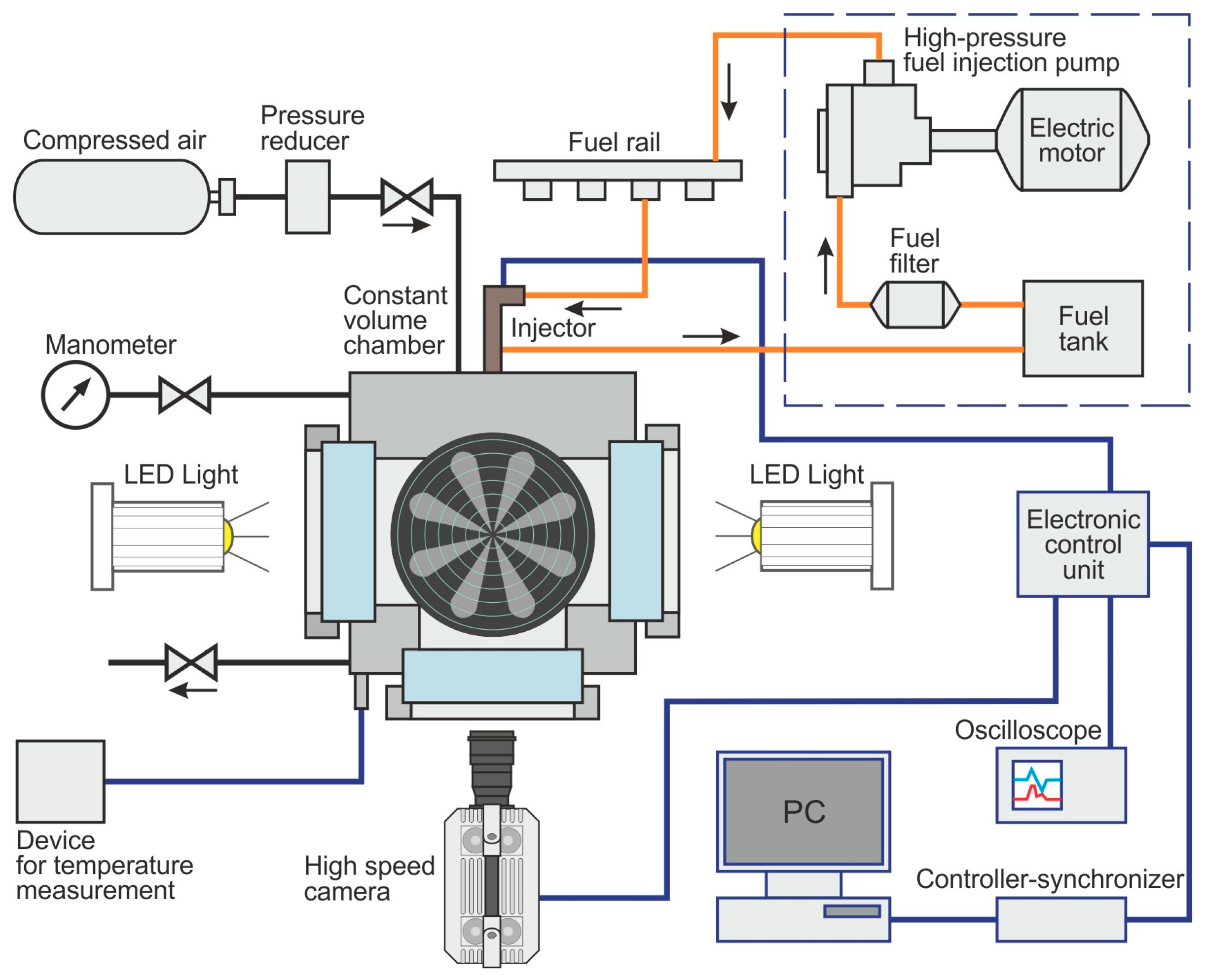
2.1. Experimental Setup.

The South Ural State University has developed and manufactured a test stand with a constant volume chamber and high-speed video camera [29]. It is intended for a comprehensive study of the process of fuel spray formation and the fuel distribution in combustion chamber for diesel engines of various capacities. This stand is designed taking into account world experience in the field of modeling [30,31,32] and conducting experimental studies with visualization of the processes of injection, atomization, and mixture formation [2,33].
Schematic of the experimental setup is shown in Figure 5. It has the following systems: Common Rail fuel injection system, air supply from a compressed air bottle, constant volume chamber, pressure and temperature measurements of the air/fuel mixture, control unit of stand equipment, control signal recording system, and high-speed camera.
The experimental setup includes a universal constant volume camera with an internal diameter of 150 mm (Figure 6). It is designed to work under gas pressure up to 10 MPa. The chamber has three windows of high-strength quartz glass for illumination and high-speed video filming of the motion of the atomized fuel spray. Electromagnetic injector is installed at the bottom, opposite the front window. LED lights illuminate the fuel sprays through the side windows of the chamber (Figure 7).
Diesel fuel is supplied from the fuel stand HY-EPS200 of Taian Haiyu Machinery Co., Ltd. (Figure 7). The rail pressure is set and regulated in the range from 100 to 200 MPa.
The test stand management system includes a personal computer (PC), a synchronization controller, and an electronic control unit (Figure 7). A special program provides control and synchronization of pulses to control an electromagnetic injector, a Photron FASTCAM SA-X2 speed video camera, and a Tektronix TDS-2014C 4-channel digital color oscilloscope.

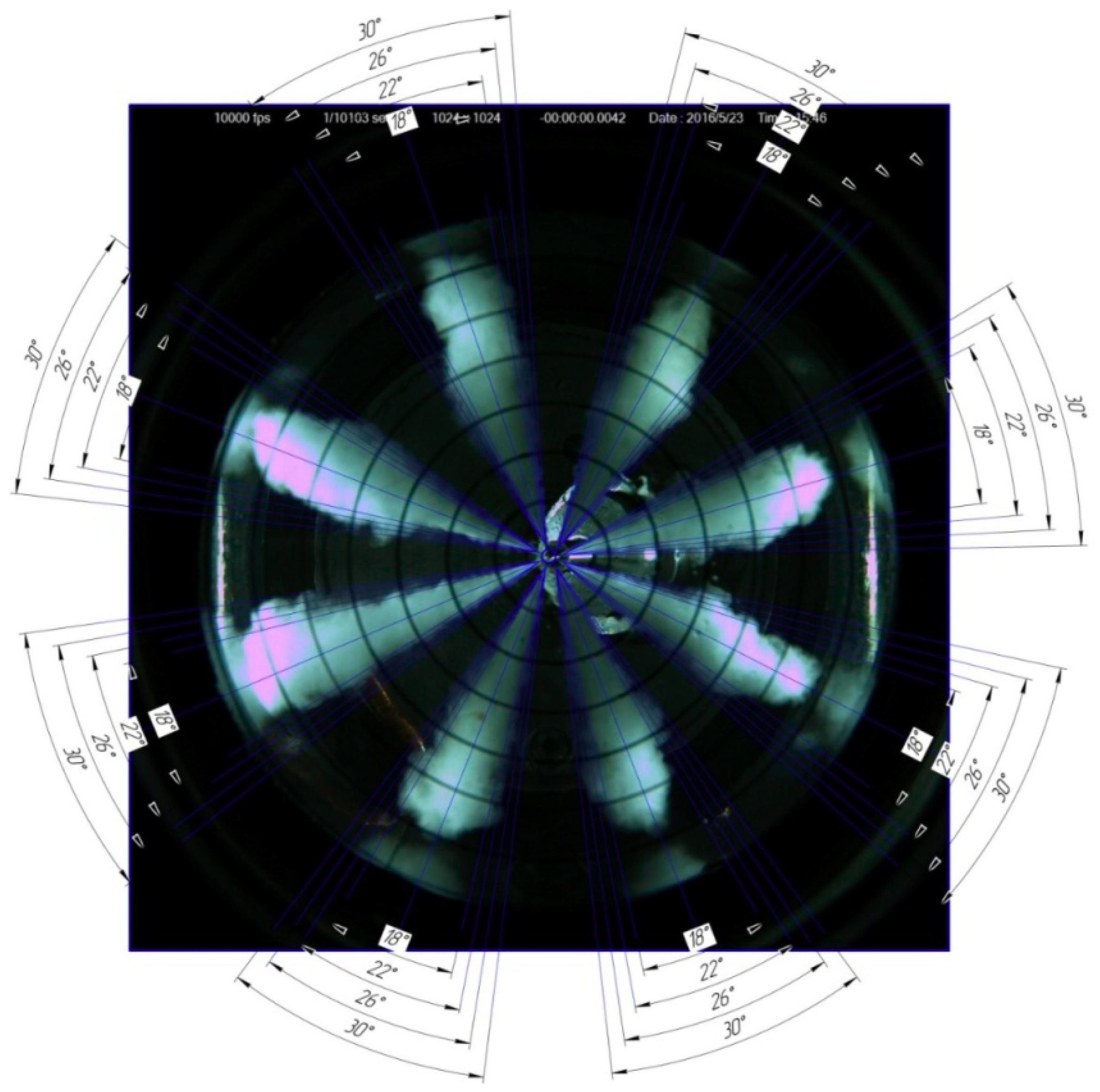
2.2. Experimental Research Methodology.

In the course of experimental studies, comparative tests of electromagnetic injectors with nozzles 1 and 2 were carried out (Figure 4 and Table 1). At the same time, the delay duration of the actual beginning and the actual end of fuel injection, the dynamics of changes in the fuel spray penetration, the fuel spray cone angles, and the magnitude of the cyclic fuel supply at different rail pressures were determined.
The duration of injector control pulse was set to 1.5 ms. The initial rail pressure was set at 100, 130, and 165 MPa. The air pressure in the constant volume chamber was maintained at 3.0 MPa at a temperature of about 20 °C.
The real time moments of the beginning and end of fuel injection by the electromagnetic injector were determined by the photographic results from the FASTCAM SA-X2 video camera and were counted from its beginning. Time control was carried out by recording control pulses on a Tektronix TDS-2014C digital oscilloscope (Figure 2). The camera operated at 10,000 frames per second, producing images every 0.1 ms during the injection event. The results were saved in photo format.
In all the photographs, the penetration length for each spray was determined as the maximum distance from the nozzle orifice exit to the spray tip after 0.1 ms. Auxiliary circles, which are applied to the frontal window inside chamber along the radius by steps of 10 mm from the center of nozzle tip, were used as rulers (Figure 8). The spray cone angles were measured by using special templates with marked angles (18°, 22°, 26°, and 30°) (Figure 8). Angles were measured from photographs taken when the sprays reached the chamber wall.
The diesel fuel mass delivery per cycle was determined by the volumetric method according to the amount of fuel supplied through an electromagnetic injector for 30 cycles. This fuel was drained from a constant volume chamber into a special measuring container.

3. Results

During the tests, in each experiment, a high-speed video was taken for 5.0 ms and 50 frames were recorded. Thus, for the nozzles 1 and 2, in all the studied modes, the photo of fuel sprays in the corresponding developmental stage was taken every 0.1 ms. Fuel sprays appeared in 0.3–0.4 ms after the start of the electric control pulse of the electromagnetic injector, that is, third or fourth photos [34]. The length of the fuel sprays on each of the next photo increased by 2–5 mm. The outflow of fuel from the nozzle orifices continued for 1.0 ms after the termination of the control pulse. The actual duration of fuel injection was 2.1–2.2 ms for a given control pulse duration of 1.5 ms.
Figure A1 shows photographs of fuel sprays for nozzles 1 and 2 at a rail pressure of 100 MPa after 1.0, 1.5, and 1.8 ms from the beginning of the injection of the injector control pulse. Fuel sprays are clearly visible in the initial stage of formation, then in the middle stage of development, and immediately after the end of the control pulse.
A similar selection of photo fuel sprays for nozzles 1 and 2 is shown in Figure A2 with a rail pressure of 130 MPa. It also shows the photos in the initial stage of injection, after 1.5 and 1.8 ms from the beginning.
Figure A3 shows the photo of fuel sprays at the same time points for both injectors at a rail pressure of 165 MPa. In the last photo, fuel sprays 4 and 5 reach the walls of the constant volume chamber.
In all photos, after 1.8 ms from the beginning of the control pulse the fuel continues to flow through the nozzle orifices.

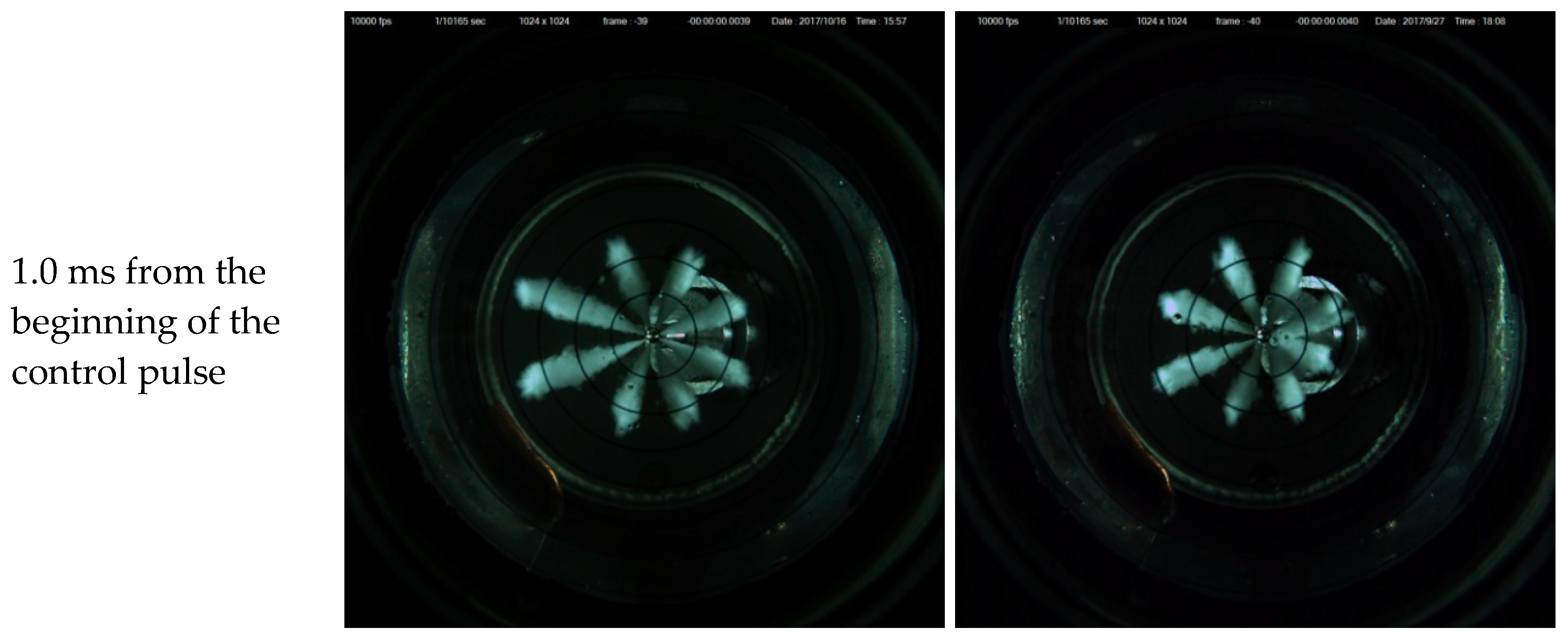
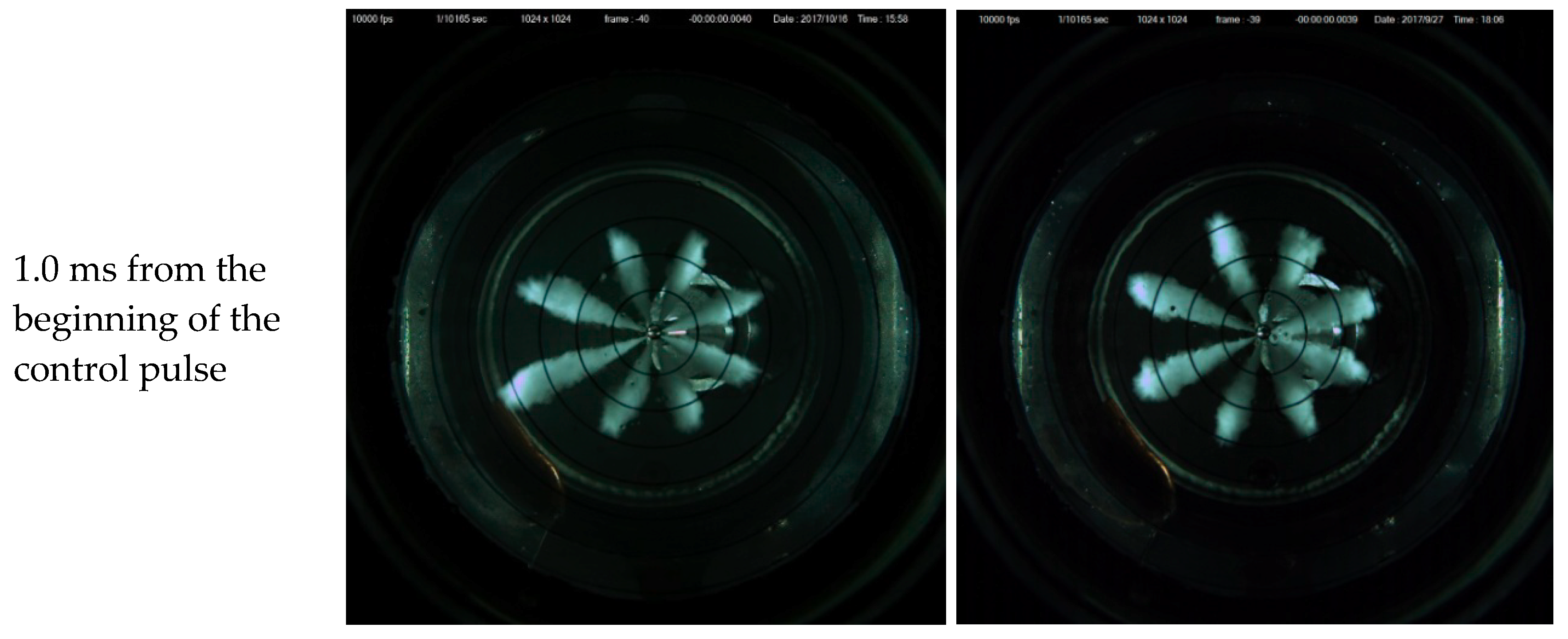
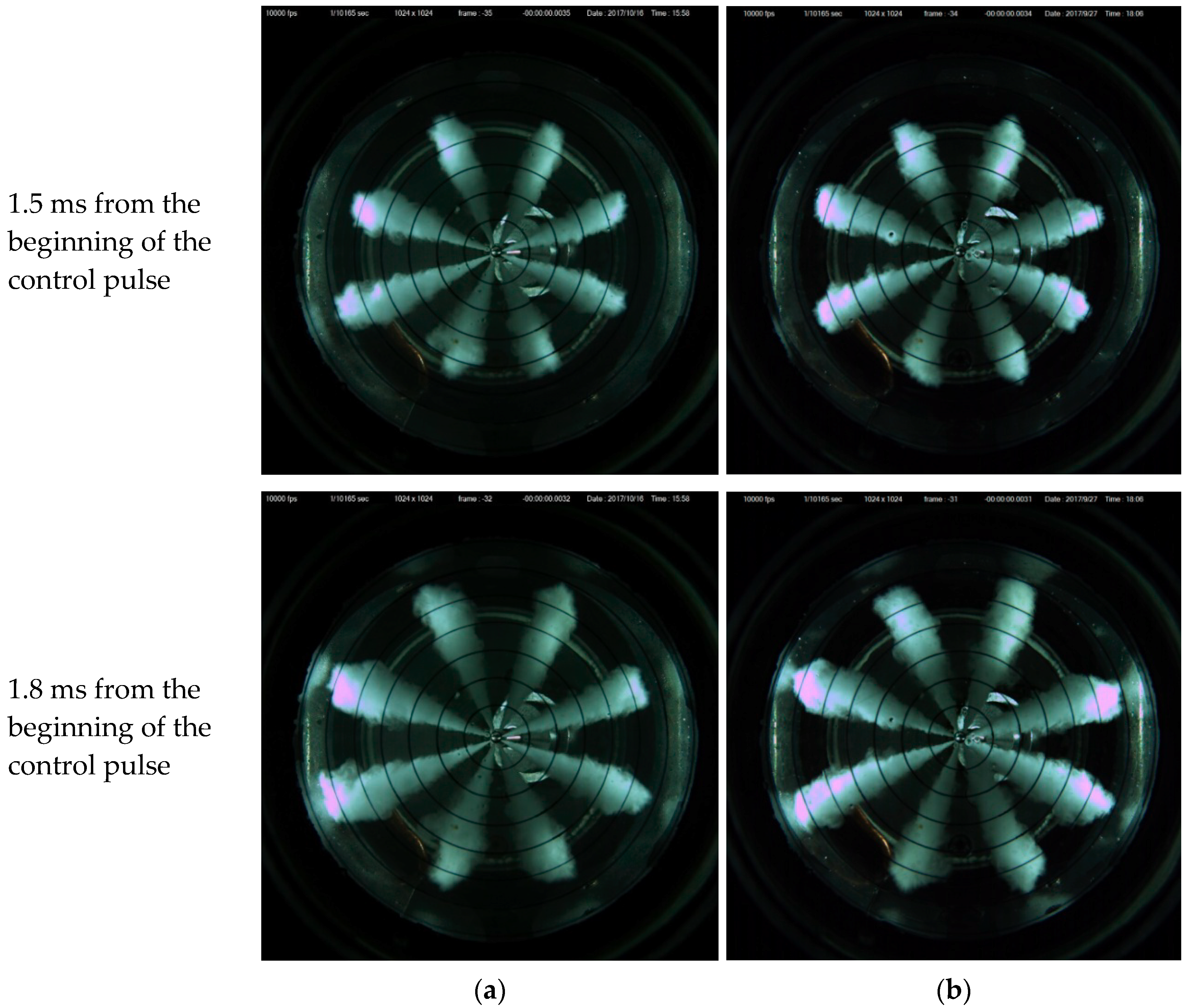
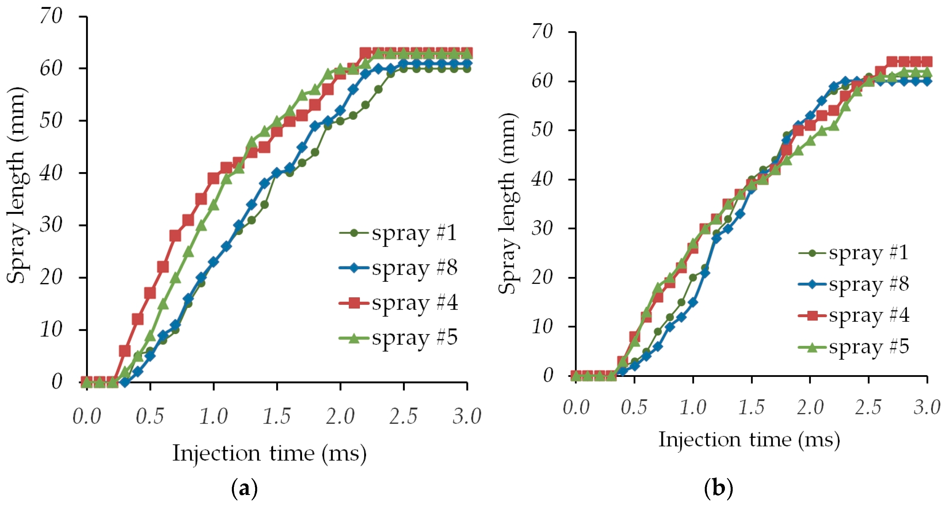
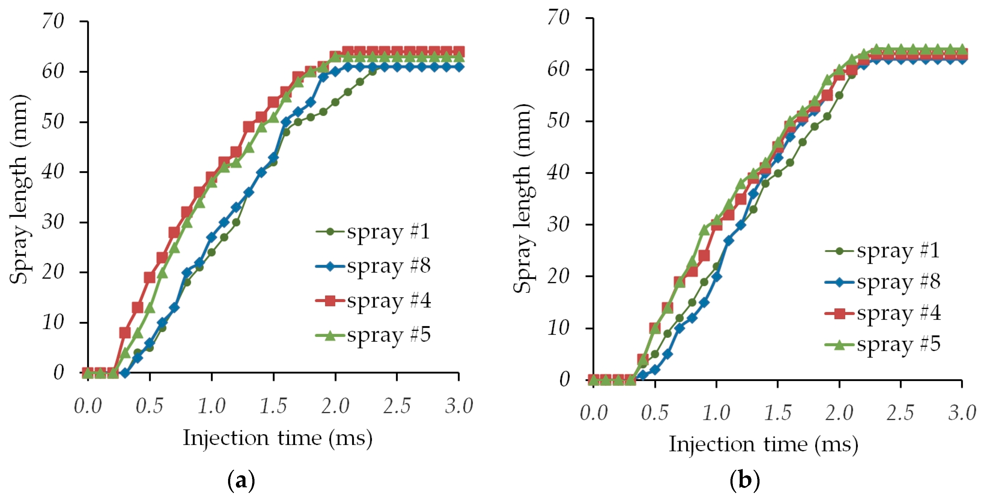
3.1. The Results of Measuring the Length of Fuel Sprays.

The results of the experiments show that for the nozzle 1, the sprays from holes 4 and 5 have the greatest length. The axes of these spray holes are inclined from the axis of the nozzle by an angle of about 30°. While the shortest fuel sprays lie in holes 1 and 8, the axes of which are inclined from the axis of the nozzle by an angle of about 100°.
Using numerical tabular values, diagrams of the change in the length of fuel sprays numbered 1, 8 and 4, 5 for nozzle 1 and 2 were plotted (Figure 9, Figure 10 and Figure 11). When the rail pressure was 100 MPa (Figure 9) for the nozzle 1, the fuel sprays 4 and 5 at the time of 1.0 ms from the beginning of the control pulse had a length of 30 and 26 mm, which were almost two times longer than the other sprays (15–20 mm). This length difference of sprays in 10 mm was maintained throughout the injection until sprays arrived at the wall of the chamber. This is clearly seen in Figure 9a. At nozzle 2, the fuel sprays 4 and 5 at a time of 1.0 ms from the beginning of the control pulse had a length of about 25 mm, which exceeded the remaining sprays by an average of 5 mm. By the time 1.8 ms, the difference in length was leveled (Figure 9b). For the nozzle 1, the fuel sprays 4 and 5 reached the chamber walls in 2–2.2 ms, and the sprays 1 and 8 fell behind by 0.3–0.5 ms. For nozzle 2, the fuel sprays 4 and 5 reached the chamber walls in 2.5–2.7 ms, and the sprays 1 and 8—earlier by 0.4–0.5 ms.
With a rail pressure of 130 MPa, the overall picture of the development of sprays is preserved (Figure A2). At the nozzle 1, the fuel sprays 4 and 5 at a time of 1.0 ms from the beginning of the control pulse had a length of about 35 mm, and the remaining sprays were 22 to 26 mm. The length difference exceeded 10 mm and persisted throughout the injection (Figure 10a). At nozzle 2, the fuel sprays 4 and 5 at a time of 1.0 ms from the beginning of the control pulse had a length of about 30 mm, which was 3 to 5 mm longer than the other sprays. By the time of 1.8 ms, the length difference decreased to 2–3 mm (Figure 10b). For the nozzle 1, the fuel sprays 4 and 5 reached the chamber walls in ~2 ms, and the sprays 1 and 8 were 0.1–0.3 ms behind (Figure 10). For nozzle 2, all fuel plumes reached the chamber wall in 2.2–2.3 ms.
With a fuel pressure of 165 MPa (Figure A3) for the nozzle 1, the fuel sprays 4 and 5 at a time of 1.0 ms from the beginning of the control pulse had a length of 35 and 44 mm, and the remaining sprays were 26–28 mm. The length difference reached 15 mm and persisted throughout the injection (Figure 11a). At nozzle 2, the fuel sprays 4 and 5 at a time of 1.0 ms from the beginning of the control pulse had a length of about 35–38 mm, which was 3 to 5 mm longer than the remaining sprays. By the time 1.8 ms, the length difference reduced to 2–3 mm (Figure 11b). For the nozzle 1, the fuel sprays 4 and 5 reached the chamber walls in 1.7–1.8 ms, and the sprays 1 and 8 fell behind by 0.3–0.5 ms. For the nozzle 2, the fuel sprays 4 and 5 reached the chamber walls in 1.8–1.9 ms, and the sprays 1 and 8 fell behind by ~0.2 ms.

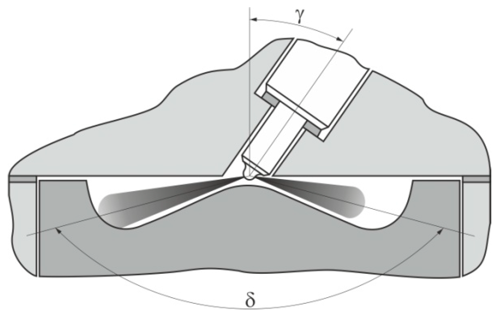
3.2. The Results of Measuring the Cone Angles of Fuel Sprays.

In the photographs (Figure A1, Figure A2 and Figure A3), the visible contours of the fuel sprays had irregularities, significant curvatures, and differ significantly in shape from the geometric cone. This is caused by turbulent flows at the interface of the fuel spray with compressed air. However, in the first approximation, the shape of the spray of the atomized fuel is generally presented in the form of a cone. Therefore, the determination of the angle of the cone of the fuel sprays was carried out along the midline of the outer surface without fluctuations. The measured angles of the cones of the fuel sprays at rail pressures of 100, 130, and 165 MPa for each spray were entered in the table.
The results in Table 2 and Table 3 show that with increasing rail pressure from 100 to 165 MPa, the cone angles of fuel sprays of the nozzle 1 decrease from 20–22° to 18–18.5°, an average of 13.6%. The cone angles of fuel sprays of the nozzle 2 are reduced from 20–24° to 19–22.5°, an average of 5.7%.

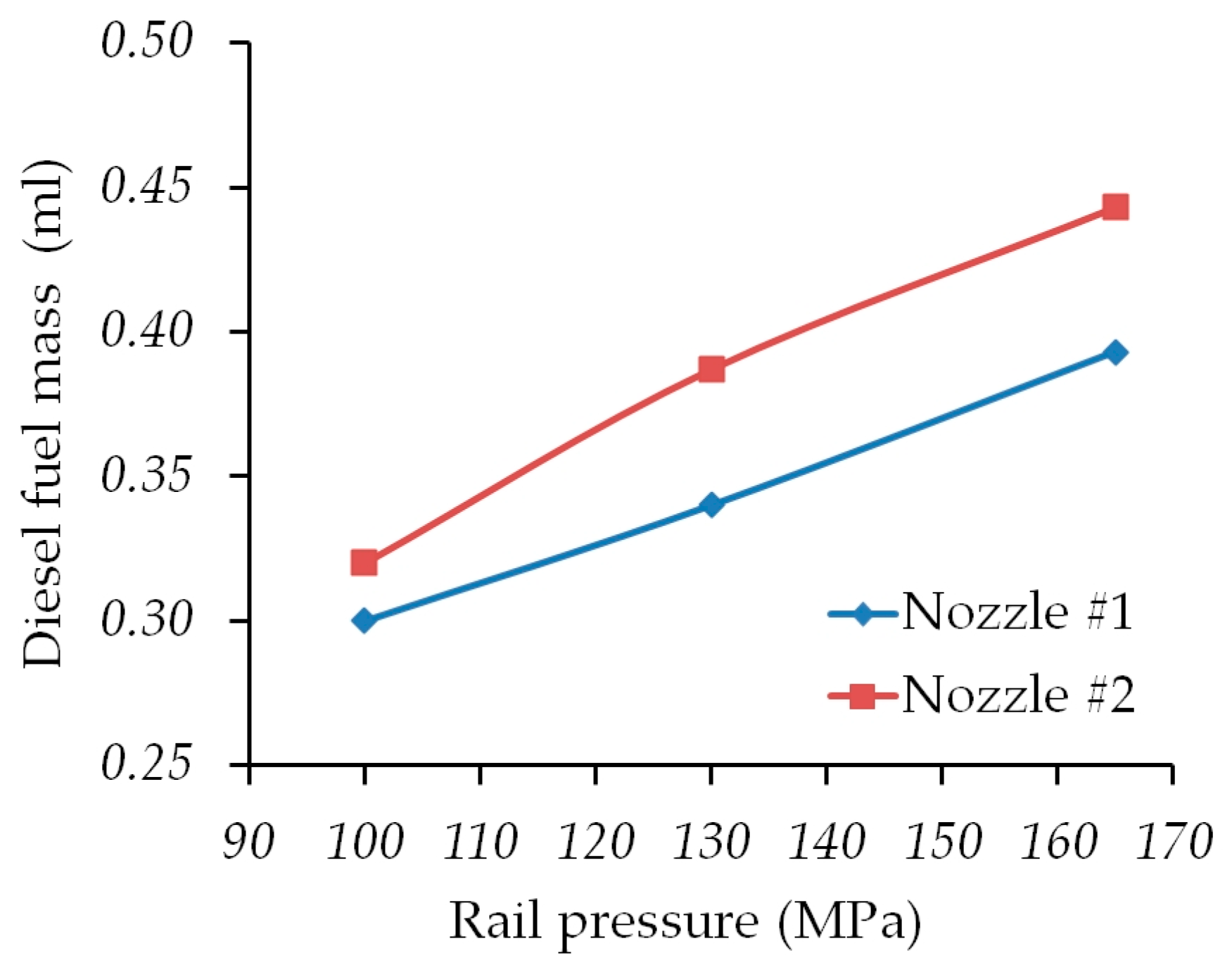
3.3. The Results of Measurement of the Cyclic Fuel Supply by the Electromagnetic Injector of Common Rail type with Nozzles 1 and 2

The measured volumes of the fuel collected by measured fuel capacities at rail pressures of 100, 130, and 165 MPa for each nozzle were entered in Table 4.
From the obtained values, the calculation determined the cyclic fuel supply for one injection for each nozzle (Table 5).
According to Table 5, diagrams of changes in the volumetric cycle fuel supply for nozzles 1 and 2 at different rail pressure (Figure 12) are plotted.
The results given in Table 5 and in Figure 12 show that with an increase of rail pressure from 100 to 165 MPa, the volumetric cycle fuel supply using the nozzle 1 increases by 31%, for the nozzle 2—by 38.4%.

4. Discussion

The obtained photographs of the fuel sprays injected by the obliquely installed Common Rail injector showed that the fuel sprays for eight holes of nozzle all develop differently. This is caused both by the different position of the spray holes to the injector axis (Figure 1 and Figure 3) and by the different diameters of the spray holes (Table 1). The influence of the position of the spray holes is significant on the reference of results obtained from the nozzle 1. In Figure A1a, Figure A2a, and Figure A3a it is clear that all the fuel sprays 4 and 5 are the longest, and the fuel sprays 1 and 8 are the shortest. With an equal diameter of the spray holes, this is explained only by the different dynamics of the movement of fuel in the tip of the nozzle. The direction of fuel movement in the spray holes 4 and 5 has a slight deviation from the general direction of movement in the nozzle (about 30°). And the direction of movement in holes 1 and 8 turns 100° from the general direction, almost in the opposite direction. The nature of the movement in the remaining spray holes is determined by their intermediate position, and the differences in the development of their fuel sprays are not significant.
The effect of the diameter of the spray holes is observed in the results obtained from the nozzle 2. In Figure A1b, Figure A2b, and Figure A3b the fuel sprays 4 and 5 only slightly (by 2–3 mm) exceed the length of the others. In the same place, the fuel sprays 1 and 8 in some cases exceed the length of the sprays 3 and 6. Thus, increasing diameters of the nozzle orifices 1, 2, 7, and 8 (Table 1) reduces the development differences between fuel sprays. That is, an increase in the diameters of the spray orifices made a compensation for the deviation of the flow of fuel in them from the axis of the nozzle.
Diagrams of the change in the average length of the fuel sprays for nozzles 1 and 2 at rail pressures of 100, 130, and 165 MPa (Figure 13) are shown below. The average sprays development rates were determined and evaluated by using these data.
The length of the fuel sprays increases faster at the initial injection site within 1.0 ms. The estimated change rate of the average length of the fuel sprays is from 35 (at 100 MPa) to 50 m/s (at 165 MPa) [34], then it decreases to 31 and 38 m/s, respectively. As a result, the spray length reaches 60 mm after 2.4–2.5, ~2.1, and ~1.7 ms from the beginning of control pulse depending on the injection pressure.
With an injection pressure of 100 MPa (Figure 13a), the average development rate of the fuel sprays of the nozzle 2 is about 31 m/s, which is less than nozzle 1 (about 34 m/s). But the lengths of all sprays differ slightly (Figure A1b). That is, the fuel is more evenly distributed in the combustion chamber. In this case, the rate of mixing is somewhat less. However, the lag in the development of fuel sprays is only about 0.1 ms. With an injection pressure of 130 MPa, the average development rate of the fuel sprays of the nozzle 2 increases to ~35 m/s (i.e., by 4 m/s). In nozzle 1, this rate also increases by a smaller value of ~2 m/s, and is about 36 m/s. The lag in the development of fuel sprays in the nozzle 2 is less than 0.1 ms. When the injection pressure is 165 MPa, the average development rate of the fuel sprays of the nozzle 2 increases even more—by 5 m/s and reaches about 40 m/s, and in nozzle 1, this rate increases by a smaller value—4 m/s. As a result, the average rate of fuel spray development are equalized in size and are about 40 m/s. This provides almost the same dynamics of their development.
The different positions of the spray orifices with respect to the injector axis and their diameter are also reflected in the measuring results of fuel spray cone angle. With a rail pressure of 100 MPa at the nozzle 1 (Table 2) with equal orifice diameters, the values of the measured fuel spray cone angles differ by 1.5°. At rail pressures of 130 and 165 MPa, the angle difference is 1.5° and 0.5°. As a rule, large-angle fuel sprays are injected from nozzle orifices 1, 2 and 7, 8. They also have the smallest lengths. For nozzle 2 (Table 3) with different orifice diameter (Table 1), the values of the measured fuel spray cone angle at rail pressure of 100 MPa differ by 3.0°. At rail pressures of 130 and 165 MPa, the angle difference is 4.0° and 3.5°. Large-angle fuel sprays are also injected from nozzle orifices 1, 2 and 7, 8. However, the length of these sprays from the nozzle 2 is slightly different from the others. The average values of fuel spray cone angle are given in Table 6. Here it can be seen that at all values of the rail pressure, in the nozzle 2 there are larger cone angles (from 2.65% to 11.9%). Taking into account the fact that the development of fuel sprays in the nozzle 2 is slightly less, we can expect an increase in the volume occupied by the fuel in the Hesselman-type combustion chamber and an improvement in the mixture formation and combustion.
The use of increased diameters of the nozzle orifices in the injector 2 leads to a significant increase of the diesel fuel mass delivery per cycle (from 6.7% to 13.7%) (Table 5). That is, in the increased volume of fuel sprays there is a greater amount of fuel. To reduce the injected fuel quantity, it is enough to reduce control pulse width to the Common Rail diesel injector. Experimental studies have shown that in this case, the dynamics of development of fuel sprays practically does not decrease. However, in order to clarify the ratio of fuel and air and its effect on the operating process of a diesel engine with an inclined injector position, additional studies of the processes of mixture formation and combustion on a real diesel engine are necessary.

5. Conclusions

In this paper, a diesel electromagnetic injector with two eight-hole nozzles was investigated: Nozzle 1 with identical orifices diameter of 0.30 mm and nozzle 2 with four orifices of the same diameter of 0.30 mm and four orifices of enlarged diameters. In order to realize fuel injection visualization, a constant volume chamber with a diameter of 150 mm was designed. The chamber allows observation of the complete fuel spray pattern of the diesel injectors. Fuel was injected at common rail pressure from 100 to 165 MPa and the duration of electric injector control pulse 1.5 ms. The obtained results can be summarized as follows:
-
Delay in the start of the fuel injection process from the initial moment of the electric impulse controlling the injector, regardless of rail pressure, was about 0.3 ms;
-
Delay in the end of the fuel injection process from the end of the electric impulse controlling the injector, regardless of rail pressure, was about 1.0 ms;
-
Duration of the fuel injection process is usually 0.7 ms longer than the duration of the electric impulse controlling the injector;
-
At nozzle 1, the fuel sprays develop differently: The sprays from nozzles 4 and 5 have the greatest penetration length; the difference of spray penetration length with other nozzles reaches 10–15 mm and persists until it touches the chamber wall;
-
At nozzle 2, the fuel sprays develop more evenly: The greatest difference in spray penetration length of nozzles 4 and 5 with others is no more than 3–5 mm;
-
Average development rate of the fuel sprays of the nozzle 2 at a rail pressure of 100 MPa is 3 m/s less than that of the nozzle 1 (31 and 34 m/s, respectively), but as the pressure rises to 165 MPa, the velocities equalize and are about 40 m/s;
-
The measured fuel spray cone angles from the nozzle orifices 1, 2, 7, and 8 are usually larger than the angles from the other orifices: For nozzle 1, this difference is from 0.5° to 1.5°, and for nozzle 2 it reaches 3.0–4.0°;
-
With increase in rail pressure from 100 to 165 MPa, the fuel spray cone angles of the nozzle 1 decrease from 20–22° to 18–18.5°, by an average of 13.6%. The fuel spray cone angles of the nozzle 2 are reduced from 20–24° to 19–22.5°, by an average of 5.7%.
When the injector is inclined and the diameters of the nozzle orifices are same, the distribution of fuel over the combustion chamber is uneven. Differential increase in the diameters of nozzle orifices, the axes of which are maximally deviated from the injector axis, will reduce this irregularity and improve the processes of mixing in a diesel engine with the Hesselman combustion chamber. The use of diesel injectors with such nozzles will improve the combustion efficiency and improve the environmental performance of the diesel engine.

Author Contributions

V.G.K conceived concept and designed experiment, wrote the original draft paper; V.A.M. provided formal analysis of results; I.O.L. performed the experiment and processing of results; A.A.Z. provided editorial contribution; V.V.F. provided the project administration and resources.

Funding

This research received no external funding.

Conflicts of Interest

The authors declare no conflict of interest.

Appendix A

Figure A1. Development of fuel sprays in a constant volume chamber with nozzle 1 (a) and nozzle 2 (b) with a rail pressure of 100 MPa.
Energies 12 02643 g0a1aEnergies 12 02643 g0a1b
Figure A2. Development of fuel sprays in a constant volume chamber with nozzle 1 (a) and nozzle 2 (b) with a rail pressure of 130 MPa.
Energies 12 02643 g0a2aEnergies 12 02643 g0a2b
Figure A3. Development of fuel sprays in a constant volume chamber with nozzle 1 (a) and nozzle 2 (b) with a rail pressure of 165 MPa.
Energies 12 02643 g0a3aEnergies 12 02643 g0a3b

References

  1. Payri, R.; Bracho, G.; Marti-Aldaravi, P.; Viera, A. Near field visualization of diesel spray for different nozzle inclination angles in non-vaporizing conditions. At. Sprays 2017, 27, 251–267. [Google Scholar] [CrossRef]
  2. Herfatmanesh, M.R.; Lu, P.; Attar, M.A.; Zhao, H. Experimental investigation into the effects of two-stage injection on fuel injection quantity, combustion and emissions in a high-speed optical common rail diesel engine. Fuel 2013, 109, 137–147. [Google Scholar] [CrossRef] [Green Version]
  3. Payri, R.; Salvador, F.J.; Bracho, G.; Viera, A. Differences between single and double-pass schlieren imaging on diesel vapor spray characteristics. Appl. Therm. Eng. 2017, 125, 220–231. [Google Scholar] [CrossRef]
  4. Wang, Z.; Xu, H.; Jiang, C.; Wyszynski, M.L.W. Experimental study on microscopic and macroscopic characteristics of diesel spray with split injection. Fuel 2016, 174, 140–152. [Google Scholar] [CrossRef]
  5. Payri, R.; Salvador, F.J.; Bracho, G.; Viera, A. Vapor phase penetration measurements with both single and double-pass Schlieren for the same injection event. In Proceedings of the ILASS–Europe 2017 28th Conference on Liquid Atomization and Spray Systems, Valencia, Spain, 6–8 September 2017; Payri, R., Margot, X., Eds.; Editorial Universitat Politecnica de Valencia: Valencia, Spain, 2017. [Google Scholar]
  6. Payri, R.; Viera, J.P.; Gopalakrishnan, V.; Szymkowicz, P.G. The effect of nozzle geometry over internal flow and spray formation for three different fuels. Fuel 2016, 183, 20–33. [Google Scholar] [CrossRef] [Green Version]
  7. Xue, F.; Luo, F.; Cui, H.; Moro, A.; Zhou, L. Numerical analyses of transient flow characteristics within each nozzle hole of an asymmetric diesel injector. Int. J. Heat Mass Transf. 2017, 104, 18–27. [Google Scholar] [CrossRef]
  8. Salvador, F.J.; Jaramillo, D.; Romero, J.-V.; Rosello, M.-D. Using a homogeneous equilibrium model for the study of the inner nozzle flow and cavitation pattern in convergent–divergent nozzles of diesel injectors. J. Comput. Appl. Math. 2017, 309, 630–641. [Google Scholar] [CrossRef]
  9. Hansen, H.; Jollet, S.; Niemeyer, D.; Thimm, L.; Dinkelacker, F. Influence of the spray hole geometries on cavitation formation inside diesel injector nozzles. In Proceedings of the 2nd Conference on Engine Processes, Berlin, Germany, 2–3 July 2015; Sens, M., Baar, R., Eds.; Universitätsverlag der TU Berlin: Berlin, Germany, 2015; pp. 158–168. [Google Scholar]
  10. Salvador, F.J.; Carreres, M.; Jaramillo, D.; Martinez-Lopez, J. Analysis of the combined effect of hydrogrinding process and inclination angle on hydraulic performance of diesel injection nozzles. Energy Convers. Manag. 2015, 105, 1352–1365. [Google Scholar] [CrossRef] [Green Version]
  11. Algayyim, S.J.M.; Wandel, A.P.; Yusaf, T. The Impact of Injector Hole Diameter on Spray Behaviour for Butanol-Diesel Blends. Energies 2018, 11, 1298. [Google Scholar] [CrossRef]
  12. Eagle, E.W.; Morris, S.B.; Wooldridge, M.S. High-speed imaging of transient diesel spray behavior during high pressure injection of a multi-hole fuel injector. Fuel 2014, 116, 299–309. [Google Scholar] [CrossRef]
  13. Payri, R.; Gimeno, J.; Bracho, G.; Vaquerizo, D. Study of liquid and vapor phase behavior on Diesel sprays for heavy duty engine nozzles. Appl. Therm. Eng. 2016, 107, 365–378. [Google Scholar] [CrossRef] [Green Version]
  14. Yu, S.; Yin, B.; Deng, W.; Jia, H.; Ye, Z.; Xu, B.; Xu, H. Experimental study on the spray characteristics discharging from elliptical diesel nozzle at typical diesel engine conditions. Fuel 2018, 221, 28–34. [Google Scholar] [CrossRef]
  15. Yu, S.; Yin, B.; Deng, W.; Jia, H.; Ye, Z.; Xu, B.; Xu, H. Experimental study on the diesel and biodiesel spray characteristics emerging from equilateral triangular orifice under real diesel engine operation conditions. Fuel 2018, 224, 357–365. [Google Scholar] [CrossRef]
  16. Yu, S.; Yin, B.; Deng, W.; Jia, H.; Ye, Z.; Xu, B.; Xu, H. An experimental comparison of the elliptical and circular nozzles spray and mixing characteristics under different injection pressures. Fuel 2019, 236, 1474–1482. [Google Scholar] [CrossRef]
  17. Yu, S.; Yin, B.; Deng, W.; Jia, H.; Ye, Z.; Xu, B.; Xu, H. Experimental study on the spray and mixing characteristics for equilateral triangular and circular nozzles with diesel and biodiesel under high injection pressures. Fuel 2019, 239, 97–107. [Google Scholar] [CrossRef]
  18. Desantes, J.M.; Pastor, J.V.; García-Oliver, J.M.; Briceño, F.J. An experimental analysis on the evolution of the transient tip penetration in reacting Diesel sprays. Combust. Flame 2014, 161, 2137–2150. [Google Scholar] [CrossRef]
  19. Du, W.; Lou, J.; Yan, Y.; Bao, W.; Liu, F. Effects of injection pressure on diesel sprays in constant injection mass condition. Appl. Therm. Eng. 2017, 121, 234–241. [Google Scholar] [CrossRef]
  20. Xia, J.; Huang, Z.; Xu, L.; Ju, D.; Lu, X. Experimental study on spray and atomization characteristics under subcritical, transcritical and supercritical conditions of marine diesel engine. Energy Convers. Manag. 2019, 195, 958–971. [Google Scholar] [CrossRef]
  21. Payri, R.; Giraldo, J.S.; Ayyapureddi, S.; Versey, Z. Experimental and analytical study on vapor phase and liquid penetration for a high pressure diesel injector. Appl. Therm. Eng. 2018, 137, 721–728. [Google Scholar] [CrossRef]
  22. Pinkert, F.; Najar, I.; Drescher, M.; Fink, C.; Harndorf, H. Nozzle geometry impact on spray, ignition and combustion of large fuel injection jets. In Proceedings of the 2nd Conference on Engine Processes, Berlin, Germany, 2–3 July 2015; Sens, M., Baar, R., Eds.; Universitätsverlag der TU Berlin: Berlin, Germany, 2015; pp. 140–157. [Google Scholar]
  23. Soid, S.N.; Zainal, Z.A. Spray and combustion characterization for internal combustion engines using optical measuring techniques—A review. Energy 2011, 36, 724–741. [Google Scholar] [CrossRef]
  24. Huang, H.; Liu, Q.; Shi, C.; Wang, Q.; Zhou, C. Experimental study on spray, combustion and emission characteristics of pine oil/diesel blends in a multi-cylinder diesel engine. Fuel Process. Technol. 2016, 153, 137–148. [Google Scholar] [CrossRef]
  25. Salvador, F.J.; Lopez, J.J.; De la Morena, J.; Crialesi-Esposito, M. Experimental investigation of the effect of orifices inclination angle in multihole diesel injector nozzles. Part 1–Hydraulic performance. Fuel 2018, 213, 207–214. [Google Scholar] [CrossRef]
  26. Payri, R.; Salvador, F.J.; De la Morena, J.; Pagano, V. Experimental investigation of the effect of orifices inclination angle in multihole diesel injector nozzles. Part 2–Spray characteristics. Fuel 2018, 213, 215–221. [Google Scholar] [CrossRef]
  27. Payri, R.; Gimeno, J.; Bardi, M.; Plazas, A.H. Study liquid length penetration results obtained with a direct acting piezo electric injector. Appl. Energy 2013, 106, 152–162. [Google Scholar] [CrossRef] [Green Version]
  28. Kowalski, J. Influence of fuel injector holes diameter on parameters of combustion process in the cylinder of the marine 4-stroke Diesel engine. J. Pol. CIMEEAC 2016, 11, 95–102. [Google Scholar]
  29. “Injection”: Unique Research Installation. Available online: https://sites.susu.ru/inject/ (accessed on 1 June 2019).
  30. Musculus, M.P.B.; Miles, P.C.; Pickett, L.M. Conceptual models for partially premixed low-temperature diesel combustion. Prog. Energy Combust. Sci. 2013, 39, 246–283. [Google Scholar] [CrossRef]
  31. Seykens, X.L.J.; Somers, L.M.T.; Baert, R.S.G. Detailed modeling of common rail fuel injection process. MECCA 2005, 3, 30–39. [Google Scholar]
  32. Postrioti, L.; Buitoni, G.; Pesce, F.C.; Ciaravino, C. Zeuch method-based injection rate analysis of a common-rail system operated with advanced injection strategies. Fuel 2014, 128, 188–198. [Google Scholar] [CrossRef]
  33. Klein-Douwel, R.J.H.; Frijters, P.J.M.; Somers, L.M.T.; de Boer, W.A.; Baert, R.S.G. Macroscopic diesel fuel spray shadowgraphy using high speed digital imaging in a high-pressure cell. Fuel 2007, 86, 1994–2007. [Google Scholar] [CrossRef]
  34. Kamaltdinov, V.G.; Rozhdestvensky, Y.V.; Lysov, I.O.; Popov, A.Y.; Nikiforov, S.S. Experimental Investigations of the Effects of Electric Control Impulse on Injection Characteristics of Common Rail Type Injector. Indian J. Sci. Technol. 2016, 9, 104225. [Google Scholar] [CrossRef]
Figure 1. Installation of a fuel injector with a slope angle γ in a diesel engine.
Energies 12 02643 g001
Figure 2. Oscillogram of control of the solenoid injector and high-speed camera: 1—Starting voltage of control unit; 2—control pulse of high-speed camera; 3—voltage on the solenoid valve of injector; 4—output voltage of current transducer LTS 25-NP.
Energies 12 02643 g002
Figure 3. Numbering of orifices of the nozzles examined.
Energies 12 02643 g003
Figure 4. Photos of nozzle 1 (a) and nozzle 2 (b).
Energies 12 02643 g004
Figure 5. Schematic of the experimental setup with a constant volume chamber and high speed camera.
Energies 12 02643 g005
Figure 6. Photograph of the constant volume chamber.
Energies 12 02643 g006
Figure 7. Photograph of the experimental setup for studying injection and mixing processes in a constant volume chamber with high-speed camera: 1—Electronic control unit; 2—controller-synchronizer; 3—personal computer; 4—oscilloscope; 5—high-speed camera; 6—constant volume chamber with LED lights; 7—stand for testing fuel equipment of Common Rail type.
Energies 12 02643 g007
Figure 8. Determination of the fuel spray cone angles by the marked angles.
Energies 12 02643 g008
Figure 9. Dynamics of change in the length of the fuel sprays 1, 8 and 4, 5 for the nozzle 1 (a) and the nozzle 2 (b) with a rail pressure of 100 MPa.
Energies 12 02643 g009
Figure 10. Dynamics of change in the length of the fuel sprays 1, 8 and 4, 5 for the nozzle 1 (a) and the nozzle 2 (b) with a rail pressure of 130 MPa.
Energies 12 02643 g010
Figure 11. Dynamics of change in the length of the fuel sprays 1, 8 and 4, 5 for the nozzle 1 (a) and the nozzle 2 (b) with a rail pressure of 165 MPa.
Energies 12 02643 g011
Figure 12. Changing the volumetric fuel cycle of the electromagnetic injector with nozzles 1 and 2 depending on the rail pressure.
Energies 12 02643 g012
Figure 13. Dynamics of change in the average lengths of the fuel sprays of injectors at rail pressures of 100 (a), 130 (b), and 165 MPa (c).
Energies 12 02643 g013
Table 1. Diameters of nozzle orifices, mm.
Hole Number12345678
Nozzle 10.300.300.300.300.300.300.300.30
Nozzle 2~0.50~0.400.300.300.300.30~0.40~0.50
Table 2. The cone angle of the fuel sprays of nozzle 1.
Rail Pressure (MPa)Hole Number
12345678
10022°22°21°21°21.5°20.5°20°21°
13020°19.5°19°19°19°19°18.5°19.5°
16518.5°18.5°18°18°18°18°18.5°18.5°
Table 3. The cone angle of the fuel sprays of nozzle 2.
Rail Pressure (MPa)Hole Number
12345678
10022.5°20°22°22°20°21°24°22°
13023°21°20°19.5°19°19°21°22°
16521°22.5°19.5°19.5°19°20°21°21°
Table 4. Volumetric fuel supplied by electromagnetic injector for 30 injections (ml).
Rail Pressure (MPa)Injector with Nozzle 1Injector with Nozzle 2Δ (%)
10099.66.7
13010.211.613.7
16511.813.312.7
Table 5. Estimated volumetric cyclic flow of fuel by the electromagnetic injector (mL).
Rail Pressure (MPa)Injector with Nozzle 1Injector with Nozzle 2Δ (%)
1000.30.326.7
1300.340.38713.7
1650.3930.44312.7
Table 6. Average values of fuel spray cone angle.
Rail Pressure (MPa)Injector with Nozzle 1Injector with Nozzle 2Δ (%)
10021.12°21.68°2.65
13019.19°20.56°7.1
16518.25°20.43°11.9

