Abstract
In the direct current (DC) microgrid composed of multiple distributed generations, due to the different distances between various converters and the DC bus in the system, the difference of the line resistance will reduce the current sharing accuracy of the system. The droop control was widely used in the operation control of the DC microgrid. It was necessary to select a large droop coefficient to improve the current sharing accuracy, but a too large droop coefficient will lead to a serious bus voltage drop and affect the power quality. In view of the contradiction between the voltage regulation and load current sharing in the traditional droop control, a hierarchical control algorithm based on the improved droop control of the fuzzy logic was proposed in this paper. By improving the droop curve, the problems of voltage regulation and current sharing were solved simultaneously. The effectiveness of the algorithm was verified by simulation.
1. Introduction
In the direct current (DC) microgrid, the DC bus voltage directly reflects the power transmission information in the system. When the DC microgrid operates in the island mode, an appropriate control strategy should be selected to stabilize the DC bus voltage [1]. The DC bus voltage stability is very important for normal operation of the DC microgrid system. At present, the droop control has become a common control mode due to its characteristics of high current sharing accuracy, plug-and-play, simple implementation and high reliability [2]. Generally, the DC/DC converter usually adopts the voltage and current double loop control method, so the DC droop control is implemented for commonly: The droop curve control is the outer loop of the voltage and current double loop control link. The reference value of the output voltage of the converter is obtained by the droop calculation. The reference value is added to the voltage and current double loop control, and then the control signal of the converter is obtained [3].
Although the droop control has many advantages, it still has its limitations that can not be ignored [4]. In the case of large differences in the line resistance, the current sharing accuracy of the system will be reduced by using the droop control. The output voltage of the traditional droop control decreases linearly with the increase of the output current, that is, the voltage regulation and current sharing between distributed generations (DGs) can not be realized simultaneously [5]. Reference [6] establishes the mixed potential function of the Buck/Boost converter, analyzes the influence of control parameters on system stability, and proposes the DC bus voltage compensation strategy. However, the stability of the DC microgrid with a single DG power supply is analyzed, and the coordinate operation of multiple DGs is not studied. Reference [7] proposes a voltage hierarchical control strategy to make the system operate stably and switch smoothly under different operation modes. However, this method does not solve the problem of the large bus voltage fluctuation, and requires high power and regulation capability of each converter. Reference [8] adopts the adaptive droop control strategy to optimize the output power of energy storage batteries under different operation modes, and proposes coordinated control strategies of three types of converters to achieve smooth switching and stable operation between different operation modes of microgrid. However, the effects of DG and system load fluctuation are not considered. Reference [9] proposes a centralized secondary control structure, in which the system voltage information is obtained by the centralized controller, and the voltage is regulated by the bottom droop control. Although this method has high control accuracy, it relies heavily on the centralized control unit and can not realize plug-and-play. References [10] and [11] propose a virtual capacitive droop control to realize the power distribution among different DGs. However, the influence of the line resistance on the power distribution characteristics of the controller is not considered, which makes it difficult for energy storage devices at different positions to respond to the unbalanced power in the system according to the set distribution scheme. Reference [12] proposes an adaptive droop control strategy. By automatically adjusting the virtual resistance of the droop controller of each energy storage unit, the automatic load power distribution and state of charge (SOC) balance between different energy storage units can be achieved, which is conducive to solving the problem of over charge and over discharge of energy storage batteries. However, the bus voltage fluctuates greatly when the power of DG and the system load fluctuate. Reference [13] proposes a double compensation method of the average voltage and current, which compensates the longitudinal intercept of the droop curve. By translating the traditional droop curve, the current distribution and voltage recovery capacity of the system can be improved at the same time. However, the control flexibility is poor, the system communication pressure also increases. References [14,15] propose an adaptive droop control strategy for the DC microgrid based on the discrete consistency algorithm. Consistent iteration is used to obtain the average voltage of the system, and the voltage regulation and current distribution are realized by adjusting the droop gain. The convergence performance is an important index of the consistency control. The convergence performance of the traditional asymptotic consistency algorithm depends on the properties of communication topology. The larger the scale of the multi-agent system is, the longer the convergence time of consistency is. At the same time, the uncertainty of communication topology is also an important factor affecting the convergence performance. In order to prolong the life of the energy storage unit and avoid overuse of one unit, the tertiary level of control should include the battery management strategy, which is used to balance the charging status of each unit [16]. Reference [17] proposes an adaptive droop control strategy based on the consistency algorithm. Current (secondary) and power (tertiary) controllers are added to the local controller to ensure the optimal operation of the DC microgrid. Reference [18] proposes a multi-stage control method based on the improved dynamic consistency algorithm. The tertiary level of control optimizes the overall conversion efficiency of the converters connected to the battery by using the average voltage recovery value calculated by the secondary control. The tertiary control structure needs to be combined with the secondary control, so the tertiary level of the control process is also a cooperative control process of iterative calculation. Through the tertiary level of control, the economy and energy efficiency of the microgrid system have been improved, but there are still limitations such as control complexity, communication delay and measurement error, and the communication safety factor needs to be optimized and improved.
Therefore, based on the improved droop control of the fuzzy logic, a hierarchical control algorithm is proposed in this paper. The proposed algorithm can improve the droop curve by outputting the corresponding virtual compensation resistance from the fuzzy logic controller and solves the problems of voltage regulation and current sharing. The proposed algorithm uses a low-speed communication system of distributed hierarchical control to obtain the voltage, current and droop coefficients of each unit in the system. For the centralized control, the redundant communication system is needed to reduce the probability of failure, but it increases the cost and complexity of the control system. The low-speed communication system of the distributed secondary control reduces the cost of the communication system, solves the drawbacks of the centralized communication system and simplifies the structure of the system. The proposed algorithm improves the autonomy, anti-interference ability and stability of the system. The effectiveness of the proposed algorithm was verified by the simulation cases.
2. DC Droop Control
2.1. Principle of DC Droop Control
The typical structure diagram of a single bus DC microgrid is shown in Figure 1.
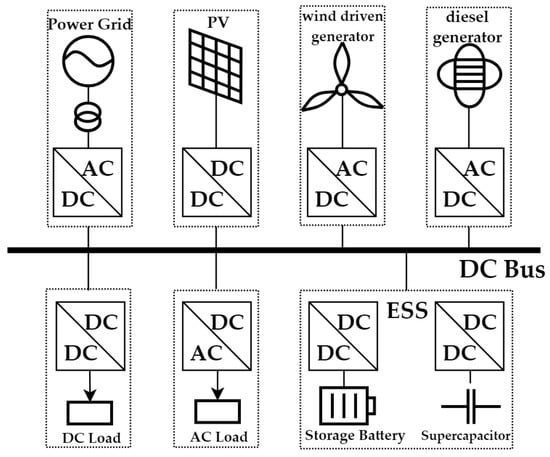
Figure 1.
The typical structure diagram of a single bus DC microgrid. PV: Photovoltaic; DC: Direct current; AC: Alternating current; ESS: Energy storage system.
According to the different ways of the DC bus voltage stability control, it can be divided into the master-slave control and peer-to-peer control [19]. In the master-slave control mode, there is only one master control unit in the DC microgrid system. The stability and reliability of the system depend entirely on the control unit. Once the unit fails, it may lead to bus voltage instability, and even lead to the DC system collapse. Thus, the reliability of the master-slave control mode is poor. Compared with the master-slave control, droop control, as the main peer-to-peer control mode, is widely used because of its simple implementation, high current sharing accuracy, plug-and-play and high reliability [20].
The block diagram of the DC droop control is shown in Figure 2 [21].
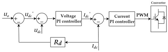
Figure 2.
The block diagram of the DC droop control. PWM: Pulse width modulation.
Among them, Udc and Idc are the output voltage and output current of the converter, Udc* and Idc* are the output reference voltage and output reference current calculated by the droop curve, Uo is the output voltage of the converter when no load is on, Rd is the virtual resistance, i.e., droop gain. The principle of the DC droop control is to calculate the reference voltage by measuring the DC current and combining the droop curve, add the reference voltage to the voltage and current double loop control, and then generate the control signal of the converter.
2.2. Limitations of DC Droop Control
Traditional droop control can carry out the proportional load distribution in the DC microgrid, and the method is simple, but at the same time it has inherent limitations. Due to the difference of the line resistance between DG and the point of common coupling (PCC) in the DC microgrid system, the output voltage of the converter is deviated, which leads to the reduction of current sharing accuracy among converters [22]. Although increasing the droop gain can improve the current sharing accuracy, it will further increase the DC bus voltage deviation [23]. Figure 3 is a simplified model of the DC microgrid system with two groups of DGs, where Rlinei (i = 1, 2) is the line resistance from the ith DG to the PCC [24].
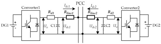
Figure 3.
DC converter parallel system structure diagram. PCC: Point of common coupling.
The expression of the U-I droop control is shown in (1). Uo is the output voltage of the converter when no load is on, and Rdi is the virtual resistance, that is, the droop gain. The droop controller uses the virtual resistance Rdi multiplied by the output current Idci to adjust the reference value of the voltage regulator.
Considering the existence of the line resistance, the following relationship can be obtained from Figure 3:
By combining (2) and (3), the relationship between the two output currents can be obtained as follows [25]:
In the traditional droop control, the output current of each converter is inversely proportional to its external characteristic resistance. If and only if Rdi >> Rlinei (i = 1, 2), the output current and the virtual resistance satisfy the following relationship:
The virtual resistance is much larger than the line resistance, it can only be realized in the ideal small DC microgrid. The increase of the droop gain improves the current sharing accuracy, but it also has the negative effect of increasing the bus voltage deviation. In the medium scale and above the DC microgrid, the droop coefficient cannot be arbitrarily increased due to the limitation of the maximum voltage deviation under the full load condition. The voltage drop through the droop resistance can be expressed as:
it can be seen from (6) that the DC bus voltage decreases with the increase of the droop resistance. The maximum droop gain is limited by the maximum allowable DC bus voltage deviation and the full load current of the converter. Therefore, the variation of droop gain Rdi should satisfy the following conditions:
among them, the ΔUim and Idcf are the maximum allowable voltage drop and full load current of the ith converter, respectively. When the line resistances are unequal, the current difference between the two modules can be reduced and the current sharing accuracy can be improved by increasing the droop gain. However, the large droop gain results in greater voltage deviation, which further deviates the DC bus voltage from its reference value [13,26]. In order to solve the inherent limitations of the traditional droop control, a hierarchical control algorithm for the DC microgrid is proposed in this paper.
3. The Hierarchical Control Algorithm Based on the Improved Droop Control of Fuzzy Logic
3.1. The Design of Fuzzy Logic Controller
3.1.1. The Fuzzy Logic Controller
The fuzzy control is a computer intelligent control based on the development of fuzzy aggregation, fuzzy linguistic variables and fuzzy logic reasoning. It is a non-linear and intelligent control system. The fuzzy control has been widely used in practical engineering [27]. Compared with the traditional control method, the control effect of the fuzzy control is better for the non-linear time-varying control object. On the one hand, the control object of the fuzzy control does not need to have a relatively accurate model. It relies on the experience of the designer in the design process of the control strategy and avoids the calculation of complex formulas. On the other hand, the establishment of the fuzzy rule base can be adjusted according to the controlled object, which is convenient for system management and control. Figure 4 is a block diagram of the principle of the fuzzy control. The fuzzy controller includes four modules: Expert knowledge base, fuzzification processing, fuzzy reasoning and de-fuzzification processing.
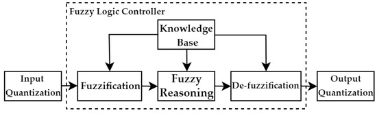
Figure 4.
A block diagram of the principle of the fuzzy control.
The knowledge base of the fuzzy control is generally composed of the database and rule base. The database is a space that stores the membership vector values of all fuzzy sets. The membership vector values of continuous data universe can be expressed by the membership function. The rule base is established on the basis of expert knowledge or long-term operational experience in the research field [28]. All input variables of the system must be fuzzified. The fuzzification mainly includes the determination of fuzzy segmentation and membership function. Fuzzy segmentation refers to the determination of the number of fuzzy sets. Fuzzy reasoning is the key link to get the fuzzy control quantity from the fuzzy input of the controller through the fuzzy rules. The reasoning result of the fuzzy logic is the fuzzy value, which can not be directly output as the control quantity. It needs to be converted into the exact value of the control quantity of the controlled object. This process is the de-fuzzification process of the fuzzy control.
In the case of unknown line resistance, an improved droop controller based on fuzzy logic algorithm is proposed in this paper. By detecting the voltage and power difference of the converter, the droop coefficient is adjusted in real time to reduce the influence of the line resistance on the current sharing accuracy. The fuzzy logic controller is designed as shown in Figure 5, Ui is the ith line port voltage value, ΔPi is the power difference of ith line. Ui and ΔPi are input variables of the fuzzy logic controller, output ri generates the adjustment of the resistance droop coefficient through an integral operation, i.e., ΔRdi. The adjusted droop coefficient Rdi’ is added to the droop control to improve the droop curve.
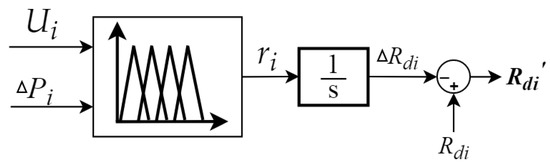
Figure 5.
The fuzzy logic controller.
Where, ΔPi is obtained by comparing the average power of the system with its own power, the calculation formula is shown as follows:
The analysis results are found in Section 2.2, the change of the droop coefficient will cause the bus voltage deviation. The purpose of introducing the voltage amount in the fuzzy logic controller is to prevent the voltage drop from being aggravated by the too large resistive droop coefficient. The fuzzy logic output ri is used as the adjustment of the droop coefficient after integral calculation.
3.1.2. Determination of Fuzzy Logic Rules
In this paper, the reference value of the DC microgrid bus voltage is set to 400 V, and the fluctuation range of Ui is set within ±5% (380 V–420 V). The range of the unbalanced power ΔPi needs to be determined according to the maximum load power value of the system, set ΔPi ϵ (−5, 5) kW. The fuzzy logic output ri is generally smaller than the droop coefficient, generally set ri ϵ (−0.1, 0.1) [29]. In this paper, the triangular membership function is used, the triangular membership function is the most common and simplest fuzzy membership function [30]. The membership functions of the input and output of the controller are shown in Figure 6.
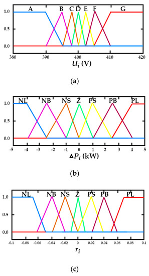
Figure 6.
The membership function. (a) Voltage membership function; (b) power difference membership function; (c) output membership function.
Among them, Ui contains the fuzzy subset A–G range from small to large, ΔPi and ri contain NL, NB, NS, Z, PS, PB, PL, a total of seven fuzzy subsets. Fuzzy rules are established by the logical relation between output and input. With the increase of the resistance droop coefficient, the current sharing accuracy among converters can be improved, but at the same time, the DC bus voltage deviation increases. Therefore, the fuzzy logic rules need to satisfy the following three conditions: When ΔPi (ΔPi > 0 kW) or Ui (Ui > 400 V) is the bigger, the droop resistance needs to be increased; when ΔPi (ΔPi < 0 kW) or Ui (Ui < 400 V) is the smaller, the droop resistance needs to be decreased. When the DC bus voltage is about 400 V and the unbalanced power approaches zero, the droop resistance will not change [29]. According to the above fuzzy logic, the fuzzy logic rule table is established as shown in Table 1, and the reasoning result of the fuzzy logic is shown in Figure 7. The fuzzy rules in Table 1 fully reflect the logical relationship between ri and Ui, ΔPi. The following two rules are selected from the table for illustration:

Table 1.
Fuzzy logic rules.
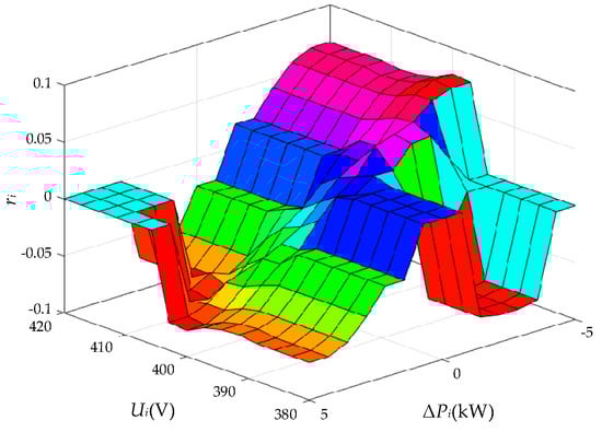
Figure 7.
Fuzzy logic reasoning results.
Rule 1: If Ui is B and ΔPi is NB, then ri is PL.
Rule 2: If Ui is F and ΔPi is PB, then ri is NL.
Rule 1 is interpreted as: When the converter voltage Ui is B and the power difference ΔPi is NB, the output ri given by the fuzzy controller is PL, and the adjusted droop coefficient will reduce to increase the bus voltage.
Rule 2 is interpreted as: When the converter voltage Ui is F and the power difference ΔPi is PB, the output ri given by the fuzzy controller is NL, and the adjusted droop coefficient will increase to reduce the bus voltage.
3.2. The Improved Hierarchical Control Algorithm
The traditional double compensation hierarchical control algorithm based on the voltage and current deviation is shown in Figure 8.
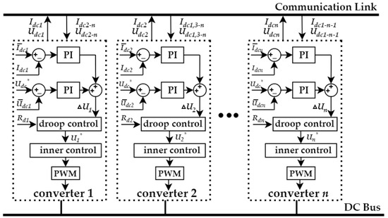
Figure 8.
The traditional double compensation hierarchical control algorithm based on the voltage and current deviation. PI: Proportion-integral.
After collecting the voltage and current information of each DG, calculating the average voltage and current, the deviation of the voltage and current in the local controller is calculated by comparing them, and then the deviation of voltage and current are inputted to the corresponding proportion-integral (PI) controller, respectively. The PI controller of the voltage and current, respectively aims to regulate the DC bus voltage and output current of each converter. The sum of the two regulators is used as the reference voltage value of the local droop control, and the modulation signal of the local converter is generated by the bottom droop control [31]. According to Figure 8, the reference voltage value generated by the ith converter after the secondary control and droop control is shown as follows:
where, Udc* is the initial reference value of the DC bus voltage, Rdi and Idci are the droop coefficient and output current of the ith converter, kpv and kiv are the proportional and integral coefficients of the voltage regulator in the secondary control, and kpc and kic are the proportional and integral coefficients of the current regulator in the secondary control. and are the average voltage and average current of the system, respectively. Ui* is added to the voltage and current double loop control to generate the pulse width modulation (PWM) signal of converter.
The adjusting effect of the control algorithm is shown in Figure 9 [31].
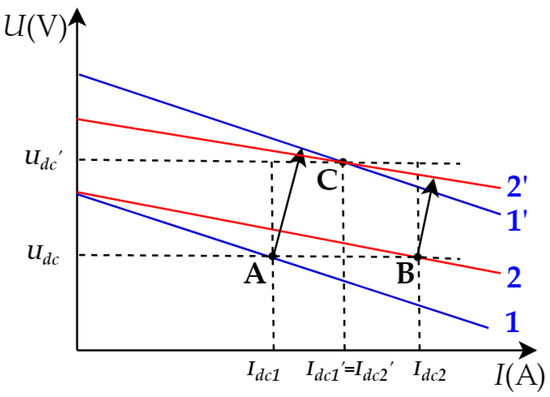
Figure 9.
The adjustment effect diagram of the traditional double compensation secondary control algorithm.
Assuming that in the initial state, converters 1 and 2 operate at points A and B respectively, their output currents are not equal. Under the double compensation hierarchical control algorithm based on the voltage and current deviation, the output voltage and output current are adjusted by adding a compensation term in the droop control, and the intersection point is generated by translating the droop curve, so that the output current of each converter is equal. At this time, converters 1 and 2 work at point C. However, this algorithm does not change the slope of the droop curve, that is, the droop coefficient remains unchanged during the adjustment process. At this time, if the line resistance is different, that is, the external characteristic resistance of the converter is different, when the load power suddenly changes, the dynamic current sharing accuracy of the system will decrease [32].
Therefore, based on the fuzzy logic controller, a droop coefficient regulator is added to exchange the droop coefficient of each converter through the low-speed communication network and calculate its average value, so as to adjust the droop coefficient of each converter. The improved hierarchical control algorithm is shown in Figure 10.
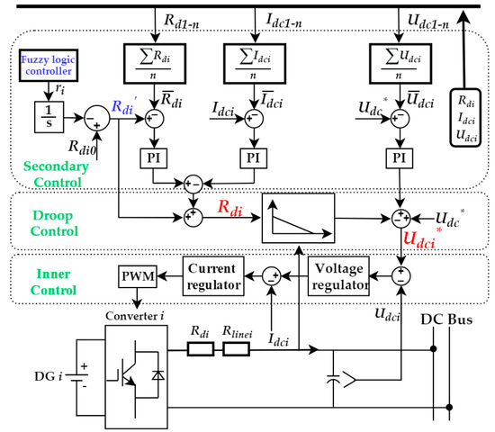
Figure 10.
The structural diagram of the improved hierarchical control algorithm.
The proposed algorithm uses a low-speed communication system of the distributed hierarchical control to obtain the voltage, current and droop coefficients of each unit in the system [26]. Here, only the influence of the secondary and droop control on the control system is considered, and the influence of the parameters of the voltage and current loop in the inner loop control link on the system will be analyzed in detail in the next section. The voltage regulator adopts the voltage feed-forward control [32], which is shown in Figure 11.
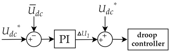
Figure 11.
The voltage feed-forward control.
In the secondary control, the feed-forward compensation control is added to reduce the voltage fluctuation. The current regulator adopts the average current control [13], and takes the average current as a given value to compare with the output current of the converter, the output of the closed-loop regulator and the output value of the droop coefficient regulator are superimposed to participate in the adjustment of the droop coefficient. The voltage regulator generates compensation for the longitudinal intercept of the droop curve, thereby translating the droop curve. At the same time, the droop coefficient regulator and current regulator produce slope compensation of the droop curve. At this time, the external characteristic resistances of parallel converters are equal [33]. Therefore, this algorithm can reduce the bus voltage fluctuation and improve the current sharing accuracy of the system.
The regulation method of the droop coefficient is shown as follows:
where, Rdi’ is the droop coefficient adjusted by the fuzzy logic controller, is the average droop coefficient of all converters in the system, kpd, kid and kpc, kic are the proportional and integral parameters of the droop coefficient regulator and current regulator in the secondary control, respectively.
Under the action of the improved secondary and droop control, the input Udci* of the inner control can be expressed as follows:
where, kpv and kiv are the proportional and integral coefficients of the voltage regulator respectively. Udci* is added to the voltage and current double loop control to generate the PWM signal of the converter.
3.3. Modeling and Analysis of Improved Hierarchical Control Algorithm
Taking two converters with the same capacity as an example, the diagram of the DC microgrid is shown in Figure 12.
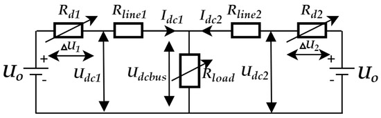
Figure 12.
The diagram of DC microgrid.
Where, Rd1 and Rd2 are the equivalent virtual resistances with an adjustable droop coefficient, which are jointly realized by the current regulator and droop coefficient regulator. The following relation can be obtained from Figure 12:
When the external characteristic resistances of the parallel converters are equal, there are the following relations:
Therefore, under the joint action of the voltage regulator, the current regulator and the droop coefficient regulator, the external characteristic resistances of all parallel converters tend to be the same, which improve the current sharing accuracy [33].
4. Simulation Analysis
4.1. Design of Control System Parameters
The design of the control system parameters is shown in Table 2.
Table 2.
Parameters of the control system.
The line resistance of DG1 is set to 0.3 Ω. Three cases are considered in this paper. The first case is that Rline2 and Rline1 are equal, the second case is that Rline2 and Rline1 are unequal, and the third case is that the difference of Rline2 and Rline1 is large, so set Rline2 = 0.3 Ω, 0.4 Ω, 0.6 Ω, respectively. In order to test the dynamic adjustment ability of the proposed algorithm to the bus voltage and current sharing accuracy, when t = 0.5 s, the load changes from 200 Ω to 100 Ω, and when t = 1 s, the load changes from 100 Ω to 150 Ω.
The bandwidth of the current loop is set to 200 Hz, and the parameters of the current loop are set as: kpc’=0.2, kic’ =4. The bandwidth of the voltage loop should be much smaller than that of the current loop, generally between 10 and 60 Hz [34]. When kpv’ = 2, 4, 6 and kiv’ = 62.8, 125.6, 188.4, the corresponding bandwidth is 13.3 Hz, 32.2 Hz, 42.7 Hz, respectively. The bode diagram and Nyquist curve of the output voltage to the reference voltage are shown in Figure 13.
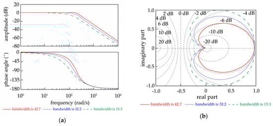
Figure 13.
Parameters design of the voltage loop. (a) The bode diagram of the voltage loop; (b) the Nyquist curve of the voltage loop.
It can be seen from the above figure that, in the low frequency band, the voltage loop has a good tracking ability. The larger the bandwidth of the voltage loop is, the faster the regulation speed will be, but at the same time, the ability to suppress high-frequency signals becomes weaker, and the greater the bandwidth is, the farther it is from the forbidden zone [35]. Therefore, the bandwidth of the voltage loop is set to 13.3 Hz, kpv’ = 2, and kiv’ = 62.8 in this paper.
4.2. Simulation Results and Analysis
Case 1: Setting the line resistance of DG1 and DG2 to be the same, Rline1 = Rline2 = 0.3 Ω. Verifying the control performance of the traditional algorithm and the proposed algorithm to the current sharing accuracy and voltage regulation when the influence of the line resistance is ignored. Figure 14 is the contrast figure of the two algorithms.
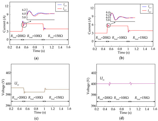
Figure 14.
Simulation results of Case 1. (a) The current distribution under the traditional algorithm; (b) the current distribution under the proposed algorithm; (c) the bus voltage under the traditional algorithm; (d) the bus voltage under the proposed algorithm.
Case 2: Setting different line resistances of DG1 and DG2, Rline1 = 0.3 Ω, Rline2 = 0.4 Ω. Verifying the control performance of the traditional algorithm and the proposed algorithm to the current sharing accuracy and voltage regulation in the case of considering different line resistances. Figure 15 is the contrast figure of the two algorithms.
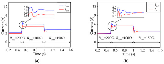
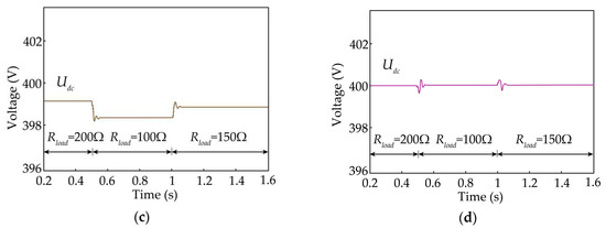
Figure 15.
Simulation results of Case 2. (a) The current distribution under the traditional algorithm; (b) the current distribution under the proposed algorithm; (c) the bus voltage under the traditional algorithm; (d) the bus voltage under the proposed algorithm.
Case 3: Setting different line resistances of DG1 and DG2, Rline1 = 0.3 Ω, Rline2 = 0.6 Ω. Verifying the control performance of the traditional algorithm and the proposed algorithm to the current sharing accuracy and voltage regulation when the difference of the line resistances is large. Figure 16 is the contrast figure of the two algorithms.
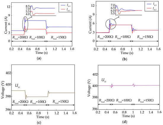
Figure 16.
Simulation results of Case 3. (a) The current distribution under the traditional algorithm; (b) the current distribution under the proposed algorithm; (c) the bus voltage under the traditional algorithm; (d) the bus voltage under the proposed algorithm.
Figure 14 showed that under the condition of the line resistance matching, both the traditional algorithm and the proposed algorithm could reasonably distribute the output current of DG under the condition of load change. Since the traditional algorithm did not compensate the droop resistance, the DC bus voltage could not be maintained on the reference value. As can be seen from Figure 15, in the case of the line resistance mismatch, the current sharing accuracy of the traditional algorithm was obviously reduced. The larger the current required by the load, the greater the error of the current distribution. The proposed algorithm could output the corresponding virtual compensating resistance through the fuzzy logic controller to avoid the decreasing trend of the current sharing accuracy. As can be seen from Figure 16, when the line resistance was seriously mismatched, the current sharing accuracy of the traditional algorithm decreases sharply. The proposed algorithm could still achieve better current sharing accuracy.
5. Conclusions
In this paper, firstly, the principle and limitation of the DC droop control were briefly analyzed. In the case of the large difference in the line resistance, the increase of the droop coefficient could improve the current sharing accuracy of the system, but the too large droop coefficient would aggravate the bus voltage drop, which meant that the voltage regulation and current sharing between DGs could not be realized simultaneously. Then, a fuzzy logic controller was designed, and a hierarchical control algorithm based on improving the droop control was proposed. The algorithm changed the droop resistance by outputting the virtual compensation resistance of the fuzzy logic controller. The droop coefficient regulator and the current regulator together produced the compensation of the slope of the droop curve, and the voltage regulator generated the compensation of the longitudinal intercept of the droop curve. Thus, the droop curve was improved, the current sharing accuracy and voltage regulating ability of the system were improved, and the contradiction between the voltage regulation and current sharing was solved. The proposed algorithm used a low-speed communication system of distributed hierarchical control to obtain the voltage, current and droop coefficients of each unit in the system. The centralized control had obvious defects of a single point fault and no support for plug-and-play. The redundant communication system was needed to reduce the probability of failure, but it increased the cost of the DC microgrid and the complexity of the control system. The tertiary level of control improved the economic benefit and energy efficiency of the microgrid system, but there were still limitations such as control complexity, communication delay and measurement error, and the communication safety factor needed to be optimized and improved. The low-speed communication system of the distributed secondary control reduced the cost of the communication system, solved the drawbacks of the centralized communication system and simplified the structure of the system. The proposed algorithm improved the autonomy, anti-interference ability and stability of the system. Compared with the traditional hierarchical control algorithm, the simulation results verified the effectiveness of the proposed algorithm.
Author Contributions
Project administration, L.Z.; Validation, G.C.; Visualization, S.C. and L.L.; Writing—original draft, K.C.; Writing—review and editing, L.Z.
Funding
This research was funded by the National Natural Science Foundation of China, grant number 51607031 and the Science and Technology Research Project of the 13th five-year Plan of Jilin Provincial Education Department, grant number JJKH20180421KJ.
Conflicts of Interest
The authors declare no conflict of interest.
Abbreviations
| DC | direct current | |
| DG | distributed generation | |
| SOC | state of charge | |
| Udc/Idc | bus voltage/current | V/A |
| Udc*/Idc* | reference bus voltage/current | V/A |
| U0 | open circuit voltage | V |
| Rd | droop resistance (droop gain) | Ω |
| PCC | point of common coupling | |
| Rline | line resistance | Ω |
| ΔUi | voltage drop through the droop resistance | V |
| Idcf | full load current | A |
| ΔPi | power difference | kW |
| ΔRdi | adjustment of the droop coefficient | Ω |
| Rload | load resistance | Ω |
| // | average voltage/current/droop resistance | V/A/Ω |
| PI | proportion-integral | |
| kpv/kiv | proportional and integral coefficients of voltage regulator | |
| kpc/kic | proportional and integral coefficients of current regulator | |
| kpd/kid | proportional and integral coefficients of droop coefficient regulator | |
| PWM | pulse width modulation |
References
- Mi, Y.; Wu, Y.W.; Zhu, Y.Z.; Fu, Y.; Wang, C.S. Coordinated Control for Autonomous DC Microgrid with Dynamic Load Power Sharing. Power Syst. Technol. 2017, 41, 440–447. [Google Scholar]
- Yang, J.; Jin, X.M.; Yang, X.L.; Wu, X.Z. Overview on power control technologies in hybrid AC-DC microgrid. Power Syst. Technol. 2017, 41, 29–39. [Google Scholar]
- Nasirian, V.; Davoudi, A.; Lewis, F.L.; Guerrero, J.M. Distributed Adaptive Droop Control for DC Distribution Systems. IEEE Trans. Energy Convers. 2014, 29, 944–956. [Google Scholar] [CrossRef]
- Tahim, A.P.N.; Pagano, D.J.; Lenz, E.; Stramosk, V. Modeling and Stability Analysis of Islanded DC Microgrids Under Droop Control. IEEE Trans. Power Electron. 2015, 30, 4597–4607. [Google Scholar] [CrossRef]
- Zhu, S.S.; Wang, F.; Guo, H.; Wang, Q.F.; Gao, Y.X. Overview of Droop Control in DC Microgrid. Proc. CSEE 2018, 38, 72–84. [Google Scholar]
- Du, W.J.; Zhang, J.M.; Zhang, Y.; Qian, Z.M. Stability Criterion for Cascaded System with Constant Power Load. IEEE Trans. Power Electron. 2013, 28, 1843–1851. [Google Scholar] [CrossRef]
- Wang, Y.; Zhang, L.R.; Li, H.M.; Liu, J.P. Hierarchical coordinated control of wind turbine-based DC microgrid. Proc. CSEE 2013, 33, 16–24. [Google Scholar]
- Liu, J.Y.; Han, X.Q.; Wang, L.; Zhang, P.; Wang, J. Operation and Control Strategy of DC Microgrid. Power Syst. Technol. 2014, 38, 886–896. [Google Scholar]
- Guerrero, J.M.; Vasquez, J.C.; Matas, J.; Vicuna, L.G.; Castilla, M. Hierarchical Control of Droop-Controlled AC and DC Microgrids-A General Approach Toward Standardization. IEEE Trans. Ind. Electron. 2011, 58, 158–172. [Google Scholar] [CrossRef]
- Xu, Q.W.; Xiao, J.F.; Hu, X.L.; Wang, P.; Lee, M.Y. A Decentralized Power Management Strategy for Hybrid Energy Storage System with Autonomous Bus Voltage Restoration and State-of-Charge Recovery. IEEE Trans. Ind. Electron. 2017, 64, 7098–7108. [Google Scholar] [CrossRef]
- Xu, Q.W.; Hu, X.L.; Wang, P.; Xiao, J.F.; Tu, P.F.; Wen, C.Y.; Yeong, M. A Decentralized Dynamic Power Sharing Strategy for Hybrid Energy Storage System in Autonomous DC Microgrid. IEEE Trans. Ind. Electron. 2017, 64, 5930–5941. [Google Scholar] [CrossRef]
- Dragičević, T.; Guerrero, J.M.; Vasquez, J.C.; Škrlec, D. Supervisory Control of an Adaptive-Droop Regulated DC Microgrid with Battery Management Capability. IEEE Trans. Power Electron. 2014, 29, 695–706. [Google Scholar] [CrossRef]
- Anand, S.; Fernandes, B.G.; Guerrero, J. Distributed control to ensure proportional load sharing and improve voltage regulation in low-voltage DC microgrids. IEEE Trans. Power Electron. 2013, 28, 1900–1913. [Google Scholar] [CrossRef]
- LÜ, Z.Y.; Wu, Z.J.; Dou, X.B.; Hu, M.Q.; Zhao, B. An Adaptive Droop Control for the Islanded DC Microgrid Based on Discrete Consensus Algorithm. Proc. CSEE 2015, 35, 4397–4407. [Google Scholar]
- Xie, W.Q.; Han, M.X.; Wang, H.J.; Li, R.; Wu, M. Multi-source coordinated control strategy of DC micro-grid based on virtual voltage. Proc. CSEE 2018, 38, 1408–1418. [Google Scholar]
- Ding, L.; Han, Q.L.; Wang, L.Y.; Sindi, E. Distributed Cooperative Optimal Control of DC Microgrids with Communication Delays. IEEE Trans. Ind. Inform. 2018, 14, 3924–3935. [Google Scholar] [CrossRef]
- Hu, J.; Duan, J.; Ma, H.; Chow, M.Y. Distributed Adaptive Droop Control for Optimal Power Dispatch in DC Microgrid. IEEE Trans. Ind. Electron. 2018, 65, 778–789. [Google Scholar] [CrossRef]
- Wang, H.J.; Han, M.X.; Guerrero, J.M.; Vasquez, J.C.; Teshager, B.G. Distributed secondary and tertiary controls for I-V droop-controlled-paralleled DC-DC converters. IET Gener. Transm. Distrib. 2018, 12, 1538–1546. [Google Scholar] [CrossRef]
- Lu, X.N.; Sun, K.; Huang, L.P.; Xiao, X.; Guerrero, J.M. Dynamic Load Power Sharing Method with Elimination of Bus Voltage Deviation for Energy Storage Systems in DC Micro-grids. Proc. CSEE 2013, 33, 37–46. [Google Scholar]
- Du, W.J.; Fu, Q.; Wang, H.F. Comparing AC Dynamic Transients Propagated Through VSC HVDC Connection with Master-Slave Control Versus DC Voltage Droop Control. IEEE Trans. Sustain. Energy 2018, 9, 1285–1297. [Google Scholar] [CrossRef]
- Shi, M.X.; Chen, X.; Zhou, J.Y.; Chen, Y.; Wen, J.Y.; He, H.B. Advanced Secondary Voltage Recovery Control for Multiple HESSs in a Droop-Controlled DC Microgrid. IEEE Trans. Smart Grid 2019, 10, 3828–3839. [Google Scholar] [CrossRef]
- He, J.W.; Pan, Y.W.; Liang, B.H.; Wang, C.S. A Simple Decentralized Islanding Microgrid Power Sharing Method Without Using Droop Control. IEEE Tran. Smart Grid 2018, 9, 6128–6139. [Google Scholar] [CrossRef]
- Aderibole, A.; Zeineldin, H.H.; Al Hosani, M.; El-Saadany, E.F. Demand Side Management Strategy for Droop-Based Autonomous Microgrids Through Voltage Reduction. IEEE Trans. Energy Convers. 2019, 34, 878–888. [Google Scholar] [CrossRef]
- Yang, J.; Jin, X.M.; Wu, X.Z.; Jiang, C. An Improved Load Current Sharing Control Method in DC Microgrids. Proc. CSEE 2016, 36, 59–67. [Google Scholar]
- Khorsandi, A.; Ashourloo, M.; Mokhtari, H. A decentralized control method for a low-voltage DC microgrid. IEEE Trans. Energy Convers. 2014, 29, 793–801. [Google Scholar] [CrossRef]
- Lu, X.N.; Guerrero, J.M.; Sun, K.; Vasquez, J.C. An Improved Droop Control Method for DC Microgrids Based on Low Bandwidth Communication with DC Bus Voltage Restoration and Enhanced Current Sharing Accuracy. IEEE Trans. Power Electron. 2014, 29, 1800–1812. [Google Scholar] [CrossRef]
- Zhang, K.; Wu, J.D.; Mao, C.X.; Lu, J.M.; Wang, D.; Huang, H. Optimal Control of Energy Storage System for Wind Power Generation Based on Fuzzy Algorithm. Trans. China Electrotech. Soc. 2012, 27, 235–241. [Google Scholar]
- Ahmadi, S.; Shokoohi, S.; Bevrani, H. A fuzzy logic-based droop control for simultaneous voltage and frequency regulation in an AC microgrid. Electr. Power Energy Syst. 2015, 64, 148–155. [Google Scholar] [CrossRef]
- Yan, L.F.; Liu, J.; Shi, M.X.; Chen, X.; Wen, J.Y. Adaptive Power Allocation Strategy Based on Fuzzy Logic Algorithm for Hybrid Energy Storage System in DC Microgrid. Proc. CSEE 2019, 39, 2658–2669. [Google Scholar]
- Yu, X.W.; She, X.; Ni, X.J.; Huang, A.Q. System Integration and Hierarchical Power Management Strategy for a Solid-State Transformer Interfaced Microgrid System. IEEE Trans. Power Electron. 2014, 29, 4414–4425. [Google Scholar] [CrossRef]
- Guo, Q.L.; Fan, S.; Zhou, C.Y.; Wang, H.; Wang, X.J. Research on Control Strategy of Smooth Switching Between Microgrid and Distribution Network Based on Fuzzy Principle. High Volt. Eng. 2015, 41, 3281–3287. [Google Scholar]
- Li, X.L.; Wang, C.S.; Guo, L.; Zhou, L.H.; Feng, T.B. Key technologies of DC microgrids: An overview. Proc. CSEE 2016, 36, 2–17. [Google Scholar]
- Mi, Y.; Wu, Y.W.; Fu, Y.; Wang, C.S. Hierarchical coordinated control of island DC microgrid with photovoltaic and storage system. Power Syst. Prot. Control 2017, 45, 37–45. [Google Scholar]
- Wang, P.B.; Lu, X.N.; Yang, X.; Wang, W.; Xu, D.G. An Improved Distributed Secondary Control Method for DC Microgrids with Enhanced Dynamic Current Sharing Performance. IEEE Trans. Power Electron. 2016, 31, 6658–6673. [Google Scholar] [CrossRef]
- Zhi, N.; Zhang, H.; Xiao, X. Research on Improved Drop Control Strategy for Improving Dynamic Characteristics of DC Microgrid. Trans. China Electrotech. Soc. 2016, 31, 31–39. [Google Scholar]


© 2019 by the authors. Licensee MDPI, Basel, Switzerland. This article is an open access article distributed under the terms and conditions of the Creative Commons Attribution (CC BY) license (http://creativecommons.org/licenses/by/4.0/).