Article

Numerical Investigations of a Tip Turbine Aerodynamic Design in a Propulsion System for VTOL Vehicles

College of Energy and Power, Nanjing University of Aeronautics and Astronautics, Nanjing 210016, China
*
Author to whom correspondence should be addressed.
Energies 2019, 12(15), 3003; https://doi.org/10.3390/en12153003
Submission received: 1 July 2019 / Revised: 25 July 2019 / Accepted: 31 July 2019 / Published: 3 August 2019

Abstract

:
High thrust and low specific fuel consumption (SFC) are important for vertical takeoff and landing (VTOL) vehicles. An effective way to decrease the SFC is to increase the bypass ratio (BPR) of the propulsion system. The air-driven fan (or fan-in-wing) has a very high bypass ratio and has proved to be successful in VTOL aircrafts. However, the tip turbine that extracts energy for the air-driven fan faces the low-solidity problem and performs inadequately. In this study, we developed a high-reaction method for the aerodynamic design of a tip turbine to solve the low-solidity problem. A typical tip turbine was selected and designed by both conventional and high-reaction methods. Three-dimensional flow fields were numerically simulated through a Reynolds-averaged Navier-Stokes (RANS)-based computational fluid dynamics (CFD) method. The energy extraction rate was proposed to evaluate and display the energy extraction capability of the turbine. The results showed that the high-reaction turbine could solve the low-solidity problem and significantly increase the isentropic efficiency from approximately 80.0% to 85.6% and improve the isentropic work by 71.9% compared with the conventional method (from 10.28 kW/kg to 17.67 kW/kg).

1. Introduction

The aircraft vertical takeoff and landing (VTOL) capability has become an important field in current aviation technology research. The U.S. Army has listed the VTOL aircraft as the first of its 10 key future development projects [1,2]. The propulsion systems for VTOL vehicles have two requirements: low specific fuel consumption (SFC) during takeoff and landing procedures and a multipoint distributed arrangement. The air-driven fan (as well as the lift fan) has proved to be very effective at achieving vertical takeoff and landing. For example, Przedpelski [3] studied the XV-5 using lift fan in the early 1960s, and Hunziker [4] summarized the research work of X-32 of the Boeing Company, which also applied a lift fan in the 2000s. For VTOL aircraft, Zimbrich concluded in reference [5] that the bypass ratio (BPR) of its engine must be high under takeoff conditions to ensure the thrust against its weight. In Kutney’s research [6], it was demonstrated that such tip turbine cruise and lift fans can reach a BPR range of 10–50. The tip turbine is one of the key components of this kind of propulsion system and is mounted at the tip of a fan. The air that drives the fan comes from the core turbo engine and is piped into tip turbines distributed across multiple positions of the aircraft. As an important energy supply component, a tip turbine with good aerodynamic performance will guarantee a high-efficiency propulsion system.
Research on tip turbines has continued over the past decades. Studies have mainly focused on the performance potential of a lift-fan with a tip turbine. Ronald [7] summarized the tip turbine lift-fan aircraft, showing that it has certain advantages in its engineering applications, transmission weight, and maintenance. Asmus [8] summarized the design and development of the lift fan with tip turbines, including its structure, performance, and engineering progress. In his research, several kinds of lift fan structure (as well as tip turbine) are mentioned, but all the tip turbines are designed with a conventional method. In 2013, Anthony [9] provided a detailed summary of the development and application of lift-fan technology from the age of the XV-5A to the 1990s, and concluded that this kind of lift fan with tip turbines will have potential applications in the future. Their research shows that a lighter system weight is one of the advantages of applying a tip turbine, while a lift fan with a tip turbine is suitable for VTOLs. As VTOL unmanned aerial vehicles (UAVs) have become popular, many researchers have proposed the use of tip turbines in the propulsion system of small- and medium-sized UAVs. Nobuhiro [10] proposed the Air Turbo Ramjet of EXpander cycle (ATREX) in 1994, which could fly from subsonic to Mach 2. It uses the tip turbine structure to provide compactness and reduce the weight of the turbine. Hatta et al. [11] discussed in detail the structural design of the tip turbine of the ATREX engine, as well as the strength of the turbine. In these research focused on VTOL UAVs, the tip turbines are still designed and constructed in a conventional way.
Besides, few articles mentioned the aerodynamic performance of a tip turbine and a further reduction of the turbine weight. In the 1970s, Haas firstly studied the tip-turbine-driven propulsion fan concept experimentally, including the performance of tip turbines [12,13], and the results showed that the efficiency of the tip turbine was around 86.1%. Bond [14] proposed a CBCC (Collection Based Combined Cycle) engine with tip turbine to propel the vehicle into near-Earth orbit. In his research, a three-stage tip turbine was used to extract energy from hot hydrogen gas, and the isentropic efficiency of this tip turbine was estimated to be only 50%. In 2002, Casado [15] proposed a propulsion fan system driven by a tip turbine and studied the aerodynamic design of the tip turbine with the conventional solidity. However, in the research, it is concluded that an impulse turbine with low solidity could be the optimum configuration in terms of the mechanical integrity. In 2018, Huang [16] mentioned a very low solidity tip turbine in a high-bypass propulsion system using an air-driven fan with a tip turbine (ADFTT). In the research, the performance of a low solidity tip turbine was numerically studied and the results showed that the efficiency of the tip turbine was greater than 85%. However, the design method was only introduced in brief.
With the development of the aerodynamic design technology, the tip turbine is developing towards higher efficiency and lower weight, which are characteristics that require better aerodynamic design and fewer blades. In this study, we developed the high-reaction method for the aerodynamic design of a tip turbine to achieve high efficiency with a limited blade number, and summarized the mechanism of this method to improve the flow field, which is a continuation of the research done on ADFTTs. The tip turbine was used in the air-driven fan propulsion system (Figure 1), which provided the main lift for a conceptual UAV (Figure 2). The tip turbine was designed using both conventional and high-reaction methods. The performances of the tip turbine were numerically simulated using the Shear Stress Transfer (SST) based computational fluid dynamics (CFD) method. The manner in which the design technique improved this low-solidity tip turbine was analyzed in detail. To evaluate and display the energy extraction capability of this turbine, we proposed an appropriate parameter, namely the energy extraction rate.

2. Conventional Design of the Tip Turbine

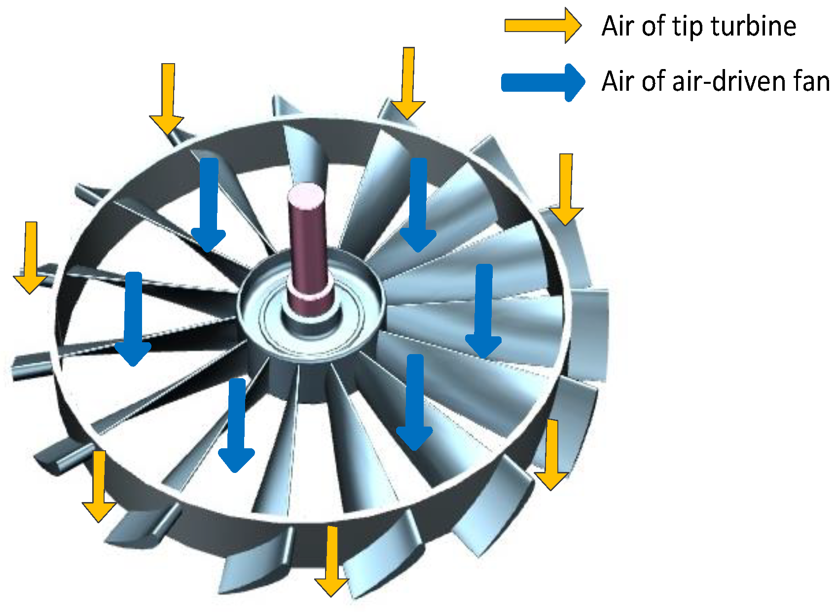
2.1. Structural Characteristics of the ADFTT Rotor

The ADFTT rotor is an aerodynamic component with two parts (Figure 3), namely, the fan and the tip turbine mounted at the tip of the fan. There are several other components to make it work properly: the volute, the stator of ADFTT and the exhaust device (to adjust the vent). The fan and tip turbine are attached to each other in a structural and aerodynamic design. More details about the structural characteristics of ADFTT can be found in reference [16]. The most important characteristic of ADFTT is that the turbine rotor must have the same number of blades as the fan. This number is less than a conventional tip turbine—for example, the tip turbine lift fan in the VX-5 (in reference [9]). On the one hand, reducing the number of the rotor blades could decrease the centrifugal force on the fan blades, thus laying the foundation for further improving the rotation speed of the air-driven fan. On the other hand, using a smaller number of blades could also reduce the weight. So we minimized the number of turbine blade as much as possible: the turbine has the same number of blades as the fan.
Since there are few blades, the solidity of the tip turbine in the ADFTT rotor is very low, which causes the low-solidity problem, which is that the blades are too far apart to form a complete flow path. It is difficult for the blades to restrain the airflow effectively, which leads to severe flow separation. Some air may just leak through the turbine without contributing to driving the fan. Put simply, the limited blade number causes difficulties in the turbine aerodynamic design.

2.2. Performance Estimation of the Tip Turbine

In order to investigate the deterioration of turbine performance caused by the low-solidity problem, we chose a typical tip turbine and designed it with the conventional method and a conventional number of blades. For rapid processing and experimental research, the performance of the tip turbine was estimated according to the gas supply equipment, which was a micro-scale gas turbine engine with an after fan. The total pressure of the gas provided by such equipment was 122,080 Pa, the total temperature was 444 K, and the mass flow rate was 0.56 kg/s. The design parameters of the ADFTT are shown in Table 1. The bypass ratio of this ADFTT, the ratio of mass flow rate of air-driven fan to that of tip turbine, was almost 8.9, and considering the bypass of the after fan, the equivalent bypass ratio could be very high. For example, if the BPR of core engine is 2, then the whole BPR of the propulsion system using such ADFTT could be 17.8. Such a high BPR makes the propulsion system applicable for vertical takeoff and landing situations. More detailed theories about such a propulsion system can be found in reference [16].

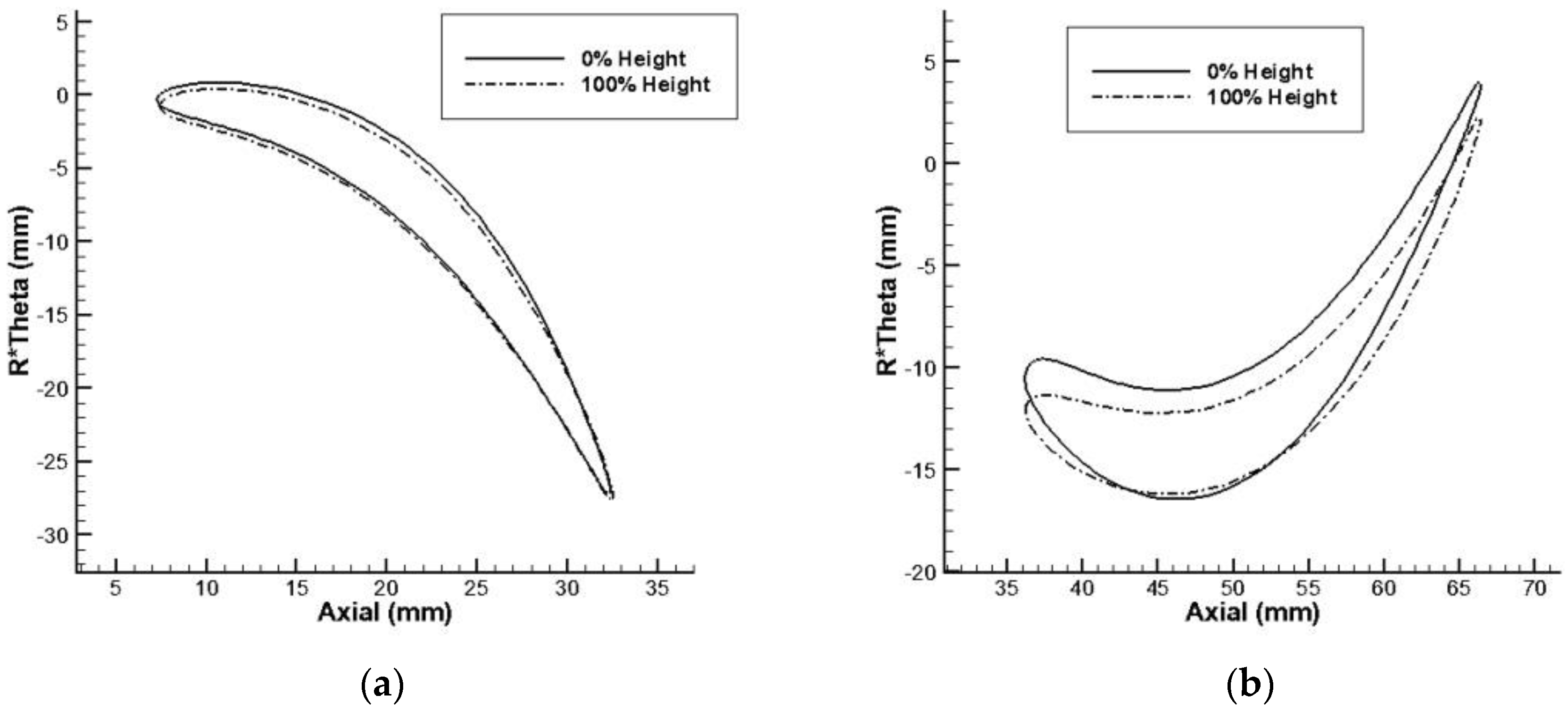
2.3. Profile Design of the Tip Turbine by the Conventional Method

The design processes of the tip turbine are the same as that of other turbo machinery. They include preliminary, through flow, 2D blading, and 3D blading designs [17]. In conventional method, the most important thing is to determine the velocity triangle of the rotor: the values of flow velocities of inlet and outlet are determined, as well as the angles of those velocities. So the main parameters of turbine blades could be determined. The reaction degree ( Ω ) is a parameter for fine-tuning, which is used to adjust the blade parameters (such as the angle of absolute velocity at the outlet of the stator) to ensure the parameters are in an optimal rang. In the actual physical sense, the reaction degree could measure the percentage of gas expansion in the turbine rotor to the total isentropic work of the whole elementary stage. Its formula is as follows:
Ω = w 2 2 w 1 2 2 L u
where w 1 is the relative velocity of the rotor inlet, and w 2 is the relative velocity of the rotor outlet. L u is the isentropic work of the whole elementary stage, and its formula is
L u = c 1 2 c 2 2 2 + w 2 2 w 1 2 2
where c 1 is the absolute velocity of the rotor inlet, the c 2 is the absolute velocity of the rotor outlet.
For a reaction turbine, the reaction degree of the turbine is more than 0; this is widely used in gas turbines due to its positive pressure gradient in the rotor. If the reaction degree is high, it means that the gas expands more in the rotor than in the stator and causes a high positive pressure gradient in the rotor. If the reaction degree is 0, the turbine is called an impulse turbine, which means that the gas expands only in the stator. Usually, the reaction degree of the turbine is between 0.2 and 0.4. High-reaction degree is relative concept, which means the reaction degree of a high-reaction turbine is higher than conventional turbine. A high-reaction turbine has two benefits: one is its positive pressure gradient; the other is the reduction in the deflection angle of flow in the rotor. Both of these benefits make it difficult for airflow to separate. However, in a high-reaction turbine, the relative velocity in the rotor is increased, which also limits the improvement of the rotor’s efficiency and can even cause transonic or supersonic problems. As a result, a high-reaction turbine is not widely used in conventional turbine design. More detailed theories on this can be found in reference [18].
In this study, we first designed a tip turbine using the conventional method: the tip turbine had a conventional blade number and reaction degree. The profiles of the stator and rotor are depicted in Figure 4. All the blades were staked by the center of gravity. The one-dimensional thermodynamic parameters of the conventional tip turbine are shown in Table 2.

3. Numerical Investigations of the Tip Turbine Designed by the Conventional Method

The performance of the tip turbine was numerically evaluated through the CFD method. Considering that the blade number of the tip turbine rotor was very low, the aerodynamic performances of the blades obtained by the conventional method using two different blade numbers were calculated, respectively. The blade number of the rotor was 57 for the conventional-solidity design, so its solidity is 1.7 (For conventional turbine, the solidity is ranged from 1.4 to 1.7). For low-solidity design, the blade number of the rotor was 13, which equaled the blade number of the air-driven fan. The blade number of the stator remained at 47.

3.1. CFD Method

The commercial CFD software Numeca, including the meshing module Autogrid and the computing module Fine, was used for numerical simulation. Steady simulation is used to obtain the flow field. The flow field was calculated using a 3D RANS equation method with a space-central difference scheme and four-step time advancement implemented using the Runge–Kutta method. The turbulence model of shear-stress transport (SST) [19,20] is used in this study because the shear stress and compressibility of fluid can be significant at the interaction region. The SST model is formulated as:
( ρ k ) t + ( ρ u j k ) x j = x j [ ( μ + σ k μ t ) k x j ] + P k β * ρ k ω
( ρ ω ) t + ( ρ u j ω ) x j = x j [ ( μ + σ ω μ t ) ω x j ] + α ρ S 2 β ρ ω 2 + 2 ( 1 F 1 ) ρ σ ω 2 ω k x j ω x j ,
where F 1 is defined by:
F 1 = tanh { [ min ( max ( k 0.09 ω d , 500 μ ρ d 2 ω ) ; 4 ρ σ ω 2 k C D k ω d 2 ) ] 4 } ,
with C D k ω is:
C D k ω = max ( 2 ρ σ ω 2 ω k x j ω x j ; 10 20 ) ,
The μ t is the turbulent eddy viscosity and is defined as:
μ t = min [ ρ k ω , ρ a 1 k Ω F 2 ] ,
where F 2 is defined by:
F 2 = tanh { [ max ( 2 k 0.09 ω d , 500 μ ρ d 2 ω ) ] 2 } ,
All the model parameters are calculated by the equation as:
ϕ = F 1 ϕ 1 + ( 1 F 1 ) ϕ 2
where ϕ represents the parameter in { σ k , σ ω , β , γ }. The model contains 9 specified parameters: { a 1 , k , β * , σ k 1 , σ ω 1 , β 1 , σ k 2 , σ ω 2 , β 2 } and two intermediate parameters { γ 1 , γ 2 } which are calculated by:
γ 1 = β 1 β * σ ω 1 k 2 β *
γ 2 = β 2 β * σ ω 2 k 2 β *
The total 9 specified parameters in this research are used with their nominal values: a 1 = 0.31 , k = 0.41 , β * = 0.09 , σ k 1 = 0.85 , σ ω 1 = 0.5 , β 1 = 0.075 , σ k 2 = 1.0 , σ ω 2 = 0.856 , β 2 = 0.0828 .
An adiabatic and no-slip wall condition was adopted, and a periodic boundary was set for blade passage, thereby ignoring the clearance of a rotor blade. The boundary conditions were set as follows: the total pressure of the inlet of the tip turbine was 122,080 Pa, the total temperature was 444 K, the and static pressure of the outlet was 101,300 Pa; the adiabatic and non-sliding solid wall treatment method was adopted; and the blade surface and hub surface were set as a rotating boundary, the casing was a static boundary, and the blade passage was a periodic boundary. Figure 5 demonstrates the grid of the tip turbine.
Figure 5 shows the grid of tip turbine. All the grids in this study used the same grid generation technology and had the same grid number. The y+ was less than 1 to meet the requirement of SST model.

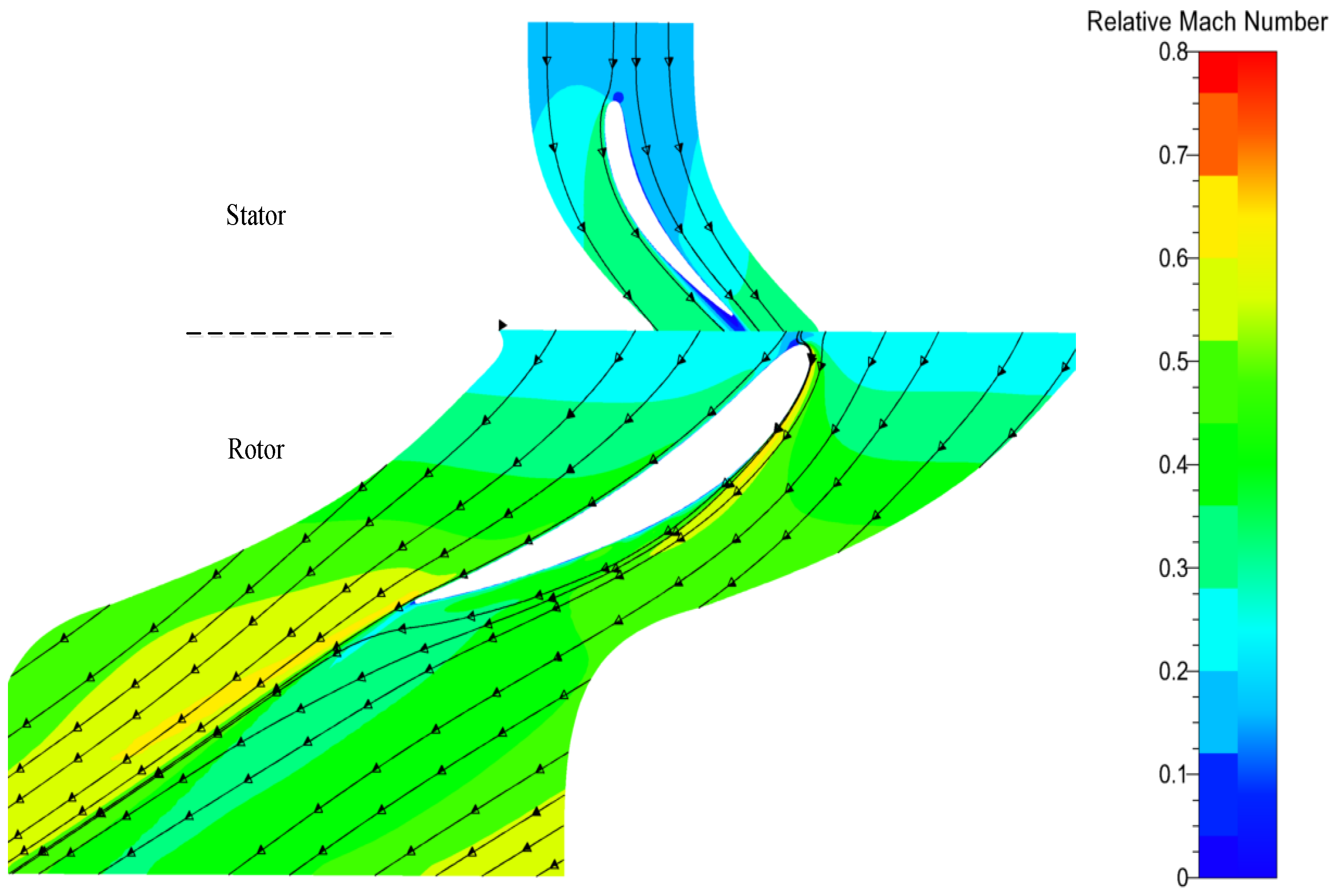
3.2. CFD Results and Flow Field Analysis

In the case of two different numbers of rotor blades, the performance of the turbine varies greatly. Given the blade number limitation in an air-driven fan, the solidity of the tip turbine is too low and cannot establish an integrated flow path by its adjacent blades if the turbine is designed through a conventional design process of turbo machinery. Table 3 shows the performances of the two tip turbines. When the conventional design method was used, the tip turbine performance matched the design requirements with conventional solidity. However, when the solidity was low, not only did the pressure ratio become lower but also the isentropic efficiency. This led to insufficient isentropic work extracted by the tip turbine from the airflow. The CFD results showed that the energy extracted by the low-solidity tip turbine only accounted for 58.5% of the design requirements. In other words, the thrust of the propulsion system will decrease dramatically.
Figure 6 displays the Mach number distributions of the tip turbines with conventional and low solidities. The low solidity turbine has a large area blocked by the separation which blocked a part of the flow path and dramatically reduced the turbine efficiency, while a conventional turbine has no such area. The air acceleration in the middle of the flow path was lower than that near the pressure side. On the one hand, the separation vortices dissipated a considerable amount of energy; on the other hand, they occupied a wild path, which led to the main flow not achieving the designed flow deflection angle. The ultimate result was that the relative deflection angle decreased from 85 degree in the conventional solidity turbine to 41 degree in low solidity turbine, and the ability of the turbine to extract energy was greatly weakened. This was consistent with the simultaneous reductions of efficiency and the pressure ratio.

3.3. Energy Extraction Rate Analysis

To estimate the ability of the turbine to extract energy, the energy extraction rate ξ extract was introduced. Its formula is
ζ extract = ( C ¯ 1 2 C 2 i 2 ) + ( W 2 i 2 W ¯ 1 2 ) 2 L u
where C ¯ 1 is the average absolute velocity of the rotor inlet, C 2 i is the local absolute velocity at the rotor outlet, W 2 i is the local relative velocity at the rotor outlet, and W ¯ 1 is the average relative velocity of the rotor inlet. ξ extract is the ratio of the isentropic work of local flow to the isentropic work of the design requirements. When it is less than 1, this means that the turbine extracts less energy from the local flows; when it is more than 1, this means that the turbine extracts too much energy from the local flows. A well-designed turbine should have a very uniform energy extraction rate distribution, and the energy extraction rate of most regions should be around 1. If the (average) energy extraction of whole flow in turbine is 1.0, it means that the energy extracted from the turbine just meets the needs of the fan.
Figure 7 displays the energy extraction rate distributions of the tip turbines. In the conventional-solidity turbine (Figure 7a), the energy extraction rate was mostly around 1, indicating that it was well designed. Only the area occupied by the wake and tip leakage flow had a very low energy extraction rate.
However, the situation was quite different for the low-solidity turbine (Figure 7b). The area with a high energy extraction rate existed only near the pressure surface. The energy extraction rate in the mainstream region was only approximately 0.4. This indicated that the fluid energy in this region was only partially extracted by the turbine, while the remaining energy was wasted (neither extracted nor dissipated). The wake and tip leakage (as well as the separation flow) occupied the region near the suction surface and reduced the energy extraction rate to about 0.2. In this region, the fluid energy dissipated due to the vortices and interactions. The average energy extraction rate was near 0.5, which matched the isentropic work (the isentropic work of the low-solidity tip turbine was only 58.5% of the design requirement).
In conclusion, the conventional design method could produce a well-designed tip turbine with good performance under a conventional-solidity condition, but it could not be applied under a low-solidity condition. Considering the specific structural and strength requirements of the ADFTT, the aerodynamic design method needs to be improved.

4. Numerical Investigations of the Tip Turbine Designed by the High-Reaction Method

4.1. Principle of the High-Reaction Method

Unlike the conventional design method, the high-reaction design method adopts a high-reaction degree, which reduces the expansion of the flow in the stator, increases the expansion in the rotor, and reduces the deflection angle of the flow in the rotor. By comparing and analyzing the velocity triangles, we can see the difference between the two methods (Figure 8). The deflection angle of flow Δ β in the rotor is much lower than that in the conventional method when the high-reaction method is used. The circumferential speed U remains the same, as well as the absolute velocity difference Δ C u . However, in the high-reaction method, the relative velocity deflection angle Δ β is much smaller. Both w 1 and w 2 are increased and more tangential. Inlet absolute velocity c 1 is decreased, indicating that the flow accelerates less in the stator. Nevertheless, in the ADFTT, the pressure ratio is not high and the relative velocity can be controlled under a subsonic condition. So, the high-reaction method is suitable for tip turbine design.
By using the high-reaction method, we set the reaction degree target at 1.0. Other parameter design methods were the same as those discussed in Section 2.3. The one-dimensional thermodynamic parameters of the designed high-reaction tip turbine are shown in Table 4. The profiles of the stator and rotor are depicted in Figure 9. Compared with the profiles of the conventional method, the deflection angle of the camber of the stator decreased greatly. The angles of the camber of the rotor also changed greatly. The hub diameter was slightly increased to ensure that the relative velocity was not too tangential. Other geometric parameters and the rotational speed were the same as those in Table 2.
In addition, we did not want to limit the value of the reaction degree, which was set to 1 as a relatively high value. At present, the visible limitation of the reaction degree is that when the reaction degree is too high, the relative velocity in the rotor will be too high, resulting in aerodynamic losses (even a shock wave). In this study, when the reaction degree was 1, the problem of excessive relative speed was not obvious.

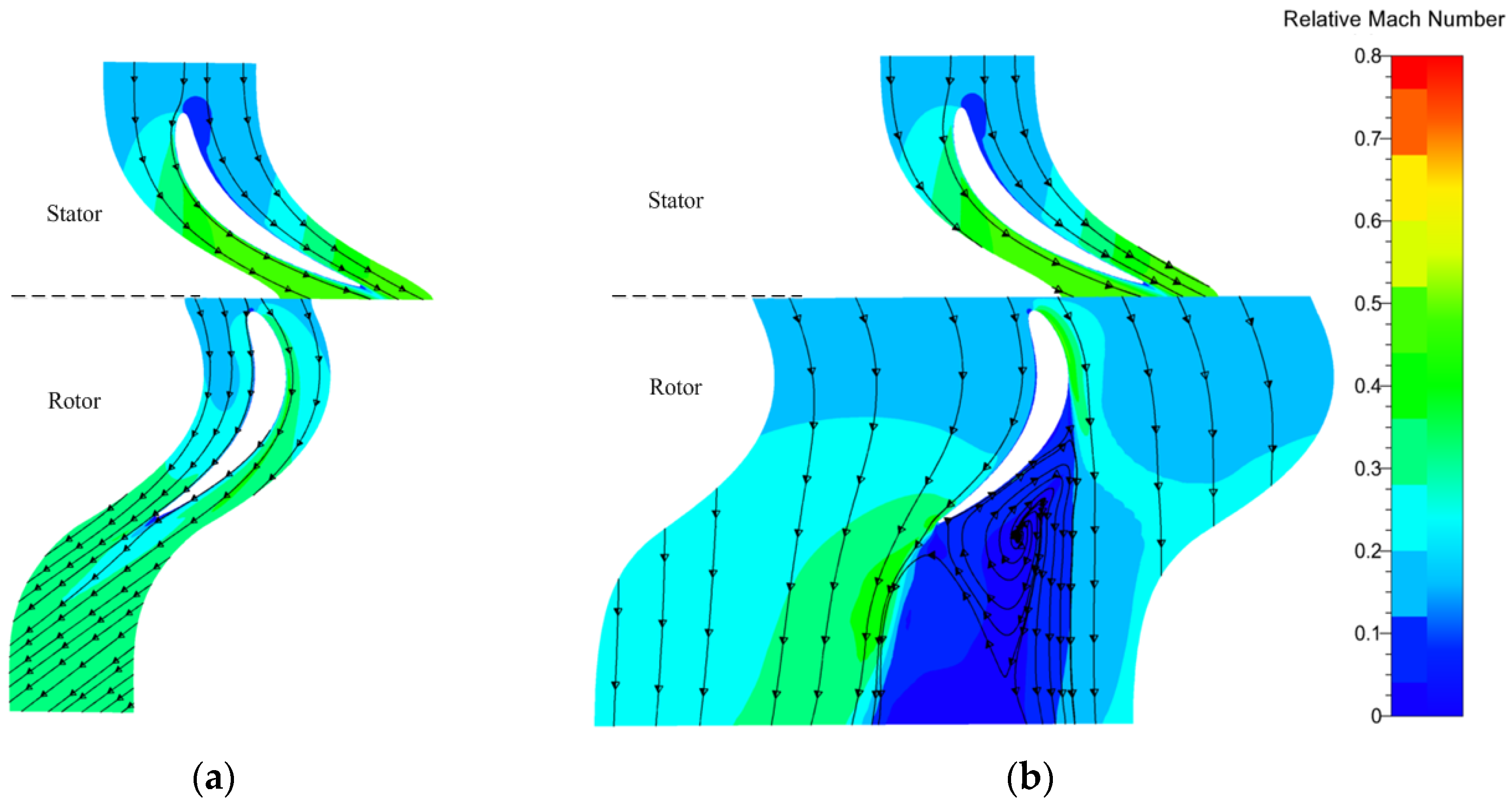
4.2. Flow Field Analysis

The performance of the high-reaction method tip turbine was numerically simulated with the same CFD method as mentioned in Section 3.1. The outlet boundary was slightly decreased from 101,300 to 99,000 Pa due to the reduction of the flow path size, while the others remained the same (The outlet boundary of design point could be slightly adjusted by the adjustable venting nozzle). This change might alter the flow upstream and make it less sensitive to separation. However, it has a small advantage when making the flow less sensitive to separation, compared with the deflection angle change caused by the high-reaction design method.
Figure 10 displays the Mach number distributions of the tip turbines with the high-reaction method. The distributions and stream lines showed that both the stator and the rotor worked well. The Mach number of the stator outlet was around 0.35, less than that of the conventional method design (about 0.45, Figure 6). The relative Mach number of the main flow in the rotor ranged from 0.4 to 0.65. The performance of this high-reaction tip turbine (Table 5) showed that it matched the design requirements. Under low-solidity condition, the isentropic work of tip turbine was improved from 10.28 kW/kg to 17.67 kW/kg by this high-reaction design method. Also the relative deflection angle Δ β was reduced to only 32.4°, which conformed to the velocity triangle analysis.
The details of the flow field show the reason for the high-reaction tip turbine overcoming the difficulties of low solidity. The high-reaction turbine could form an aerodynamic flow path with limited blades and chord length. Figure 11 shows such phenomena, which we named “aerodynamic extending”. It can be seen clearly that the gas traveled through a “Laval tube” enclosed by four borders: A1 at the front, A3 at the rear, the wall boundary, and the shear boundary of the wake. The throat of the tip turbine was located at section A2. With this aerodynamic extending, the turbine could obtain an equivalent flow path to complete the organization of the flow.
Figure 12 shows the static pressure distributions of different sections. Before A1, the static pressure was high, which provided high pressure for the pressure surface of the blade. From A1 to A2, the aerodynamic path was contractive, so the flow was accelerated and the static pressure decreased. The maximum Mach number region appeared near A2, which was the aerodynamic throat. From A2 to A3, the expansion of the flow tube, which could not be avoided due to the integration of the blade, resulted in an increase in the static pressure of the flow. The blade load diagram (Figure 13) also confirms the variation of static pressure. The entire pressure surface was covered by the region before A1 and the static pressure decreased gradually and continuously. Then, from A1 to A2, the static pressure dropped dramatically near the leading edge and reached its lowest value at A2. After A2, the static pressure rose slowly until A3 was reached, which led to airflow deceleration and the risk of flow separation.
Figure 14 shows the profiles of the relative Mach number of two different designed tip turbines at inlet and outlet. They were both low solidity turbines with only 13 rotor blades. In both turbines, the relative Mach number increased from inlet to outlet. However, the relative Mach number in high-reaction turbine was higher than that in conventional turbine both at inlet and outlet. Especially, at the outlet location, the relative Mach number of high-reaction turbine was significantly higher than that of the conventional turbine. This phenomenon proved the analysis of the velocity triangle in Section 4.1.

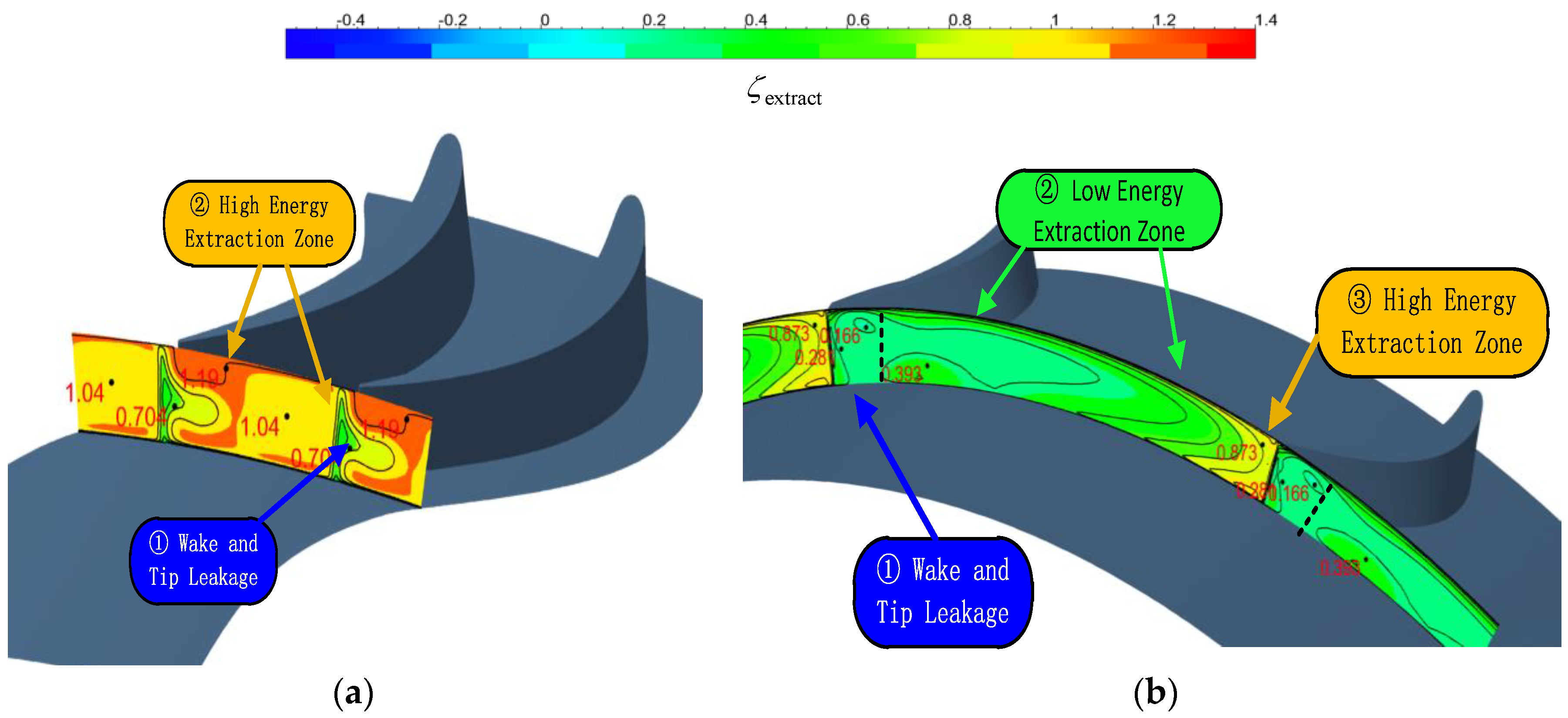
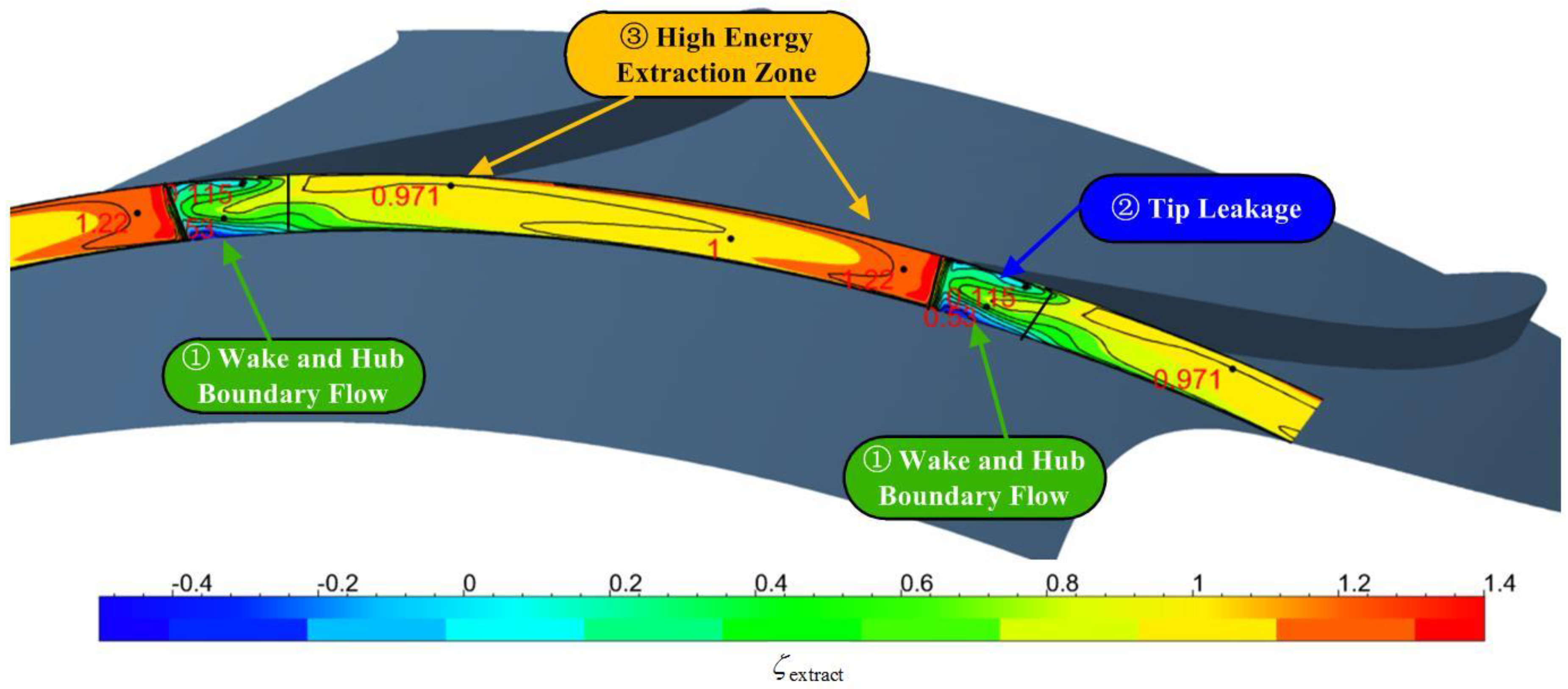
4.3. Energy Extraction Rate Analysis

The energy extraction rate distribution (Figure 15) clearly shows the improvement of the tip turbine’s energy extraction ability. The energy extraction rate of the whole path was more uniform at around 1.0, which indicated that the design was successful. Most parts of the flow path became a high energy extraction zone. Only the region near the trailing edge of the suction surface had a lower energy extraction value because of the tip leakage flow and the wake. The tip leakage flow influenced the flow near the suction surface, occupied the upper part of the path, so the lowest energy extraction value in this area was about 0.4. The energy of the flow in this region was wasted, which could be further improved by leakage-suppression technology. The wake occupied the lower part, and the lowest energy extraction value was about −0.5. The negative value represents that not only that the energy in this region failed to be extracted, but also that more energy transferred from the mainstream region dissipated. Considering the overall situation of the energy extraction rate, the energy extraction of the tip turbine met the design requirements and the efficiency was high, indicating the success of the design method.

5. Conclusions

This research presented numerical investigations of a tip turbine aerodynamic design for a propulsion system for VTOL aircrafts. A high-reaction method was proposed to address the low-solidity problem of the tip turbine. Some details of the tip turbine flow field designed by the conventional and high-reaction methods were compared, including the performance and energy extraction rate. From the work discussed above, the following conclusions can be drawn:
  • Conventional design methods are not suitable for tip turbine designs with low solidity. Under a low-solidity condition, the performance of a tip turbine will be greatly reduced, including the pressure ratio, efficiency, and energy extraction rate, resulting in an inadequate energy extraction capability.
  • The high-reaction method can successfully solve the problems caused by low solidity in a tip turbine. The distribution of the energy extraction rate is more uniform and the value is higher. In this study, compared with the conventional method, the high-reaction method improved the isentropic work by 71.9% under the low-solidity condition (from 10.28 kW/kg to 17.67 kW/kg) and the isentropic efficiency increased from 80.0% to 85.6%, meaning the performance of the tip turbine met the design requirements.
  • The tip turbine designed by the high-reaction method could form a complete flow path in an aerodynamic extending way. A Laval-tube-type flow tube could be found in the rotor flow field, which was formed by the wall boundary of the suction surface and the shear boundary of the wake. Therefore, the rotor could organize the airflow effectively.

Author Contributions

Conceptualization, G.H. and X.X.; methodology, X.X.; validation, X.X.; formal analysis, G.H.; investigation, X.X., W.L., and L.L.; resources, G.H.; data curation, X.X.; writing—original draft preparation, X.X.; writing—review and editing, G.H. and J.C.; visualization, X.X. and G.H.; supervision, G.H.; project administration, G.H.; funding acquisition, G.H.

Funding

This research was funded by the Aviation Power Fund of China (Grant number 6141B090318).

Acknowledgments

The authors express their gratitude to the Jiangsu Province Key Laboratory of Aerospace Power System (affiliated with the College of Energy and Power Engineering, Nanjing University of Aeronautics and Astronautics) for the technical support. The authors are also grateful to the team members of the College of Power and Energy of Nanjing University of Aeronautics and Astronautics for their cooperation.

Conflicts of Interest

The authors declare no conflict of interests.

References

  1. Marin, N.; Spataru, P. The role and importance of UAV within the current theaters of operations. INCAS Bull. 2010, 2, 66–74. [Google Scholar]
  2. Li, N. The US army ten key techniques needed for next warfare. New Time Def. 2011, 12, 1–8. (In Chinese) [Google Scholar]
  3. Przedpelski, Z. Lift Fans for Advanced V/STOL Aircraft. In Proceedings of the Low-Speed Flight Meeting, Montreal, QC, Canada, 18–19 October 1965. [Google Scholar]
  4. Hunziker, K.S. X-32 Aeroservoelasticity. In Proceedings of the 44th AIAA/ASME/ASCE/AHS Structures, Structural Dynamics, and Materials Conference, AIAA-2003-1882, Norfolk, Virginia, 7–10 April 2003. [Google Scholar]
  5. Zimbrich, R.A.; Colehour, J.L. An investigation of Very High Bypass Ratio Engines for Subsonic Transports. In Proceedings of the Propulsion Specialist Conference, Paper No. 88-2953, Boston, MA, USA, 11–13 July 1988. [Google Scholar]
  6. Kutney, J. Aerothermodynamic Considerations of the Tip Turbine Driving Lift/cruise Fan Propulsion System. In Proceedings of the AIAA Summer Meeting, Los Angeles, CA, USA, 17–20 June 1963. [Google Scholar]
  7. Ronald, G. Lift-fan aircraft: Lessons learned from XV-5 flight experience. In Proceedings of the International Powered Lift Conference, Santa Clara, CA, USA, 1–3 December 1993. [Google Scholar]
  8. Asmus, F.J. Design and Development of the Tip Turbine Lift Fan. Ann. N. Y. Acad. Sci. 2010, 107, 147–176. [Google Scholar] [CrossRef]
  9. Anthony, G.; George, L.; James, H. Fan-in-wing technology, from the XV-5A to the present. In Proceedings of the International Powered Lift Conference, Los Angeles, CA, USA, 12–14 August 2013. [Google Scholar]
  10. Nobuhiro, T. Development Study on Air Turboramjet. AIAA Paper. Available online: https://arc.aiaa.org/doi/10.2514/5.9781600866401.0259.0331 (accessed on 15 June 2019).
  11. Hatta, H.; Kogo, Y.; Tanatsugu, N.; Mizutani, T.; Ohnabe, H. Application of advanced carbon-carbon composites to a tip turbine structure of the ATREX engine. In Proceedings of the 36th Structures, Structural Dynamics and Materials Conference, New Orleans, LA, USA, 10–13 April 1995. [Google Scholar]
  12. Haas, J.E.; Kofskey, M.G.; Hotz, G.M.; Futral, S.M., Jr. Cold-Air Performance of a Tip Turbine Designed to Drive a Lift Fan. I—Baseline Performance; NASA TM X-3452; NASA: Washington, DC, USA, 1978.
  13. Haas, J.E.; Kofskey, M.G.; Hotz, G.M. Cold-Air Performance of a Tip Turbine Designed to Drive a Lift Fan. IV—Effect of Reducing Rotor Tip Clearance; NASA TP-1126; NASA: Washington, DC, USA, 1978.
  14. Bond, W.H. Collection Based Combined Cycle for Earth to Orbit Propulsion. In Proceedings of the 44th AIAA Aerospace Sciences Meeting and Exhibit, AIAA-2006-217, Reno, Nevada, 9–12 January 2006. [Google Scholar]
  15. Casado, H.; Cristobal, E.; Lorido, A.; Ramsden, K.W. A Tip-Turbine Driven Propulsion Fan Concept. In Proceedings of the ASME Turbo Expo 2002: Power for Land, Sea, and Air, Amsterdam, The Netherlands, 3–6 June 2002; pp. 877–885. [Google Scholar]
  16. Huang, G.; Xiang, X.; Xia, C.; Lu, W.; Li, L. Feasible Concept of an Air-Driven Fan with a Tip Turbine for a High-Bypass Propulsion System. Energies 2018, 11, 3350. [Google Scholar] [CrossRef]
  17. Gallimore, S.J. Axial Flow Compressor Design. Proc. Inst. Mech. Eng. 1999, 213, 437–449. [Google Scholar] [CrossRef]
  18. Shepherd, D.G. Principles of Turbomachinery; Macmillan: London, UK, 1956. [Google Scholar] [CrossRef]
  19. Menter, F.R. Two-equation eddy-viscosity turbulence models for engineering applications. AIAA J. 1994, 32, 1598–1605. [Google Scholar] [CrossRef] [Green Version]
  20. Zhang, J.; Fu, S. An efficient approach for quantifying parameter uncertainty in the SST turbulence model. Comput. Fluids 2019, 181, 173–187. [Google Scholar] [CrossRef]
Figure 1. High-bypass propulsion system, including the air-driven fan with a tip turbine.
Energies 12 03003 g001
Figure 2. The conceptual UAV using an air-driven fan with a tip turbine.
Energies 12 03003 g002
Figure 3. ADFTT rotor.
Energies 12 03003 g003
Figure 4. The profiles of the conventional tip turbine: (a) profiles of the stator; (b) profiles of the rotor.
Energies 12 03003 g004
Figure 5. (a)The grid of the tip turbine (conventional solidity). (b)The contour of the implementation of y+.
Energies 12 03003 g005
Figure 6. Mach number distributions of the tip turbines: (a) conventional solidity; (b) low solidity.
Energies 12 03003 g006
Figure 7. Energy extraction rate distributions of the tip turbines: (a) conventional solidity; (b) low solidity.
Energies 12 03003 g007
Figure 8. Velocity triangles of the tip turbines: (a) conventional method; (b) high-reaction-degree method.
Energies 12 03003 g008
Figure 9. The profiles of the designed high-reaction tip turbine: (a) profiles of the stator; (b) profiles of the rotor.
Energies 12 03003 g009
Figure 10. Mach number distributions of the tip turbines.
Energies 12 03003 g010
Figure 11. Relative Mach number distributions of the rotor of the designed high-reaction tip turbine.
Energies 12 03003 g011
Figure 12. Static pressure distributions of different sections in the high-reaction tip turbine.
Energies 12 03003 g012
Figure 13. Blade load diagram of the high-reaction tip turbine.
Energies 12 03003 g013
Figure 14. Profiles of the relative Mach number of two different designed tip turbines.
Energies 12 03003 g014
Figure 15. Energy extraction rate distribution of the designed high-reaction tip turbine.
Energies 12 03003 g015
Table 1. Design parameters of the ADFTT.
Parameter (Unit)Tip TurbineAir-Driven Fan
Inlet total pressure (Pa)122,080101,325
Inlet total temperature (K)444288
Mass flow rate (kg/s)0.565.01
Isentropic efficiency (%)85.085.0
Pressure ratio 1.181.02
Thrust 1 (DaN)-32.9
1.Thrust is calculated by the incompressible flow theory. Energy transferred by the fan to the air is totally converted into the kinetic energy of the air. However, we were not concerned with the overall thrust of the system but with the aerodynamic design parameters of the turbine.
Table 2. One-dimensional thermodynamic parameters.
Parameter (Unit)StatorRotor
Hub diameter (mm)336336
Shroud diameter (mm)354354
Rotational speed (rpm)07500
Axial length (mm)2530
Solidity (chord/space)-1.7
Inlet flow angle (°)0−10.2
Outlet flow angle (°)7057.2
Reaction degree0.38
Table 3. CFD results of the performances of the conventionally designed tip turbines.
Parameter (Unit)Design RequirementsConventional Solidity Low Solidity
Number of rotor blade-5713
Mass flow rate (kg/s)0.560.5560.577
Pressure ratio 1.1801.1911.108
Isentropic efficiency (%)85.085.980.0
Isentropic work (kW/kg)17.5718.710.28
Relative deflection angle (°)-8541
Table 4. One-dimensional thermodynamic parameters of the high-reaction design.
Parameter (Unit)StatorRotor
Hub diameter (mm)339339
Shroud diameter (mm)354354
Rotational speed (rpm)07500
Axial length (mm)2530
Solidity(chord/space)-0.74
Inlet flow angle (°)042.8
Outlet flow angle (°)42.266.3
Reaction degree0.99
Table 5. CFD results of the performance of the high-reaction method tip turbine.
Parameter (Unit)Design RequirementsHigh-Reaction Design
Number of rotor blade-13
Mass flow rate (kg/s)0.560.56
Pressure ratio 1.1801.180
Isentropic efficiency (%)85.085.6%
Isentropic work (kW/kg)17.5717.67
Relative deflection angle (°)-32.4

