1. Introduction
A hydraulic accumulator is a rigid tank separated into two regions, one filled with nitrogen gas and the other filled with hydraulic fluid. The bladder type accumulator, the diaphragm type accumulator, and the piston type accumulator are the most widely used accumulators in the industry. An accumulator commonly plays two roles in a hydraulic system; one is to store energy and provide additional fluid power, and the other is to reduce pressure fluctuation and absorb shock. To improve the efficiency of the rotational motion load systems, Triet Hung Ho designed a closed loop hydraulic energy regenerative system using one high pressure accumulator and one low pressure accumulator [
1,
2]. Henderson designed a novel hydraulic power take-off system with a high pressure accumulator to convert the wave energy [
3]. FO António analyzed a general wave energy converter model with a low pressure accumulator and a high pressure accumulator [
4]. Zengguang Liu et al. used an accumulator to eliminate fluctuation and intermittence of the hydraulic wind turbine [
5,
6]. Midgley modeled a hydraulic regenerative braking system with a high pressure accumulator and a low pressure accumulator for an articulated heavy vehicle [
7]. Bravo, R. R. S. presented a new concept of a parallel hydraulic pneumatic regenerative braking system. By using the hydraulic accumulator and air reservoir, the new system has great flexibility to recover braking energy [
8]. Bing Xu et al. designed a speed control system of variable voltage variable frequency (VVVF) hydraulic elevator with the accumulator, and they validated that adding the accumulator could improve the efficiency of the whole system [
9]. Bingbing Wang modeled and analyzed a valve controlled system in which the accumulator worked as the oil supplying component and had a sustained pressure decline [
10]. Ruichen Wang et al. designed a regenerative hydraulic shock absorber system and analyzed the influence of the accumulator parameters [
11]. However, there is an inherent weakness of the traditional accumulator. When working in a hydraulic system that has a large vibration of the flow rate in one cycle, the accumulator has a significant pressure oscillation. To decrease the drop of the pressure, people usually choose a sufficiently large accumulator. However, this method cannot be applied in the mobile system in which the hydraulic system is set with the limitation of volume and weight.
People have made plenty of attempts to improve the property of the traditional accumulator. When an accumulator works with a large holding time, the thermal loss during the large charge and discharge cycle can be quite high. Pourmovahed analyzed the thermal loss with and without elastomeric foam in the gas side. The result showed that the gas temperature could maintain nearly constant in a fully foam-filled accumulator, and thermal losses decreased to only 1% [
12]. Van de Ven JD designed a flywheel type accumulator that stored the energy in both rotating kinetic and compressed gas. By increasing the angular velocity of the flywheel to 500 rad/s, the energy stored in the flywheel type accumulator could be almost 10 times greater than a normal hydraulic accumulator [
13,
14]. Joshua J. Cummins et al. designed an advanced strain energy accumulator using carbon nanotube (CNT) embedded rubber [
15,
16]. Van de Ven JD proposed a new hydraulic accumulator concept that could keep a constant pressure when it worked. By using a variable area piston and a rolling diaphragm, the accumulator could vary the equivalent section area of the gas chamber and keep the fluid pressure constant [
17].
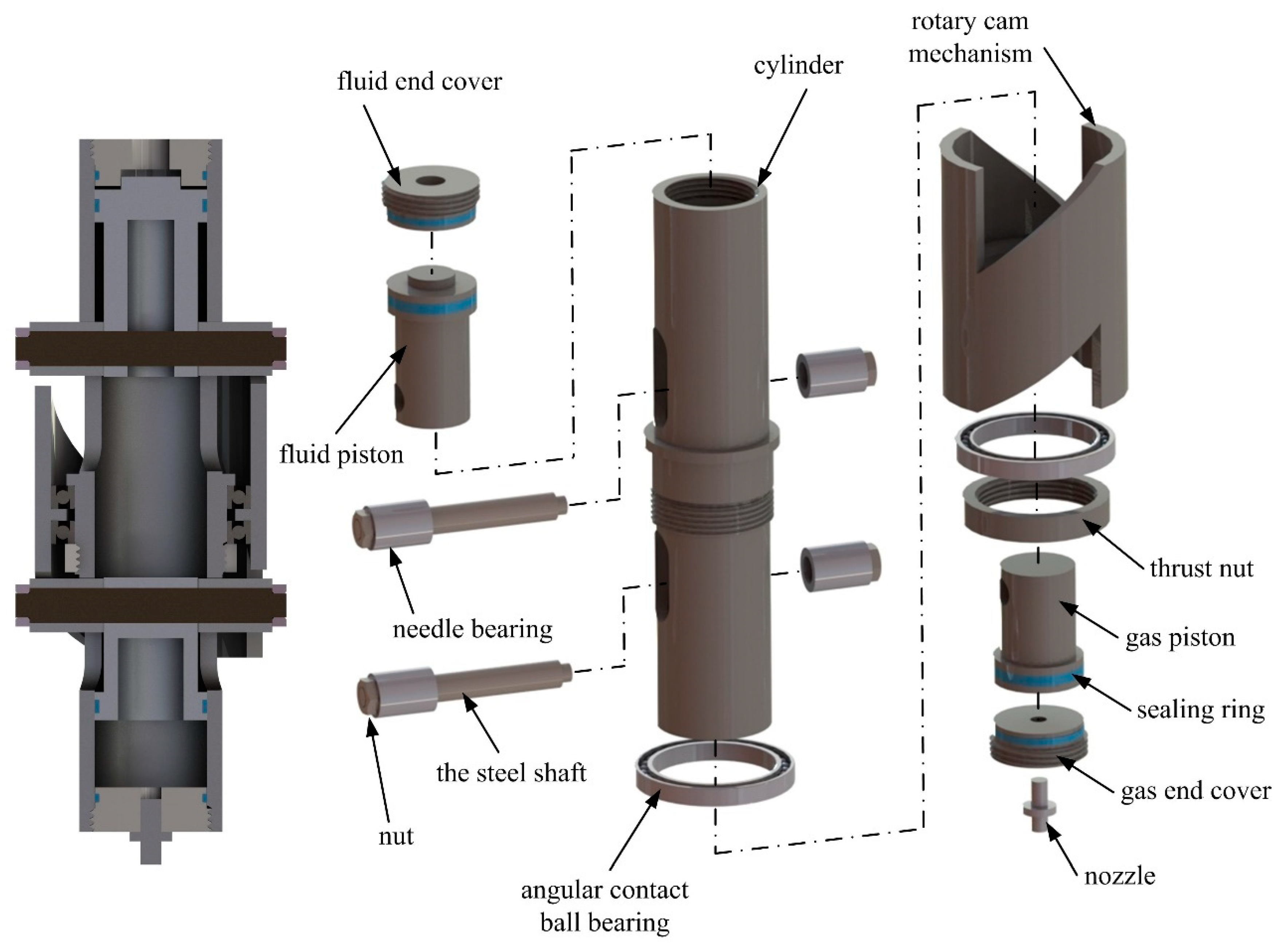
In this paper, a combined piston type hydraulic accumulator working with low pressure drop is designed. Contrary to a traditional piston type accumulator, the new accumulator’s fluid cavity and gas cavity both have a piston for sealing and transferring force. The two pistons are connected through a rotary cam mechanism. Using the nonlinear characteristic of the cam mechanism, the nonlinear relationship between the pressure and the volume of the gas can be offset, and the fluid pressure can be maintained in a relatively steady range. In
Section 2, the flow compensation process of the traditional accumulator in a steady system and a frequency increased system is described. The defect of the traditional accumulator is also discussed. In
Section 3, the structure design of the new accumulator is given, and the equation of the cam mechanism is built based on the energy equation. In
Section 4, the simulation models of the new accumulator and the single cylinder hydraulic system are constructed in the Amesim platform. The dynamic equations of the main components are presented. In
Section 5, the experimental platform is constructed based on the simulation model. The fluid pressures of the new accumulator with different pre-charge gas pressures are tested at a fixed flow rate. The comparison between the new accumulator and the traditional accumulator in a specific example as the working frequency instantly increases from 0.25 Hz to 0.5 Hz is discussed in detail. The effective regions of the new accumulator and the traditional accumulator are also gauged. In
Section 6, conclusions about the effectiveness of the new accumulator and future work are summarized.
2. Defect of the Traditional Accumulator in the Frequency Varied System
The fluid in a hydraulic system is supplied by the hydraulic pump. The flow rate is decided based on the system requirement. Although the variable pump has superiority in the flow rate regulation, considering its size and weight, people prefer to choose a fixed displacement pump in some small hydraulic systems. The flow rate regulation is achieved by the speed regulation of the motor or the engine. Moreover, because the velocity of the cylinder varies in a large range, the flow rate of the pump usually matches the average flow rate of the entire hydraulic system, and the fluctuation of the flow rate is compensated by the accumulator.
A typical single cylinder hydraulic system is depicted in
Figure 1. The diameters of the cylinder piston are 40 mm/20 mm, and the stroke length is 0.16 m. To simplify the analysis, the cylinder motion is designed as a 0.25 Hz sine wave, and the flow rate of the cylinder is calculated and illustrated in
Figure 1. The peak value of the flow rate in extension and retraction of the cylinder is different due to the different effective areas in the cap-end chamber and the rod-end chamber. The pump flow rate satisfies Equation (1):
where
is the pump flow rate,
is the flow rate of the entire hydraulic system, and
is the period time.
During a complete cycle of the cylinder motion, when the pump flow rate is lower than the cylinder flow rate, the accumulator compensates the flow rate with a decrease of pressure. When the pump flow rate is larger than the cylinder flow rate, the extra fluid oil flows into the accumulator. When the accumulator pressure achieves the rated pressure, the extra fluid oil flows through the relief valve. From the view of efficiency, the energy loss of the relief valve should be minimized. The pressure feature in a steady working system is that the pressure of the accumulator can get back to the rated pressure after an entire working cycle. The volume of the accumulator should satisfy Equation (2):
where
and
are the gas volumes of the accumulator in the lowest required pressure and the rated working pressure.
In a valve controlled system, the system pressure is usually higher than the working pressure of the cylinder. When the system pressure decreases, to ensure the actuator works well, the valve opening is increased. Since the valve opening has a maximum value, there is a minimum value for the system pressure under which the valve and the cylinder cannot work well. This minimum value is named as the lowest required pressure. Ignoring the uncertain disturbance at the force load, the working pressure of the actuator cylinder can be approximately calculated when given a certain motion. The lowest required pressure can be calculated from the working pressure and the pressure drop of the valve.
When the pump flow rate is equal to the average flow rate, the energy loss of the relief valve can be reduced to the minimum value. However, this pump flow rate is not robust enough for a frequency varied system. As shown in
Figure 2a, when the working frequency increases suddenly, the pump flow rate cannot match the new flow rate of the system immediately because of the hysteresis of the motor speed regulation. Therefore, there is a transition process between two different working frequencies. The transition process contains two stages: speed regulation stage and recovery stage. The speed regulation stage starts when the working frequency changes and ends when the pump flow rate matches the new average flow rate again. During the speed regulation stage, the fluid volume and the pressure in the accumulator decrease continuously. The recovery stage starts after the speed regulation stage and ends when the pressure returns to the rated pressure.
To reduce the difficulty of the analysis, the example model in
Figure 1 is idealized without force load and uncertain disturbance. Because the motion of the cylinder in the
Figure 1 is a sine wave, the working pressure increases when the motion frequency increases. Thus, the lowest required pressure increases as well. If the increase of the working frequency is large enough, the accumulator pressure drops below the lowest required pressure during the speed regulation stage, as illustrated in
Figure 2b. Therefore, the accuracy of the cylinder motion is affected during the transition process.
There are usually two ways to decrease the excessive pressure drop—increasing the pump flow rate or increasing the volume of the accumulator. The former increases the energy loss of the relief valve at low working frequency, and the latter increases the weight of the whole system. Considering energy efficiency and weight limit, the above-mentioned ways are not suitable for the small hydraulic system.
This defect of the traditional accumulator is due to the nonlinear characteristic of the gas. The exponential compression and expansion processes of the gas cause a large pressure variation during the working process. To ease this problem, the gas chamber and the fluid chamber in the accumulator should be isolated, and the force between the gas and the fluid should be transmitted through a nonlinear device. The nonlinear device is to offset the nonlinear variation of the gas pressure and maintain the fluid pressure in a steady area.
5. Simulation and Experiment Results
5.1. Experiment Platform
To test and compare flow compensation properties between the new accumulator and the traditional accumulator, a hydraulic platform based on the previous simulation model is erected, as shown in
Figure 7. There are two hydraulic circuits—the main actuator circuit and the force load circuit—in the experimental platform. The main circuit uses a three-phase asynchronous motor with 2.2 kw rated power and 2840 r/min rated speed to drive a constant displacement pump. The asynchronous motor is controlled by a SIEMENS frequency inverter. The actuator cylinder is connected to a Hoyea proportional valve BFWNE-02-3C2-32 with electrical position feedback. To ensure the steady of the force load, the flow in the force load circuit is sufficiently supplie by another motor and pump. Rated pressures in the main circuit and the force load circuit are set to 63 bar and 35 bar. The two cylinders with the same size are deployed in the main circuit and the force load circuit. The motion of the actuator cylinder rod is measured by a linear displacement transducer. The working pressure of the main circuit is measured by a pressure transducer. An ADVANTECH PCI-1716 data acquisition card is used to convert the analog signals and send out the valve command. The parameters of the main components of the experiment platform are shown in
Table 1.
5.2. Fluid Pressures with Different Pre-Charge Pressures
To verify the effectiveness of the new accumulator design, a preliminary experiment focusing on the steady of the fluid pressure is conducted in this subsection. The first experiment is to gauge the fluid pressure when the fluid flows in and out from the new accumulator at a fixed flow rate.
In
Figure 8, the red lines are three ideal fluid pressures, 15 bar, 40 bar, and 70 bar. The pre-charge gas pressure is calculated from Equation (12). The lines with symbols are real fluid pressures tested by the experiment at a steady piston speed of 0.02 m/s. The pressures during acceleration and deceleration processes are not illustrated in this figure. The black arrow indicates the flow direction of the new accumulator. With the effect of the friction, the real fluid pressure when the fluid flows in is larger than the real fluid pressure when the fluid flows out. Therefore, the new accumulator has two levels of pressure, high pressure and low pressure. As shown in
Figure 8, when the ideal fluid pressure is 15 bar, the average gap between the ideal fluid pressure and real fluid pressure is 1.2 bar. Meanwhile the fluid pressure can maintain almost steady at a certain value, which means the variation of the pressure gap can be neglected in low pressure. When the ideal fluid pressure increases to 40 bar, the average pressure gap increases to 2.8 bar. Moreover, the pressure gap increases with the increase of the fluid charging percent. The maximum variation of the pressure gap is 0.5 bar at the 40 bar ideal pressure. When the ideal fluid pressure increases to 70 bar, the average pressure gap increases to 4.5 bar. The maximum variation of the pressure gap increases to 1.8 bar at the 70 bar ideal pressure.
As discussed in the previous sections, the pressure gap is mainly caused by the friction of the new accumulator. Because the friction in the new accumulator increases with the increase of the pressure, the pressure gap in the high pressure is larger than that in the low pressure. The variation of the pressure gap increases with the increase of the pressure, which is mainly due to the inaccuracy of the ideal gas equation at the high pressure. Another pressure characteristic is that the pressure gap when the fluid flows in is larger than the pressure gap when the fluid flows out. This is due to the different lubrication conditions of the two processes.
5.3. Comparison in A Large Instant Flow Compensation Process
To show the different flow compensation properties of the two accumulators, a detailed experiment with working frequency instantly increasing from 0.25 Hz to 0.5 Hz is tested. Based on the average flow rate, the pump speeds are set to 820 r/min and 1700 r/min, correspondingly. The first 4 s in the experiment represent the fluid charging stage. In this stage, the motor starts from zero speed to the fixed speed, and the accumulator is charged from pre-charged pressure to the rated pressure. The sine signal starts at the fourth second, and the working frequency is set to 0.25 Hz. After two entire cycles, the working frequency increases instantly from 0.25 Hz to 0.5 Hz. Then, the motor is regulated to 1700 r/min to match the new average flow rate. The flow compensation properties of the two accumulators are compared in three stages—0.25 Hz steady stage at 4–12 s, transition stage at 12–18 s, and 0.5 Hz steady stage at 18–24 s.
5.3.1. Pressure Comparison
To achieve a smooth simulation curve, some parameters in the Amesim model, such as the stiffness of the hoses and the flow rate pressure gradient of the relief valve, are tuned reasonably. Additionally, flow rate of the pump is carefully designed based on the required motion. Therefore, during the two steady stages and the transition stage, there is little fluid flowing through the relief valve. For a better speed regulation, the parameters of the asynchronous motor are considered in the Amesim model. Moreover, some noise from the transducer is removed.
As shown in
Figure 9, the charging process of the accumulator begins from 0 s. Before the new accumulator is fully charged, the fluid pressure can maintain an approximate steady value. There is an end to the cam profile, as shown in
Figure 3. When the needle bearing reaches the end of the cam profile, the new accumulator is fully charged, and the fluid pressure increases and reaches the cracking pressure of the relief valve. Therefore, when the new accumulator is fully charged at approximately 3 s, there is a pressure increment from the new accumulator pressure to the cracking pressure of the relief valve.
When working in two steady stages, the fluid pressures of the two accumulators vibrate regularly. Fluid pressures in both accumulators can return to the initial levels at the end of each working cycle. The oscillation of the pressure is continuous and derivable in the traditional accumulator. The oscillation of the pressure is rectangular in the new accumulator. Through the transformation of the cam mechanism, the pressure in the new accumulator keeps approximately constant if the flow direction is not changed.
When the frequency of the sine signal suddenly increases from 0.25 Hz to 0.5 Hz, the flow of the pump cannot match the requirement instantly, and the accumulator supplies the extra flow. The transition stage consists of the speed regulation stage and the pressure recovery stage. Before the motor speed reaches the new value, the pressure of the traditional accumulator continuously decreases and falls below the lowest required pressure. After the speed regulation phase, the pressure gradually recovers to the steady area. It is different in the new accumulator that the pressure can still vibrate in a steady area.
5.3.2. Comparison of the Valve Motions
As shown in
Figure 10, when working in two steady stages, the proportional valves in the two systems move regularly. Because the pressure in the traditional accumulator vibrates continuously, the motion of the valve is continuous, too. The valve motion in the new accumulator system is slightly different than that in the traditional accumulator system. The opening percent of the valve quickly increases or decreases when the pressure in the new accumulator vibrates from low pressure to high pressure.
During the transition stage, the pressure in the traditional accumulator falls below the lowest required pressure. In this condition, the valve command saturates, and the valve is fully open. After the speed regulation phase, the pressure recovers gradually, and the valve control returns to normal. Compared with the traditional accumulator system, the valve can still work well in the new accumulator system because of the special pressure characteristic.
5.3.3. Cylinder Motion Comparison
During two steady stages, the motions of the actuator cylinders in the two systems can both stably track the input signal by the PID algorithm, as shown in
Figure 11. The two tracking errors both increase with the increase of the working frequency. Moreover, due to the extra inertia load and friction, the cylinder motion in the new accumulator system has a small phase delay compared with the traditional accumulator system. The tracking error in the new accumulator system is slightly larger than that in the traditional accumulator system.
However, during the speed regulation phase, the tracking error of the traditional accumulator system increases obviously, while the tracking error of the new accumulator system can still vary steadily. Because the valve command saturates, the cylinder of the traditional accumulator system cannot track well. In this situation, the maximum tracking error of the traditional accumulator system is about two times larger than that of the new accumulator system.
5.4. Effective Region of the Traditional Accumulator and the New Accumulator
The increment of working frequency from 0 Hz to 0.4 Hz is tested to achieve the effective regions of the traditional accumulator and the new accumulator. The horizontal axis is the working frequency increment with the basic frequency 0.25 Hz. As shown in
Figure 10, when the increment is zero, pressures of two accumulator are all higher than the lowest required pressure, which means the two accumulators can work well in this working frequency. With the increment increases, the lowest pressure of the traditional accumulator decreases exponentially during the transition process. The high pressure and the low pressure of the new accumulator increases and decreases gradually. The lowest required pressure of the system also increases. When the increment increases to 0.18 Hz, the pressure curve of the traditional accumulator is equal with the lowest required pressure curve, which is illustrated as point A in
Figure 10. In other words, the increment 0.18 Hz is a critical value for the traditional accumulator, above which the cylinder of the traditional accumulator system cannot track the desired motion well. Similarly, the new accumulator has two critical values of 0.31 Hz and 0.38 Hz, which are illustrated as point B and point C in
Figure 10. Since the value of point B is less than that of point C, the frequency value 0.31 Hz is the critical value for the new accumulator. As shown in
Figure 12, the frequency increment that the new accumulator can adjust is 0.13 Hz more than that of the traditional accumulator. Therefore, the new accumulator has a larger effective region than the traditional accumulator.
5.5. Energy Output of the Pump in the Two Systems
Although the new accumulator can maintain pressure in a transient large flow compensation, energy loss and efficiency should be analyzed for a better understanding and use of the new accumulator.
Based on the above experiment, the energies out of the pump in the two systems are measured, as shown in
Figure 13. During the first 4 s and the transition stage, the charging energy of the new accumulator system is larger than that of the traditional accumulator system. During the two steady stages, the mean values of the output power of the pump in the two systems are almost the same.
Due to the friction between the piston and the cylinder, there exists energy loss at the new accumulator, and the efficiency of the new accumulator is lower than the traditional accumulator. The energy efficiency of the new accumulator in the two steady stages can be simply calculated as Equation (20):
where
and
are the charging and the discharging pressures of the new accumulator. Using Equation (20), the efficiencies of the new accumulator during the two steady stages are 88.7% and 85.5%. Compared with the new accumulator, the traditional bladder type accumulator works with high efficiency and can be treated without energy loss in this paper.
6. Conclusions
To decrease the pressure drop of the traditional accumulator in the valve controlled hydraulic system when the system working frequency increases instantly, a new combined piston type accumulator is proposed in this paper. The entire structure is designed, and the mathematical equation of the cam mechanism is built based on the ideal gas equation. A simulation model is constructed in the Amesim platform, and an experimental platform is also built with the same parameters.
From the experimental results of the single cylinder system, the lowest pressure of the traditional accumulator decreases exponentially during the transition process. Under the basic working frequency 0.25 Hz, the critical values of the frequency increment are 0.18 Hz for the traditional accumulator and 0.31 Hz for the new accumulator. When the frequency increment is above the critical value, the cylinder cannot track the desired motion well, and the tracking error obviously increases during the transition process. An example as the working frequency instantly increases from 0.25 Hz to 0.5 Hz is tested. Results shows that, during the transition process, the pressure of the traditional accumulator system drops below the lowest required pressure, and the maximum tracking error is almost double that of the steady stage. On the contrary, the pressure and the tracking error of the new accumulator system can still maintain steady during the transition process.
Different from the traditional accumulator, the hydraulic force in the new accumulator is transferred through the steel shaft and the cam mechanism. Therefore, the pressure range of the new accumulator is limited to the flexural strength of the steel shaft and the contact strength of the cam mechanism. As shown in
Figure 8, the new accumulator works well in the low pressure, and the pressure curve deviates gradually from the ideal pressure in the medium pressure. Considering this fact, the prototype and the experiment are not validated in high pressure. The purpose of this paper is to propose a new type accumulator and validate it preliminarily.
Further research will concentrate on decreasing the piston friction and pressure oscillation amplitude of the new accumulator. The new accumulator’s structure should be further optimized for a more compact size and a larger pressure range. A more accurate gas equation, which is suitable from low pressure to high pressure, should be used to design the profile of the cam. Additionally, a detailed application in a specific small hydraulic system with the new accumulator will be studied.


