Abstract
In this study, a novel design concept of magnet-less, high response time electromagnetic valve actuator with high starting force for independent valve actuation control of internal combustion engines is proposed. The new actuator geometry design is based on the theoretical analysis of electromagnetic and mechanical properties of a curve shaped object rolling on a fixed surface, which may be either flat or curved. The prototype of the new electromagnetic valve actuator was built according to the results that were obtained with finite element based numerical modelling and analysis. Finally, the experimental measurements are performed and the theoretical predictions were confirmed by obtaining good agreement between the experimental and numerical simulation results.
1. Introduction
The current energy conversion technology of the internal combustion engines (ICE) is mainly based on the camshaft driven valve-train systems [1], which are extremely well developed and tested, cost-effective, and have a simple and robust design [1]. However, the main drawback of the conventional valve-train systems is that it does not allow for fully independent control of each individual valve [1,2,3,4,5]. Numerous solutions have been proposed in order to address this issue, including fully independent electromagnetic, hydraulic, and pneumatic actuation systems (i.e., cam-less driven valves) [5]. Namely, finding the appropriate solution for the independent valve actuation system would significantly contribute to the improvement of the performance, energy conversion and utilization of the existing conventional ICE (gasoline and diesel engines) and facilitate the fulfilment of the requirements defined by new environmental regulations [6]. In addition, it would enable further development and the introduction to the market of novel ICE engine operation mode, such as pneumatic hybrid [7], homogeneous charge compression ignition (HCCI) combustion [8,9], and 2/4 stroke operation mode [10], which have already been scientifically evaluated.
Promising candidates for fully independent valve system are electromagnetic based valve actuators [2,3,4]. Most popular among the proposed electromagnetic valve actuation solutions is the Pischinger EMV system [5,11]. The later versions of the valve actuator systems were upgraded with a permanent magnet core [2,3,4]. In addition to this system, there are many other electromechanical solutions and most of them have integrated permanent magnets [11,12]. However, the actuators having permanent magnets are expensive and they may be problematic when used in harsh physical environments with extremely high or low temperatures [13] as well as humidity and vibrations.
Another important challenge of the conventional ICE engine technology is finding an adequate valve timing optimization solution for better fuel economy and the efficient reduction of pollutant emissions [14,15]. This challenge in independent ICE valve electromagnetic control is being approached by developing an electromagnetic valve actuator design with an appropriate force-stroke characteristic, which would enable a high level of flexibility in valve timing control and lifting [2,5]. However, so far finding an appropriate solution for successful electromagnetic valve timing control has been a demanding task due to the pronounced nonlinearity of the force stroke characteristic and high landing velocity [2,4,11,12,16,17,18,19,20].
The primary goal of this study was to propose a novel design concept of magnet-less electromagnetic valve actuator with very short time response and high starting force characteristics for independent valve actuation control of internal combustion engines in order to enable more efficient energy conversion and to enhance the reliability of the whole system Moreover, the actuator should be able to stop or start the valve from any position. First, the novel design concept was established based on analytical analysis and further on confirmed by two-dimensional (2D) and three-dimensional (3D) finite element based numerical modelling and analysis. Second, the prototype of the new electromagnetic valve actuator was built and experimentally tested. Finally, the experimental measurements and numerical results were successfully compared. The proposed actuator can be also used in other fields of interest (e.g., cryogenic systems, systems in harsh physical conditions, etc.).
2. Theoretical Background and Overview of the Existing Electromagnetic Valve Actuators
Figure 1a illustrates the working principles of the conventional electromagnetic valve actuators (without permanent magnets). Depending on the electric current based magnetic flux density component that was used for the actuation, the conventional electromagnetic actuators can be classified, as follows: Type 1—based on the normal component of the magnetic flux density in the air-gap (Figure 1a); Type 2—based on the tangential component of the magnetic flux density in the air-gap (Figure 1a); and, Type 3—based on the combination of the Type1 and Type 2, where the air-gap surface is increased, but the acting force is still produced by the y-component of the normal component of the magnetic field density in the air-gap (Figure 1a). The comparison of the force-displacement curve shapes that were empirically obtained with the three different types of actuators is illustrated in Figure 1b.
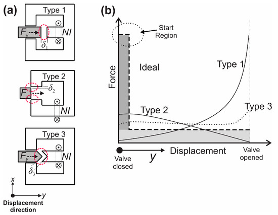
Figure 1.
(a) Conventional electromagnetic valve actuators. (b) The comparison of the force-displacement curve shapes obtained with three different types of actuators Type 1, Type 2, and Type 3 with the ideal one (within Ideal operating area-grey area, ideal force-displacement curve-dashed line).
Figure 1b shows that the force obtained with the actuator Type 1 is the highest at the end of the actuator displacement/stroke [13,14], however a very small force is produced at the beginning of stroke, when the highest force is needed for the ICE valve opening. The Type 2 actuator provides a more convenient force-displacement curve shape since it has higher force within the start, however its force at the end of the stroke is significantly smaller when compared to the force that was obtained with the Type 1 actuator. The force-stroke curve shape of actuator Type 1 can be modified to a new force-displacement shape curve by using Type 3 actuator (Figure 1a, Type 3), provided that the core pole shapes and the geometry of the air gap are properly designed [15,16,21]. Namely, the modification of the core pole shapes of the Type 3 actuator leads to a more flattened or constant force-displacement curve (Figure 1b, Type 3). However, the maximum output force that was obtained with the actuator Type 3 is much lower towards the opening displacement region when compared to the Type 1 (Figure 1b).
Therefore, the main disadvantage of all three above described actuator principles is the lack of the desired starting force intensity (i.e., indicated as the start region in Figure 1b), where the highest possible output force is needed in order to efficiently open the ICE valve. Figure 1b illustrates the theoretically ideal operating area of the ICE valve actuator (i.e., ideal force displacement curve represented with the dashed line). A high starting force is needed to overcome the pressure in the cylinder and for the acceleration of moving masses (Figure 1b, dark grey area). After the pressure equilibrium is achieved on both sides of the valve, the required force is only needed for the acceleration of the moving masses, so the required force can be reduced (Figure 1b, light grey area).
Based on the Maxwell stress tensor theory (1) and (2)), the Type 1 actuator uses the normal force component, while the Type 2 actuator uses the tangential force component on the moving part. The magnetic force (i.e., magnetic pressure acting on active surface A) components in vertical (normal) Fy and horizontal (tangential) direction Fx can be expressed with vertical (normal) By and horizontal (tangential) Bx components of magnetic flux densities (Figure 1a) from the central line of the air gap.
It is well known that the normal component of magnetic flux density in the closed proximity of the ferromagnetic object is few times larger than the tangential component (based on the general magnetic circuit design knowledge, e.g., electrical machines). When considering this statement and, based on (1) and (2), it can be explained why the magnetic force that was obtained with Type 1 actuator is much larger than the useful magnetic force obtained with actuator Type 2 or Type 3. Accordingly, we can deduce that the air gap must be as small as possible within all moving operational positions to achieve the maximal magnetic pressure.
As stated above, the existing electromagnetic valve actuators due to the low starting force do not meet the requirements for the valve control of ICE, which requires rapid valve open–close transitions (i.e., when great accelerations and decelerations during valve opening and closing occur). The accelerations and decelerations, together with the moving mass of the actuator mover and valve itself, require a large starting force of the actuator. In addition, the high starting force at beginning of opening stroke (Start Region in Figure 1b) is also needed to overcome the build-up pressure in ICE cylinder that is caused by remnant gases. Some existing conventional electromagnetic actuators solutions, such as Pischinger EMV system, try to accumulate or regenerate energy with springs. The problems of such systems are difficult starting procedure and week control between end positions [2,5]. Additionally, during the normal operation, the valve can stop only in fully open or fully closed position. In this study we propose a new concept of actuator geometric design without permanent magnets, with high starting force and with ability to start from and stop at any required position in order to overcome the listed drawbacks of the existing conventional electromagnetic actuators.
3. The Concept of the New Actuator Geometric Design
The concept of the new actuator was based on designing a proper actuator geometry being able to produce a high starting force (Start region in Figure 1b) and by using the normal component of magnetic flux density. The new actuator geometry design is based on the theoretical analysis of the electromagnetic and mechanical properties of a circle shaped object moving/rolling on a fixed (not moving) surface, which may be either flat or curved. The moving object represents the mover of the actuator and the fixed object presents the stator with the source of magnetic flux density, as illustrated in Figure 2a,b,d.
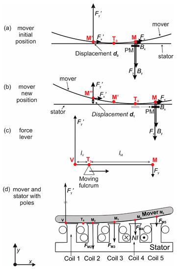
Figure 2.
(a) The actuator displacement d0 at the initial position of the mover, (b) a new position of the mover due to the movement of the permanent magnet PM with increased displacement d1 in y-direction (d0 > d1), (c) illustration of the first class lever mechanical advantage and (d) illustration of the mover over a fixed stator with five coils on teeth (only one energized) forming electromagnetic poles (EM poles).
The source of the magnetic flux density at the stator can be realized either by moving permanent magnet (as illustrated in Figure 2a,b, where stator should not be a ferromagnetic), or by fixed electromagnets on the stator side in form of magnetic poles (as illustrated in Figure 2d). Figure 2a illustrates the basic principle of the mover movement on a flat surface of the stator produced by moving a permanent magnet (PM in Figure 2b). At the initial position of the magnet (Figure 2a), the contact point between the stator and the mover is indicated with T0. At this position there is point M on the mover, at which the normal component of the magnetic flux density By is significantly larger than the horizontal component Bx and accordingly the vertical component of magnetic force (calculated from the magnetic force according to the (1) and (2) is Fy >> Fx.
Basically, the mechanical movement of the mover is created according to the first class lever principle, as shown in Figure 2c, where the contact point T0 between the stator and the mover represents the fulcrum (i.e., pivot point) moving from the point V up to the point M, the effort force is the electromagnetic force Fy (i.e., input or effort force) and the resistance is the load force Fy’ (i.e., output or load force). The fulcrum location determines the mechanical advantage of the lever, which is determined by dividing the distance from the fulcrum to the input or the effort force Fy (i.e., input arm lM) by the distance from the fulcrum to the output or load force Fy’ (i.e., output arm lV). Namely, the mechanical advantage lV/lM and the input vs. output force Fy/Fy’ ratio vary according to the basic equilibrium equation . Hence, the following mechanical advantages during the actuator mover movement are possible: lV/lM < 1 (i.e., Fy’ > Fy), lV/lM = 1 (Fy’ = Fy—initial mover position |M’T0|=|T0M| illustrated in Figure 3a) and lV/lM > 1 (i.e., Fy’ < Fy—the new mover position |M’’T0|>|T0M| illustrated in Figure 2b).
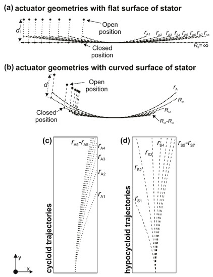
Figure 3.
Comparison of different actuator rolling surface geometries at the same scale resulting in the same actuator displacement/stroke: (a) actuators with different mover radii rA rolling on flat stator surface (Rs = ∞); (b) actuators with different mover radii rA rolling on curved stator surface with different Rs and (c) the comparison of cycloid (doted); and, (d) hypocycloid trajectories (dashed) obtained from same starting point due to different stator and mover radii.
Accordingly, a much larger force component in vertical direction Fy’ as compared to the horizontal component Fx’ is achieved due to the small air gap between the stator and the point M on the mover (Figure 2a). The source of magnetic field needs to be moved towards the mover rolling direction in order to achieve the desired moving effect and thus to produce the actuator stroke/displacement. As illustrated in Figure 2a, when the permanent magnet is moved in clockwise direction (to its new M position in Figure 2b), the initial point M from the initial position (in Figure 2a) touches the stator surface at the new point T0 (in Figure 2b). Accordingly, the initial point M’ renames to the point M’’ and the initial point T0 renames to the new point M’.
As stated above, the effect of the moving permanent magnet on the stator is replaced by the static (not moving) electromagnets that are designed as separate coils forming electromagnetic poles (EM poles) on the stator (i.e., five EM poles illustrated in Figure 2d). In this case, the movement of the mover can be obtained by the proper sequence of the electromagnetic pole excitation from the coil 1 to 5 (Figure 2d). Figure 2d represents the state of forces when the EM poles from 2 to 5 are energized.
At the starting position of the mover the valve is closed which is illustrated with the contact point T0 between the stator and the mover (T0 above the phase 1 in Figure 2d). The point V on the armature is also the mounting point of the valve V. As the mover starts to move/roll, due to the suppressed current in the coil 2 (Figure 2d) in clock wise direction the contact point T0 moves to the right along the stator surface. The valve mounting point V mainly moves in the vertical direction, away from the flat stator surface, and thus generates the effective stroke/displacement of the actuator. When the coils of the EM poles 2, 3, 4, and 5 are consequently electrically excited, the acting force on the mover above each stator pole is produced (FM2, FM3, FM4 and FM5). The value of the electromagnetic force above each pole depends on its current excitation and the size of air gap between each stator pole and the mover. At the starting position, the stator coils from 2 to 5 can be simultaneously electrically excited or in sequences starting from coil 2 and coil 3, followed by the excitation of the coil 3 and coil 4, and finally by the coil 4 and the coil 5. In conclusion, different combinations of coil excitations can be applied in order to obtain the desired actuator displacement. It should be noted that, in all cases, when the moving point T0 reaches the electrically excited pole’s symmetry, the current through pole’s coil must be deactivated (this is valid also for the case of coil excitation in the counter clock wise rolling direction). In this way, the resultant cumulative acting magnetic force Fy only in vertical (y) direction is obtained (FM2, FM3, FM4, and FM5, Figure 2d) while maintaining the air-gap small as possible in all active positions.
In addition to the actuator geometry that was introduced in Figure 2d (i.e., as the circle shaped mover rolling on a flat surface stator geometry), the stator and rotor can theoretically have an arbitrary geometry. Therefore, in this study, we analyzed and compared different combinations of stator and rotor geometries with the goal to design an actuator (Figure 2d) with the smallest possible dimensions meeting the requirements, such as high starting force and the target actuator displacements ranging from 0 mm to 5 mm.
We analytically analyzed and compared different mover geometries versus stator geometry combination by varying different mover curvatures and curvatures of the stator geometry, ranging from the flat stator surface (stator radius Rs = ∞) up to the curved stator surface (with different radii Rs).
The comparison of actuators with different mover geometries (with different mover radii rA) rolling on flat stator surface (Rs = ∞) resulting in the same displacement d is shown in Figure 3a. Based on this comparison it can be observed that with increasing the radius of the mover the dimensions of the whole actuator are also increasing while preserving the displacement d. Figure 3a also shows different moving trajectories of the mover, depending on its arc radius. The goal is to achieve as minimal as possible mounting point V movement in x-direction and desired y-movement (stroke length) while also maximizing the electromagnetic force at the valve mounting point describing the cycloid trajectories on Figure 3a). For example, a smaller mover arc radius means larger valve mounting the point movement in horizontal direction (i.e., x direction), which is not desired. This means that the overall actuator dimensions and the active air gap using the curvature geometries that are presented in Figure 3b can be smaller, as compared to the curvature geometry designs that are shown in Figure 3a for the same displacement/stroke (d).
In addition, according to the upper description, the highest starting force is expected for the curvature geometries that are shown in Figure 3b for the same actuator size. Moreover, a straighter valve mounting point movement is enabled. The comparison of cycloid (doted) and hypocycloid trajectories (dashed) that was obtained from same starting point is shown in Figure 3c,d respectively. Therefore, the novel design concept of electromagnetic valve actuator is based on the geometry of curved mover rolling on the curved stator surface (Figure 3b) forming hypocycloid trajectories.
4. Numerical Modelling
The numerical model and the prototyped actuator geometry that we developed and realized in this study are based on the preliminary analytical results of the mover and the stator rolling surface curvature. In order to optimize the actuator, we performed numerical modelling by using finite element modelling (FEM) approach. The 3D initial geometry of the valve actuator model with main geometric parameters (stator and mover length L, stator height Hs, stator width Ws, mover width Wa and mover height Ha) is displayed in XY and YZ cross section view in Figure 4a. Based on this model, we performed parametric analysis and optimization by varying the stator and rotor geometric parameters. The parametric analysis was carried out by rocking the mover in increments of 1 degree on the stator surface during the actuation cycle (i.e., from the opening to the closing of the actuator). For each resulting actuator geometry, we calculated and analyzed the magnetic flux density distribution B within the actuator and the resulting electromagnetic output force F by performing magneto-static analysis. The final geometry was achieved when the target actuator displacements that ranged from 0 mm to 5 mm was obtained based on analytical analyses (Figure 3), and when the highest possible electromagnetic force at the beginning of the actuation cycle was produced with the optimal magnetic flux density distribution by applying FEM. The resulting radius of the mover curvature was rA = 102.8 mm and the stator radius curvature was Rs = 137.51 mm. The resulting geometry with the geometry parameters that are given in Table 1 was selected as final geometry for the new actuator prototyping and experimental work.
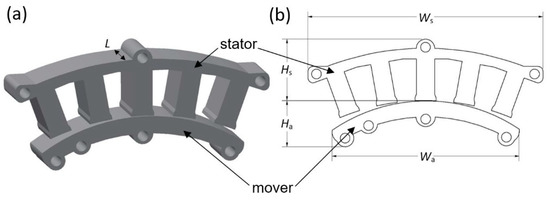
Figure 4.
(a) The three-dimensional (3D) geometry of the valve actuator and (b) XY and YZ cross section view with five poles with the indicated geometrical parameters.

Table 1.
The calculated geometrical parameters of the final actuator geometry used for prototyping and experimental work.
The ferromagnetic material M350-35A was applied for both the stator and the mover core. The actuator was surrounded by a large air region with the applied Dirichlet boundary condition on its outer surface. The applied current I for each energized coil was limited by the current density set to 4 A/mm2. Different combinations of simultaneously energized phases were analyzed. The coils of each phase were wounded with cooper wire, with diameter 1.3 mm and N = 28 turns. The slot cross section surface was 181 mm2.
5. Experimental Measurements
Two sets of experimental measurements were performed: multi-static and dynamic. Within the first part of the experimental study, the multi-static measurement was performed in order to acquire the characteristics of force versus displacement during one actuation cycle (from opening to closing) of the prototyped actuator.
The multi-static experimental force measurements were performed with a PC controlled motorized test stand with ±5000 N load cell.
The actuator displacement was controlled with the motorized test stand system achieving quasi static states (no transients) and the force was measured during the entire opening-closing cycle of the actuator (i.e., the force was measured for the displacements that ranged from the initial/closed position up to the maximum displacement and back to the initial position of the actuator). During the measurement, the active coils were connected in series and energized (i.e., excited with the current supply) in four different coil combinations: Combination 1—active coils were 2, 3, 4, and 5; Combination 2—active coils were 3, 4, and 5; Combination 3—active coils were 4 and 5; and, Combination 4—only coil 5 was active.
Since the multi-static experimental set up does not enable the dynamic assessment of the actual initial starting force Fy the dynamic measurements procedure was performed. Additional dynamic measurements were performed with the Triaxial Accelerometer (DeltaTron®, Bruel & Kjaer). The data acquisition was performed with a high speed USB National Instruments carrier interface. The standard Kalman filter was applied to process the experimentally measured data of accelerations. The accelerations data were converted into the force Fy, according to the second Newton’s law , where the valve system friction was neglected. The total mass of the valve and its mounting part was m = 0.201 kg. At the beginning of each measurement, the sensor was zeroed with respect to the gravitational force. During the measurement the mover was positioned so that the gravitational force acted in the opposite direction with respect to the produced force, meaning that the measured forces were not over valuated. Therefore, the influences of the gravitational force were neglected due to the expected high starting forces.
6. Results and Discussion
The comparison of experimentally measured (i.e., by performing multi-static measurements) and the numerically calculated electromagnetic force (Fy) as a function of the actuator displacement (d) for different combinations of coil activations is shown in Figure 5 The comparison of F(d) characteristics that were obtained with simultaneous activation of the coils 2, 3, 4, and 5 is shown in Figure 5a, and the Figure 5b shows the results obtained with activation of for the coils 3, 4, and 5. Figure 5c shows the results obtained with simultaneous activation of the coils 4 and 5, while the Figure 5d shows the results obtained by the activation of the coil 5 only. The results that are shown in Figure 5 are obtained with the DC current I = 25 A applied to the selected active coil combinations. In all numerical simulations the number of coil turns was N = 28 for each pole (note: the values of I = 25 A and N = 28 are calculated according to the required current density, the slot surface Aslot = 181 mm2, and the slot fill factor kcu = 0.4).
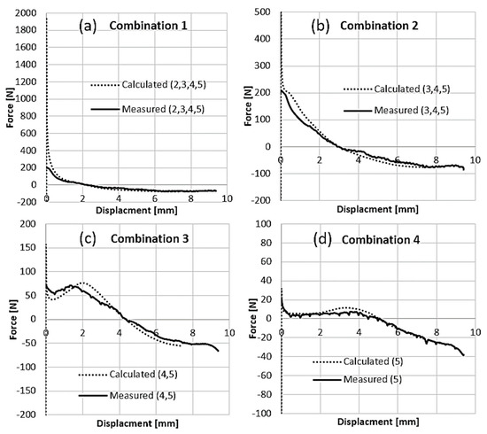
Figure 5.
The comparison of experimentally measured (multi-static) and the numerically calculated magneto-static force obtained with different combinations of coil activation: (a) Combination 1, (b) Combination 2, (c) Combination 3, and (d) Combination 4.
One of the main advantages of the developed actuator is that the desired force-displacement characteristic F(d) can be designed/shaped by combining different coil activation (i.e., by switching on and off the coils of the five actuator phases). The resulting force-displacement characteristic (grey curve) that was obtained with different coil combinations is shown in Figure 6a. The first part of the calculated curve (within the displacement range (0 < d < 0.33 mm) represents the resulting actuator force of 1850 N that was obtained by simultaneous activation of the coils 2, 3, 4, and 5. At the intersection of this F(d) curve and the F(d) curve obtained as a result of activation of the coils 3, 4, and 5 (the switching point S2 in Figure 6) the coil 2 should be deactivated (note: if the coil 2 is not deactivated the significant breaking force acting on the actuator mover may occur). Further, at the intersection point (the switching point S3 in Figure 6) of the F(d) curve obtained with the activation of the coils 3, 4, and 5 and the activation the coils 4 and 5 the phase 3 must be deactivated. Finally, at the switching point S4 where the F(d) curves that were obtained with the simultaneous activation of the coils 4 and 5 and the coil 5 only intersect, the coil 4 should be deactivated. Figure 6b shows the zoomed F(d) characteristic for the coil switching S3 and S4, where the actuator displacements from d = 1.7 mm up to d = 5 mm (i.e., which is the closing position of the actuator with F = 0 N) were obtained in order to more clearly provide the obtained values of electromagnetic forces within this area. The force that was obtained at d = 1.7 mm was F = 72 N (the switching point S3) and the force obtained at d = 4.15 mm (the switching point S4) was F = 10 N.
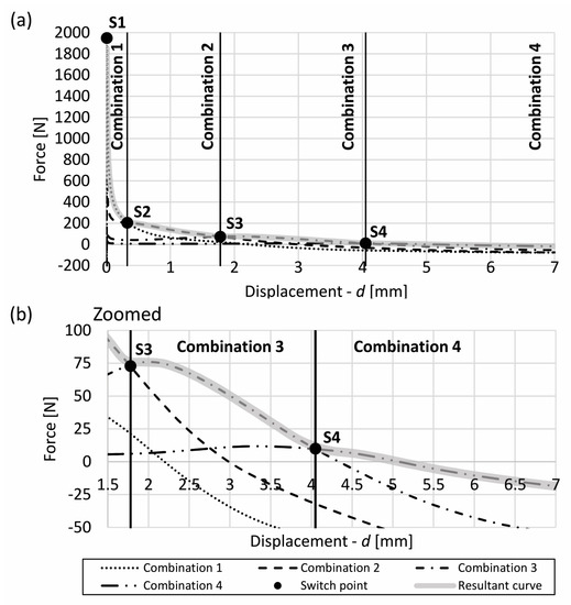
Figure 6.
The resulting multi-static force-displacement F(d) characteristic obtained with different combinations of coil activations (a) F(d) during the entire actuation cycle and (b) zoomed F(d) for the displacements obtained with simultaneous activation of coils 4 and 5 and with activation of the coil 5 only.
The normalized distribution of the magnetic flux density vectors in the XY cross section plain of the numerical model that was obtained at the characteristic coil switching points (i.e., actuator displacements) is shown in Figure 7. The numerically calculated magnetic pressure (N/m2) distribution in the XY cross section view and the actuator displacements obtained at four different characteristic coil switching points S1, S2, S3, and S4 are shown in Figure 8 for each of the coil combination. The results in the Figure 7a show that the majority of magnetic flux density B obtained within the ferromagnetic material at the switching point position S1 with the energized coil Combination 1 is acting in front of the point S1 mainly on the EM pole 2 producing the valve opening force (Figure 8a). Similarly, the same effect is observed for the switching points S2 (Figure 7b and Figure 8b), S3 (Figure 7c and Figure 8c), and S4 (Figure 7d and Figure 8d). Accordingly, the results in Figure 8 demonstrate that the largest surface force is produced in the area where the largest B was obtained: phase 2—Figure 8a, phase 3—Figure 8b, phase 4—the Figure 8c, and phase 5—Figure 8d.
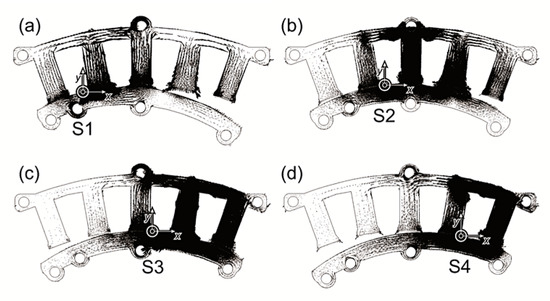
Figure 7.
The normalized distribution of the magnetic flux density vectors: (a) S1, (b) S2, (c) S3, and (d) S4.
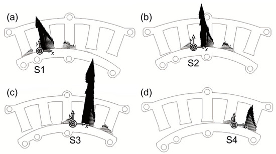
Figure 8.
The numerically calculated and normalized surface force (N/m2) distribution (XY cross section) at the characteristic coil switching points: (a) S1, (b) S2, (c) S3, and (d) S4.
The normalized surface forces in Figure 8b,c are higher than in the position shown in Figure 8a, while the actual valve force is decreasing (Figure 8) from position in Figure 8a to the final position Figure 8d. This is due to the lever ratio (Figure 2c) changing during rocking.
Figure 5 and Figure 6 show good agreement between multi-static measurements and the numerical magneto-static calculation obtained for displacements d > 0.33 mm up to the closing of the actuator d = 5 mm where F = 0 N. However, a large deviation between the calculated and measured results of the starting force is observed within the actuator opening stage for the displacements 0 mm < d < 0.33 mm (Figure 6—displacements obtained by energizing the coils of the EM poles 2, 3, 4, and 5). This problem can be attributed to the effects of the strong electromagnetic forces occurring during the experimental measurements. Namely, when the current excitation was applied to the selected coil combination (2, 3, 4, and 5), an undesirable/unexpected mechanical deformation of the connecting components mainly the between mover and the cradle/housing system was observed, as shown in Figure 9a—exploded view of the prototyped actuator and in Figure 9b—the actuator and its cradles/housing during the experimental measurement. Instead of being transferred to the measuring sensor, the resulting force was redirected to the cradle/housing system, causing a pronounced deformation. Due to this problem we were not able to experimentally detect the actual response of the actuator by performing multi-static measurements.
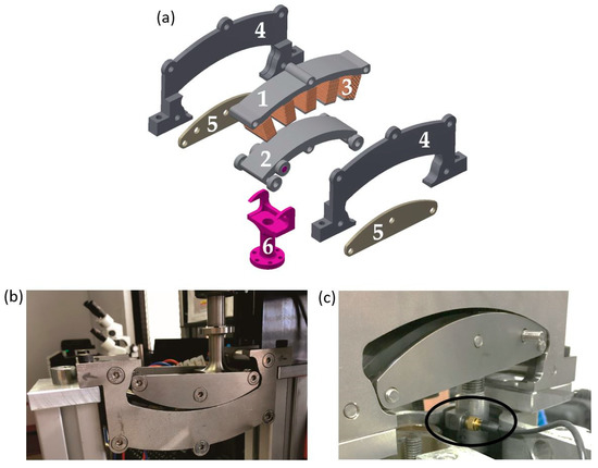
Figure 9.
(a) The exploded view of the prototyped actuator composed of the following components: 1. stator, 2. mover, 3. coil winding (on the stator poles), 4. stator cradle (stationary component), 5. mover cradle (movable–rolling component) and 6. output component (the connecting part to the valve); (b) actuator and its cradles/housing during the experimental force measurements; and, (c) the actuator mounted on the valve of single cylinder engine with the accelerometer.
Therefore, the dynamic response of the actuator was experimentally measured in order to more precisely acquire the actual force signal within the initial stage of the actuator opening. The dynamic measurements were performed with an accelerometer sensor in order to adapt the experimental set-up measurement system to the characteristics the actuator and to more precisely simulate the realistic behaviour of the prototyped actuator. Hence, such adapted dynamic measurement set up enabled us to more precisely detect the actual resulting starting force of the valve before it was transferred to the deformation of the cradle/housing system during the experiments (Figure 9). We mounted the actuator to the one of the valves on the single cylinder internal combustion engine in order to perform the measurements as accurately as possible. The accelerometer was positioned on the connecting element between the mover and the valve system (as shown in Figure 9c). The maximum upper limit of the measurements range of the used accelerometer sensor was 500 G. The acquired signal profile of the time response of the actuator acceleration that was first processed by using standard Kalman filter is displayed in Figure 10.
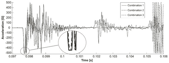
Figure 10.
The measured time profile of the actuator acceleration acquired by performing dynamic measurement.
The zoomed area of the acceleration profile that is shown in Figure 10 indicates that the initial measured acceleration was above the accelerometer range, which means that the actual acceleration during the experiments clearly exceeded the maximum value of 500 G. The experimental results are shown for the actuator accelerations that were obtained with the Combination 1 (active coils 2, 3, 4, and 5), Combination 2 (active coils 3, 4, and 5), and Combination 3 (active coils 4 and 5). The last case when only the phase 5 was active is not shown due to the fact that a very small force was produced, due to a very large air gap forming below the pole 5 within the starting position of the mover.
The measured data of the acceleration shown in Figure 10 are then converted into force F(t) signal according to the second Newton law, where the valve stem friction was neglected. Figure 11 displays the obtained results of the force. As shown in the Figure 11, the maximum displayed starting force was around 1000 N. However, it should be noted that the actual starting forces even exceeded the value of F = 1000 N, due to the fact that higher accelerations exceeding the maximum range of the accelerometer 500 G occurred during the experiment, as shown in the Figure 10 (the zoomed area of the acceleration signal).
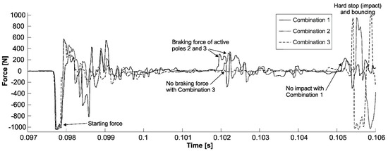
Figure 11.
The comparison of the measured forces during the actuator stroke obtained with different excitation combinations.
From Figure 11 it can be seen that the actuator achieves the starting force F = 1000 N in t = 80 µs at any coil excitation Combination. In the middle of valve opening cycle, with coil excitation Combination 1 and Combination 2, noticeable breaking forces are observed (Figure 11). The strongest breaking force is obtained with coil Combination 1. Thus, the valve stops without impact. With coil Combination 2, the valve impact is somewhat delayed (i.e., longer travel duration due to the breaking forces), and it is not so intensive as with excitation Combination 3. There is no breaking observed with excitation Combination 3, the valve impact occurs at the end of the stroke in the shortest time and it is the most intensive. The first impact (in Combination 3) is followed by a large valve bouncing. This can be explained through Figure 5a–c, where zero force crossing depends on excitation Combination, therefore the breaking occurs at a different displacement. As a result of energized Combination 1, the breaking occurs after 2 mm of displacement, while at Combination 2, breaking occurs after 3 mm, and with energized Combination 3, the breaking appears after 4 mm of displacement. During the mover rocking movement progress the mover barycentre is changing, which results in an increasing of active inertia. The accumulating force is adding to the acting electromagnetic accelerating force obtained with Combination 3, which results in higher accelerations and in higher decelerations during the impact.
By performing these dynamic measurements, we were able to more precisely detect the actual higher values of the starting forces. Based on this, we explained the deviation between calculated and measured values that were obtained with multi-static measurements shown in Figure 5. Therefore, we confirmed the occurrence of the high starting force observed almost in all calculated force-displacements F(d) characteristics by using numerical magneto-static analysis.
Within the final part of this study, we numerically examined the influence of the number of coil turns N on the resulting F(d) characteristics by using magneto-static analysis. The coil turn number analysis was based on the fact that the electric time constant of the actuator still remains several times lower than its mechanical time constant. This means that an increase in coil number will not influence the actuator time response and it would increase the starting mechanical force response of the actuator. Therefore, we increased the number of coil turns by taking into account the most common standard automotive specifications for engine compartment components, which dictate the thermal operating conditions in the range from −40 °C to +140 °C and the supply voltage conditions from 9 V to 16 V. By considering these specifications, the mechanical time constant and the available winding space, we selected the windings with thinner wire and increased the number of coil turns to N = 91 turns (other parameters of the actuator were not modified). In this case, at the most demanding working point at +140 °C and 9 V we can still get currents 25 A (that results in 2275 Ampere-turns). The resulted F(d) characteristic that was obtained with an increased number of turns is shown in Figure 12. The increase in number of turns from N = 28 to N = 91 resulted in approximately three times higher output electromagnetic force (i.e., F = 7000 N in Figure 12a) as compared to the force that was obtained with N = 28 with the same supply current I = 25 A, as shown in Figure 5.
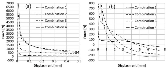
Figure 12.
F(d) characteristics obtained with 2275 ampere-turns. The F(d) characteristics are displayed: (a) for the initial part of the actuation cycle from 0mm up to 0.5 mm, (b) for the rest of the actuation cycle—for the displacements 0.5mm < d < 5 mm.
7. Conclusions
In this work, a novel design concept of electromagnetic valve actuator with high starting force for independent valve actuation control of internal combustion engines is proposed. The design concept of electromagnetic valve actuator that is presented in this study is based on the geometry of curved mover rolling on the curved stator surface forming hypocycloid trajectories with minimum deviation in useless horizontal displacement.
Based on the finite element numerical analysis, we successfully calculated/optimized the final actuator design that is used for the prototyping. Finally, the proposed novel design concept of the new electromagnetic actuator is experimentally confirmed by a good agreement between the experimental and numerical results. To the best of the author knowledge, this is the first study to propose the design concept of an electromagnetic valve actuator being able to produce the experimentally confirmed starting force up to 1000 N (at given actuator volume and current) and with numerically calculated capability to develop more than 7000 N.
Other important advantages of the novel actuator as compared to the existing electromagnetic actuators that are available in industry and research domains include cost effectiveness due to the absence of permanent magnets, relatively small dimensions, and high reactions speed. The actuator also allows for different force vs. displacement characteristics being controlled by switching/energizing different coil or coil combinations.
Author Contributions
Authors T.M., D.M. and S.Č. contributed to the analysis of analytical, numerical and experimental results, wrote and revised the manuscript. T.M. and D.M. designed the actuator and T.M. performed experimental measurements.
Funding
This research was funded by European Union’s Horizon 2020 research and innovation program under the grant agreement No. 824314.
Acknowledgments
The authors would like to thank the EU project VISION-xEV, Virtual Component and System Integration for Efficient Electrified Vehicle Development which has received funding from the European Union’s Horizon 2020 research and innovation program under grant agreement No 824314. This research study was also conducted and partially co-financed by the European Social Fund of the European Union within the framework of the Operational Program for Human Resources Development for the period 2007-2013: doctoral study scholarship schemes.
Conflicts of Interest
The authors declare no conflict of interest.
References
- Hara, S.; Suga, S.; Watanabe, S.; Nakamura, M. Variable valve actuation systems for environmentally friendly engines. Hitachi Rev. 2009, 58, 319–324. [Google Scholar]
- Cope, D.; Wright, A.; Corcoran, C.; Pasch, K.; Fischer, D. Fully Flexible Electromagnetic Valve Actuator: Design, Modeling, and Measurements; SAE Technical Paper: Warrendale, PA, USA, 2008. [Google Scholar] [CrossRef]
- Lequesne, B. Design and optimization of two-spring linear actuators. Eur. Trans. Electr. Power 1999, 9, 377–383. [Google Scholar] [CrossRef]
- Yang, Y.; Liu, J.; Lu, P.; Cheng, Y.; Ye, D. Multifunctional optimal design of an electromagnetic valve actuator with hybrid magnetomotive force for a camless engine. In Proceedings of the 2011 International Conference on Electrical Machines and Systems, Beijing, China, 20–23 August 2011; pp. 1–6. [Google Scholar] [CrossRef]
- Chladny, R.R.; Koch, C.R.; Lynch, A.F. Modeling automotive gas-exchange solenoid valve actuators. IEEE Trans. Magn. 2005, 41, 1155–1162. [Google Scholar] [CrossRef]
- Pischger, M.; Salber, W.; Staay, F.V.D.; Baumgarten, H.; Kemper, H. Low Fuel consumption and low emissions—Electromechanical valvetrain in vehicle operation. Int. J. Autom. Technol. 2000, 1, 17–25. [Google Scholar]
- Trajkovic, S.; Tunestål, P.; Johansson, B.; Carlson, U.; Höglund, A. Introductory Study of Variable Valve Actuation for Pneumatic Hybridization; SAE Technical Paper: Warrendale, PA, USA, 2007. [Google Scholar] [CrossRef]
- Charalambides, A.G. Homogenous Charge Compression Ignition (HCCI) Engines. In Advances in Internal Combustion Engines and Fuel Technologies; Ng, H.K., Ed.; IntechOpen: Rijeka, Croatia, 2013. [Google Scholar] [CrossRef]
- Rebhan, M.; Stokes, J. Two-stroke/four-stroke multicylinder gasoline engine for downsizing applications. MTZ Worldw. 2009, 70, 40–45. [Google Scholar] [CrossRef]
- Qiu, Y.; Perreault, D.J.; Keim, T.A.; Kassakian, J.G.; Fellow, L. Optimal Cam Design and System Control for an Electromechanical Engine Valve Drive. In Proceedings of the 2010 IEEE International Conference on Industrial Technology, Vina del Mar, Chile, 14–17 March 2010; pp. 565–572. [Google Scholar]
- Lee, S.H.; Yi, H.C.; Han, K.; Kim, J.H. Genetic Algorithm-Based Design Optimization of Electromagnetic Valve Actuators in Combustion Engines. Energies 2015, 8, 13222–13230. [Google Scholar] [CrossRef]
- Sjökvist, S. Demagnetization Studies on Permanent Magnets: Comparing FEM Simulations with Experiments. Ph.D. Dissertation, Acta Universitatis Upsaliensis, Uppsala, Sweden, 2014; p. 43. [Google Scholar]
- Mahajan, D.P.; Narayanaswamy, R.; Bavisetti, S. Saw-tooth pole solenoid actuator for aerospace applications. In Proceedings of the 2013 IEEE 8th Conference on Industrial Electronics and Applications (ICIEA), Melbourne, VIC, Australia, 19–21 June 2013; pp. 1353–1357. [Google Scholar] [CrossRef]
- Bao, J.; Vrijsen, N.H.; Gysen, B.L.J.; Sprangers, R.L.J.; Lomonova, E.A. Optimization of the Force Density for Medium-Stroke Reluctance Actuators. IEEE Trans. Ind. Appl. 2014, 50, 3194–3202. [Google Scholar] [CrossRef]
- Malamov, D.; Hadzhiev, I.; Yatchev, I. Influence of the pole shapes on the force characteristics of a DC solenoid actuator. In Proceedings of the 2017 15th International Conference on Electrical Machines, Drives and Power Systems (ELMA), Sofia, Bulgaria, 1–3 June 2017; pp. 435–438. [Google Scholar] [CrossRef]
- Plavec, E.; Vidović, M. Genetic algorithm based plunger shape optimization of DC solenoid electromagnetic actuator. In Proceedings of the 2016 24th Telecommunications Forum (TELFOR), Belgrade, Serbia, 22–23 December 2016; pp. 1–4. [Google Scholar] [CrossRef]
- Hu, M.; Chang, S.; Xu, Y.; Liu, L. Study on Valve Strategy of Variable Cylinder Deactivation Based on Electromagnetic Intake Valve Train. Appl. Sci. 2018, 8, 2096. [Google Scholar] [CrossRef]
- Zhang, L.; Liu, L.; Zhu, X.; Xu, Z. An Electric Load Simulator for Engine Camless Valvetrains. Appl. Sci. 2019, 9, 1591. [Google Scholar] [CrossRef]
- Li, C.; Yang, H.; Jenkins, L.L.; Dean, R.N.; Flowers, G.T.; Hung, J.Y. Enhanced-performance control of an electromagnetic solenoid system using a digital controller. IEEE Trans. Control Syst. Technol. 2015, 24, 1805–1811. [Google Scholar] [CrossRef]
- Payri, R.; De la Morena, J.; Pagano, V.; Hussain, A.; Sammut, G.; Smith, L. One-dimensional modeling of the interaction between close-coupled injection events for a ballistic solenoid injector. Int. J. Engine Res. 2019, 20, 452–469. [Google Scholar] [CrossRef]
- Yun, S.N.; Ham, Y.B.; Park, J.H. Attraction force improvement strategy of a proportional solenoid actuator for hydraulic pressure control valve. In Proceedings of the 2012, 12th International Conference on Control, Automation and Systems, JeJu Island, Korea, 17–21 October 2012; pp. 1123–1127. [Google Scholar]


© 2019 by the authors. Licensee MDPI, Basel, Switzerland. This article is an open access article distributed under the terms and conditions of the Creative Commons Attribution (CC BY) license (http://creativecommons.org/licenses/by/4.0/).