Article

Experimental and Numerical Analysis on Flow Characteristics in a Double Helix Screw Pump

1
Key Laboratory of Fluid and Power Machinery, Ministry of Education, Xihua University, Chengdu 610039, China
2
Research Center of Fluid Mechanical Engineering Technology, Jiangsu University, Zhenjiang 212013, China
3
LMFL, FRE CNRS 3723, ENSAM, 8 Boulevard Louis XIV, 59046 Lille CEDEX, France
*
Authors to whom correspondence should be addressed.
Energies 2019, 12(18), 3420; https://doi.org/10.3390/en12183420
Submission received: 23 July 2019 / Revised: 28 August 2019 / Accepted: 4 September 2019 / Published: 5 September 2019

Abstract

:
Experimental overall performances on a double helix screw pump are presented and discussed, focusing on the leakage flow for two different rotational speeds. A comparison between experimental and URANS CFD approaches is performed in order to check the CFD closure models’ validity. Some specific local flow characteristics are extracted from the numerical results which give explanations about leakage backflows inside the screws and local distortion at the pump inlet section.

Graphical Abstract

1. Introduction

Screw pumps are specific types of axial flow rotary positive displacement devices that are mainly used when flow delivery is relatively low with high pressure differences. They are characterized by specific speed values in Ω around 0.1, between gear and centrifugal types of rotating machines. Double helix screw pumps are widely used in petroleum, environmental protection and other major industries because they operate in a stable and reliable way, using a wide range of transmission media, fluid viscosities and multiphase flow types. Basic understanding and an analytical prediction on screw pump performances were initiated in 1993 by Vetter, G. and Wincek, M. [1]. Prang and Cooper [2] proposed an extensive analysis with slip leakage modelling, including an experimental validation for different fluid viscosities and various multiphase mixtures. Liu et al. [3] proposed a validation of an equivalent model for a variety of operating conditions. Researchers also focus on design parameter influences such as rotor profile, helical groove shape, helix angle, groove depth, gap and helix length [4,5]. Compared with a classical “screw pump”, the shape parameter of a double helix pump rotor can be controlled more, as pointed out by Li Fu-tian [5]. Mao Hua-Yong [6] analyzed the effect of the trochoidal rotor pump rotor tooth profile. The effects of different profile shapes are also tested by Ryazatsev [7]. Zhang Yuan-Xun [8] and others performed screw meshing gap analysis to study the leakage mechanism.
In recent years, with the development of computers and the rise of numerical simulation, Tian Guo-wen [9] and others have used commercial CFD software to characterize flow behavior in the labyrinth spiral pump, using a laminar flow model. Wang Chun-lin [10] and Tang Qian [11] simulated the three-dimensional turbulent flow field inside the trapezoidal labyrinth screw pump, for the first time, with clear water conditions and obtained the main performance characteristics and some local internal flow characteristics. More recently Yan et al. performed numerical studies using the moving mash technique [12], and applied it to the cavitation problem in the screw pump type [13].
However, due to the relative complexity of the double helix pump geometry, only a few publications are devoted to CFD results on both local flow features including inlet and outlet end cap regions. The first section of the present paper is devoted to presenting the experimental results obtained for two different rotational speeds completed by a leakage model analysis for several flow rates. In the second section, a numerical approach, based on the immersion solid method, is used to calculate the internal flow field in the fixed and rotating parts of the pump. CFD overall performances are obtained and compared with experimental results. In addition, some local analyses on the velocity field and the pressure distribution in specific areas of the double helix pump are performed. The numerical approach’s capability to predict the overall pump performance of this double helix pump is discussed, the results of which can be considered as a starting point to enhance future numerical and experimental orientations.

2. The Pump’s Main Characteristics and Working Principle

The double helix pump is represented in Figure 1. The first screw rotor is the active one and is driven by an electric motor. The second one is the driven screw, which is driven by the active screw through a pair of synchronous gears that ensure the same rotational speed with an opposite direction of rotation. Because of the helical rotation and intermeshing of the two rotors, chambers are intermittently formed at the inlet edge of the rotating screw, the liquid being continuously axially displaced from the suction chamber to the discharge ends. Both helical rotors are designed and manufactured with the contactless and wear-free operation of the system, ensuring the equipment system is trouble-free and long-lasting. As the direction of movement of the pump and the material are in the same direction, mechanical shear stress is quite low so that material is not damaged, stirred or squeezed. In order to avoid metal-to-metal contact, several gaps exist between the stationary and the moving parts. For a given fluid (single or multiphase), these gaps and the related overall dimensions play a major role in pump performance-governing parameters with rotational speed as well.
The geometric parameters of the helix screw pump are given in Table 1. The rotor main parameters and the view of both screws are shown in Figure 2.

3. Numerical Simulation Method

3.1. Immersed Solid Method

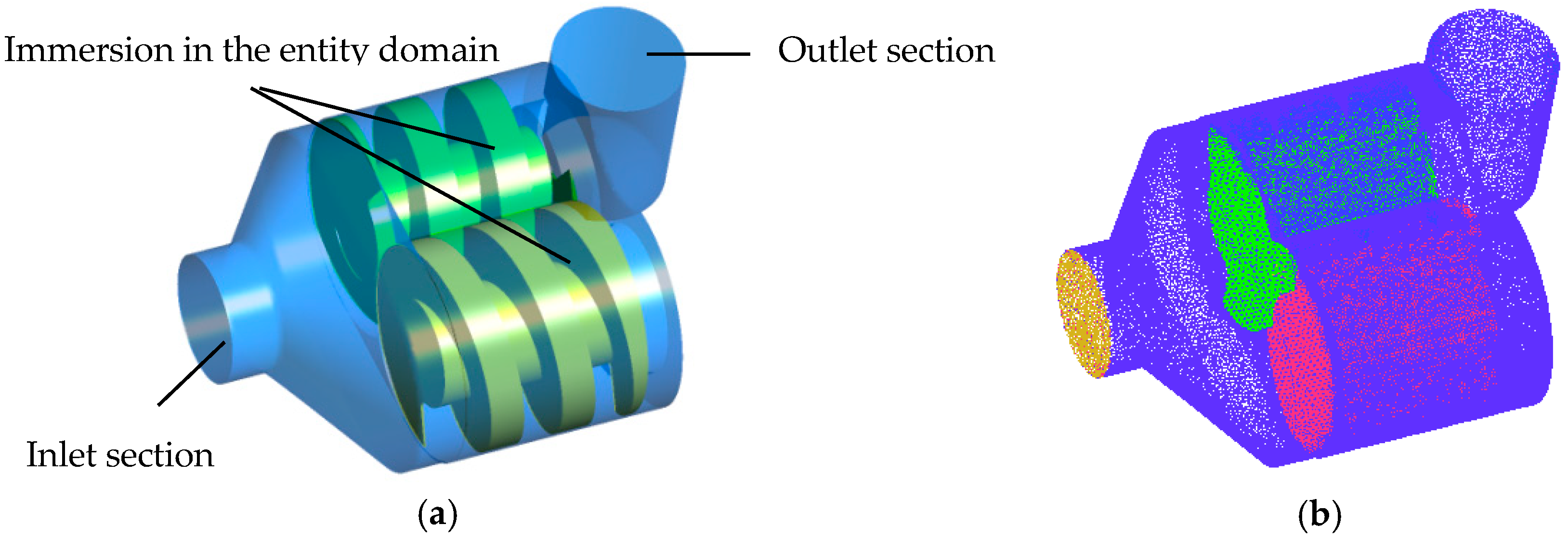
Since the working chamber volume domain is continuously modified according to each step rotor position, numerical calculation uses an immersed solid technique. An immersed solid method is a dynamic mesh method, proposed in the ANSYS CFX software, which can perform steady state or unsteady simulation with rigid solid objects immersed in the fluid field. The simulation method is mainly applied to the simulation of moving boundary problems that are difficult to solve by other methods (such as for gear pumps, screw pumps and other grids with minimal mesh movement problems). During the simulation, the CFX solver applies a momentum source to the fluid in the immersed solids area to force the fluid to move with the solids. Immersed solids are considered as source terms in the flow equation that drives fluid motion to match solid motion. In order to solve the shape of the interface immersed in solid, immersed solid surface mesh quality requirements should be relatively high, as shown by Song et al. [14,15].

3.2. Control Equations and Turbulence Model

The flow inside the double helix pump depends on the mean flow rate, the screws’ relative positions versus time and the interaction between screw rotation and the pump boundary walls. In this paper, the Reynolds time-averaged method is used to simulate the control equations of pump internal flow with a continuous equation, a three-dimensional Reynolds averaged N-S equation and a standard k-ε double equation assuming turbulent flow as performed by Song et al. [15]. For some specific working points, the k-omega SST model is also used for comparison purposes. The laminar model is also used for some working points when a low-pressure difference governs specific low values of the leakage backflows.

3.3. Meshing

UG software is used for modelling the three-dimensional calculation area of the helix pump runner and casing. Meshing in the ICEM CFD software is uesd to slove the physical method in the numerical simulation process without the fluid domain and the solid domain grid deformed, and an unstructured grid division is used. The unstructured grid of the calculation is shown in Figure 3 and Figure 4a, the total grid number is 3,862,159 and the total node number is 632,906. This number is quite comparable with what has been chosen by Yan. et al. [12,13,16], using a polyhedral mesh set-up. However, the present grid number is probably not sufficient inside the flank gaps (see the enlarged region on the left side of Figure 4a) in between the two screws. A much denser mesh is chosen inside the tip gaps (see the enlarged region on the right side of Figure 4) because about 80% of all leakage occurs in this region, as suggested by Vetter and Wincek [1].
A mesh sensitivity analysis was performed for one flow rate value (3.6 m3/h), N = 1430 rpm, with a given time step of 0.0004 s. The corresponding results are given in Table 2 and in Figure 4b for the outlet pressure value. There is a slight modification of 0.64% on the outlet pressure result in between the last two mesh numbers. It has been considered that an asymptotic value is reached for a mesh number of 3,862,159.
The boundary conditions are defined as follows:
  • The rotor is considered as an immersed solid, keeping the momentum scaling factor at 10.0.
  • The total pressure value is given at the inlet plane of the calculation domain. The pressure value levels are given relative to a standard atmospheric pressure of 101,325 Pascals.
  • A volume flow rate is imposed as the outlet boundary condition; the flow direction is perpendicular to the exit boundary.
  • The flow (water) is incompressible and at normal temperature. No heat exchange is taken into account.
  • Calculations are performed for five different flow rates with different time steps. The inlet section location is closed to the experimental pressure tap. However, for simulation, another section is also tested, much further upstream, in order to check how initial conditions may influence the local numerical results.

4. Experimental Set-Up and Results

4.1. Experimental Set-Up

The experiments were carried out at the Key Laboratory of Fluid and Power Machinery of the Ministry of Education, Xihua University. Normal-temperature water was used as the test medium. The flow rate is measured by an LDG-MIK electromagnetic flowmeter. Inlet and outlet pressures are measured by an MIK-Y109 digital pressure gauge. Rotational speed can be continuously controlled and modified. The test loop is shown in Figure 5. An electromagnetic flow meter is placed further upstream from the pump inlet. Its accuracy is ±0.5% (full scale 3.58–83.62 m3/h), the accuracy of the outlet pressure gauge is ±0.25% (full scale 0–0.6 MPa) and the accuracy of inlet pressure gauge is ±0.5% (full scale −0.1–0.1 MPa).

4.2. Experimental Results

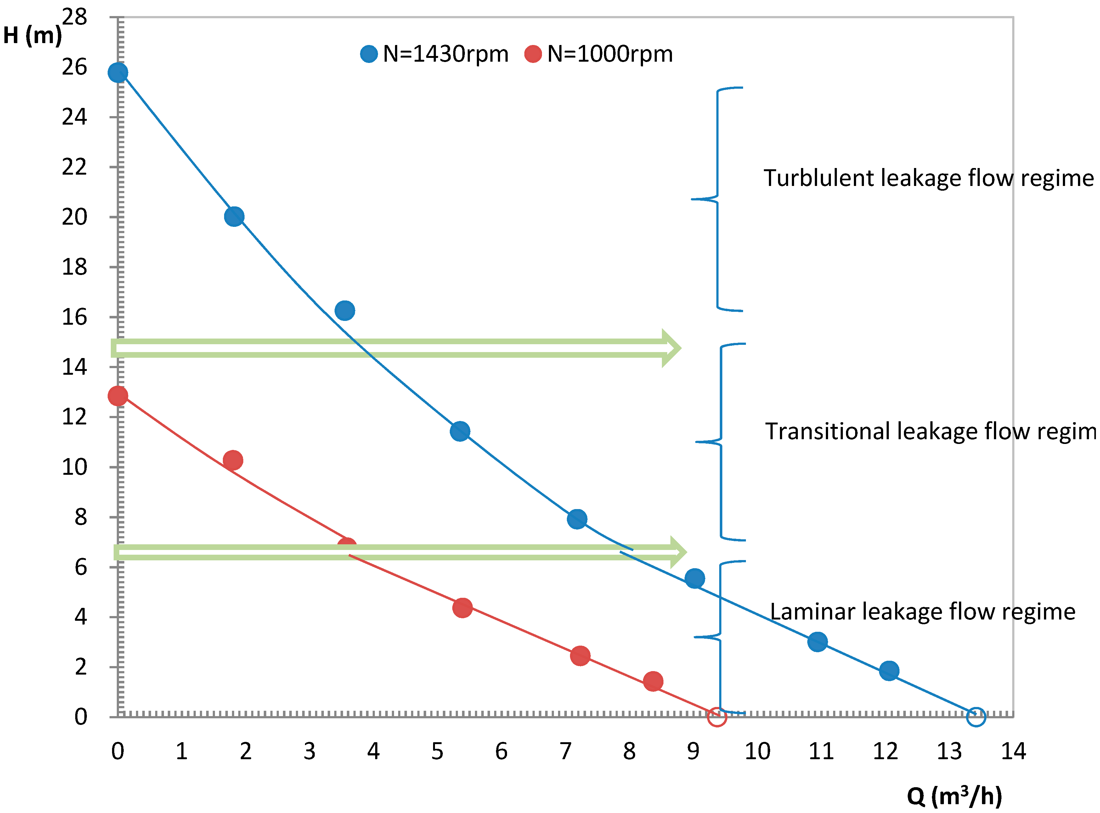
The experimental tests were carried out for several water flow rates operated with two different rotational speeds equal, respectively, to N = 1430 rpm (rated value) and N = 1000 rpm. The corresponding results are given in Figure 6. The maximum volume flow rate value can be theoretically evaluated when the pressure change between the inlet and outlet sections is equal to 0. It corresponds to the displacement volume (or swept volume), which is conveyed by the helix pump. The corresponding values, according to the relation proposed by Prang and Cooper [2], are 13.42 m3/h and 9.34 m3/h, respectively, for 1430 and 1000 rpm. These values are determined assuming no leakage between each chamber; so, they are slightly overestimated. However, they correspond well to the extrapolation from the experimental curves in Figure 6, taking experimental uncertainties into account. Compared with roto-dynamic pumps (centrifugal, mixed and axial ones), screw pump performance curves exhibit an opposite curvature. The more the pressure difference increases, the more the slip across each land increases, affecting the pump volumetric efficiency. The volumetric efficiency variation is strongly related to the leakage velocity and the local friction factor, which also depends on the local Reynolds number value. An approximate evaluation of the Reynolds number value can be done using the present experimental results. For the maximum head value, which is reached with a zero measured flow rate (when the circuit vane is closed), leaks are strongly present inside the pump land and chambers. Anticipating a turbulent flow regime, the evaluation of the maximum slip velocities gives 10 m/s and 7.25 m/s, respectively, for 1430 and 1000 rpm. These values are about 10 times larger compared with the axial screw land velocities, which are in the opposite direction to the slip (leakage) velocities. The corresponding axial slip Reynolds number values are, respectively, 1.4 × 10⁴ and 0.9 × 10⁴. These values correspond to the region from which a turbulent flow regime may occur according to the well-known Moody chart. This means that the axial Reynolds number range will probably tend to a transitional or laminal region for a decreasing pump operating head and low rotational speeds. Looking at the experimental results given in Figure 6, it can be observed that the slopes of the two performance curves are modified when the head approximately reaches a value of 8 m. For low H values, each slope value remains constant, indicating a laminar leakage flow regime. On the opposite side, for high H values and N = 1450 rpm, the curves exhibit a concave downward shape typically related to a turbulent leakage flow regime. This has already been suggested by Prang and Cooper [2]. When H is between 7 m and 14 m, a transitional zone can be detected for both rotational speeds; a rapid estimation of the leakage Reynolds number gives a value of 4 × 10³, which corresponds to a transitional regime. A rough evaluation of the three regime zones that are shown in Figure 6 also corresponds to the leakage Reynolds number values obtained using the one-dimensional relations given in Section 4.4.2.

4.3. Non-Dimensional Performance Coefficients

The maximum screw pump volume flow rate is directly proportional to the rotational speed. The experimental maximum head value was found to be related to the squared of the rotational speed. Consequently, non-dimensional coefficients are used, the definitions of which are given below [17,18,19,20]:
Flow coefficient: Φ = Q / ( 2 S × U t ) ,
Head coefficient: ψ = gH / U t 2 ,
Fluid power coefficient: χ = ρ gHQ / U t 3
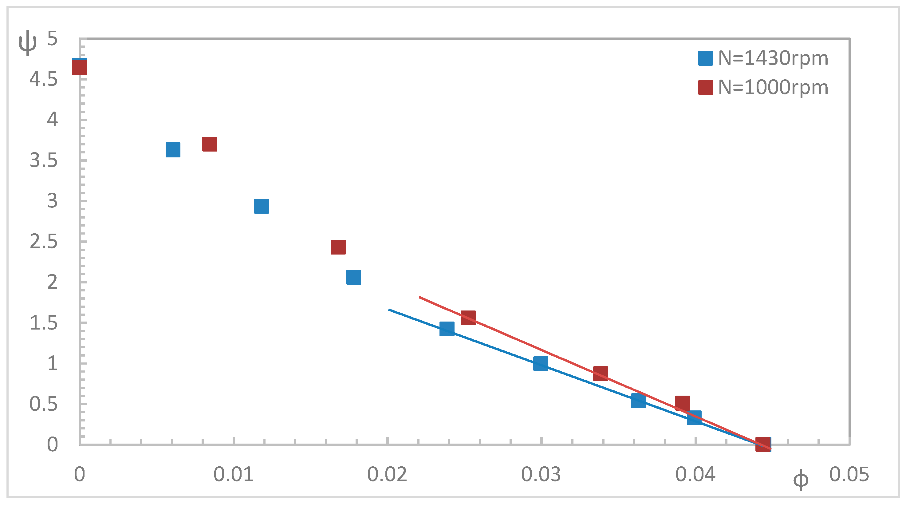
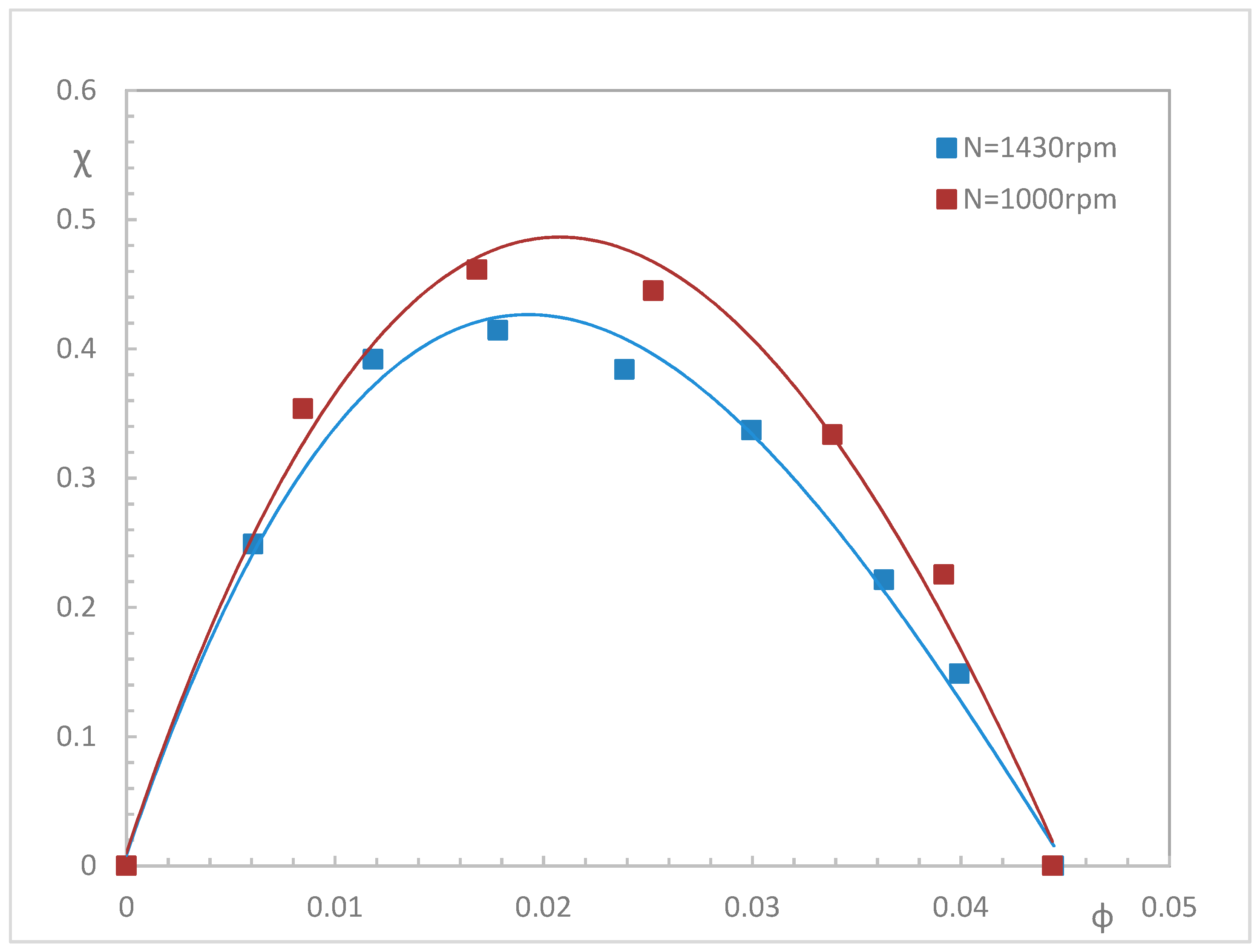
Results are shown in Figure 7 and Figure 8, respectively, for the flow head coefficient ψ and the flow power coefficient χ. Each curve depends on the rotational speed. In Figure 7, and for low head coefficient values, ψ evolutions are quasi-linear when the flow coefficient is high, as pointed out in the previous section related to a laminar leakage flow regime (see Figure 6). Figure 8 shows that χ reaches a maximum value for a specific flow coefficient value that depends on the rotational speed. The maximum value of the flow power corresponds well to the manufacturer’s instructions when low viscosity fluid is used. Finally, both non-dimensional coefficient values are higher when the rotational speed is small. This could be related to the driven main flow friction losses is low when the rotational speed is small (except for leakage flow areas).

4.4. Leakage Volume Flow Rate Evaluation

4.4.1. Experimental Leakage Calculation

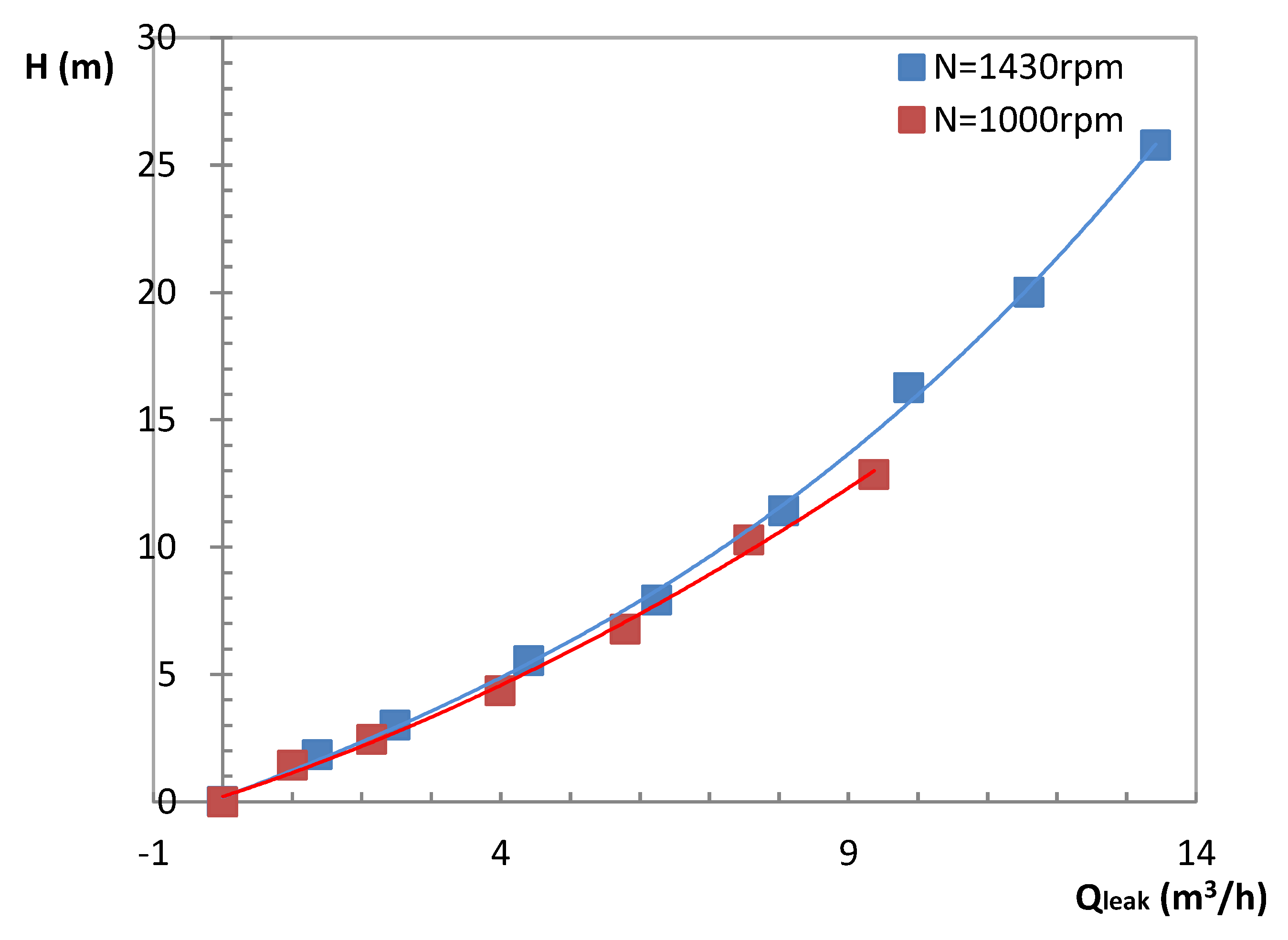
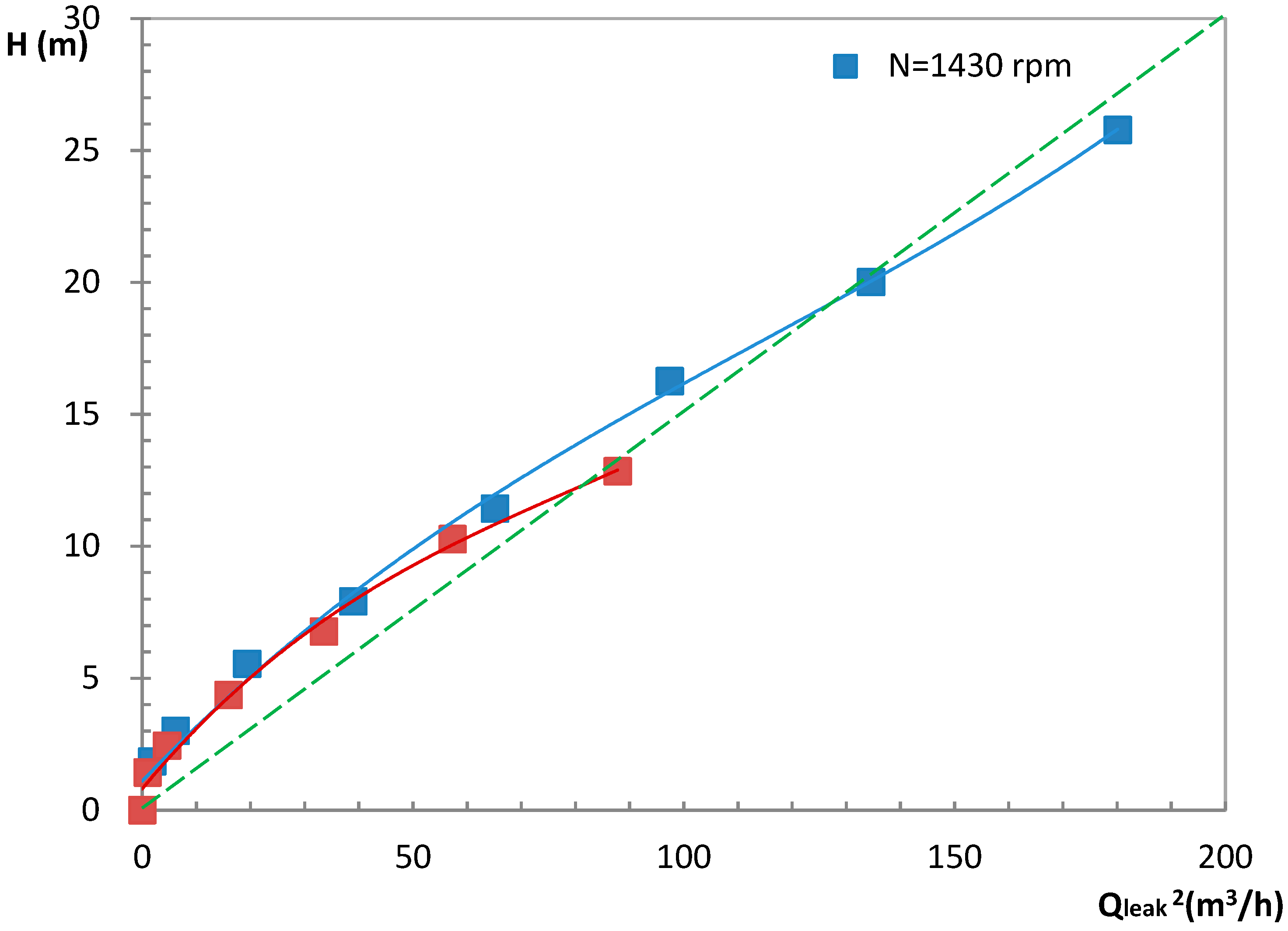
Starting from the experimental results obtained in Figure 6, it is possible to deduce the leakage flow rate amount Qleak versus head as shown in Figure 9. One single curve is then obtained. Thus the leakage amount mainly depends on the difference of pressure. Since the leakage velocity amount should be proportional to the root mean squared of the pressure difference for turbulent flow leak regime, H versus Qleak2 is plotted in Figure 10. One can observe that, for high H values (more than 13–14 m), the experimental leakage results are on a straight line, corresponding to a turbulent assumption concerning the loss coefficient that governs the leakage flow between each land. Below H = 14 m, the experimental leakage flow rate is lower than the estimated turbulent region and the friction coefficient is larger and tends to reduce the leak. The observed limiting value around H = 14 m for a turbulent regime also corresponds to the estimated one already proposed in the previous section (see Figure 6)

4.4.2. Analytical Leakage Evaluation

According to several authors [1,2,21,22,23,24,25,26], an evaluation of the flow rate leakage can be done using the following relationship:
Qleak = Vleak × Aleak = Aleak × (2 × g × Δh /(k + λ l/ dh ))0.5
  • where Δh is the difference of head in each land. Neglecting the losses at inlet and outlet pump end caps, the head difference of each land is obtained assuming the same head step value in each screw land. This is confirmed by the numerical results given in Section 6.
  • k = 1.5 (k = k1 + k2; k1 = 0.5 for a sudden acceleration and k2 = 1.0 for a sudden expansion)
  • λ = 64/Releak for a laminar flow regime
  • λ = 0.3322 × Releak−0.25 for a turbulent flow regime; Releak = Vleak × δ/υ
The related leak velocity and leakage flow rate are calculated using an iterative procedure since λ depends on the local leak velocity. Convergence is obtained within a maximum of 4 to 5 iteration steps. The results are found to be always 20% overestimated compared with the experimental leakage amount. This evaluation can be probably altered by viscous and rotational effects inside the screw main flow that have been neglected in the present approach. The evaluation of Δh is also difficult to perform because losses at the inlet and outlet pump end caps are difficult to evaluate.

5. Comparisons between Experimental Performances and CFD Results

5.1. Numerical Set-Up Conditions

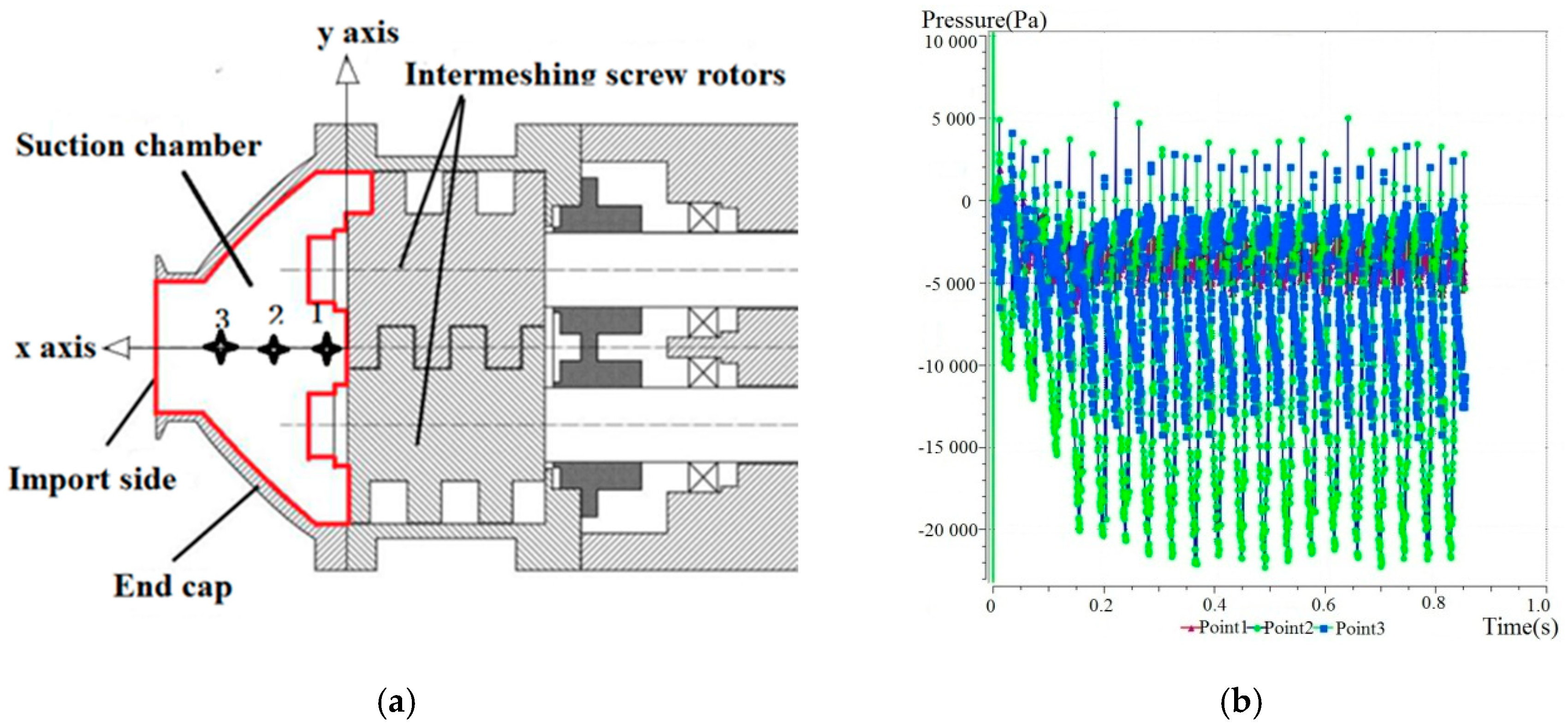
(a) Three selected points, located at the inlet section of the twin screws (see Figure 11a), are used to record local calculated wall static pressure with time. The results are given in Figure 11b for points 1,2 and 3, which are aligned with the pump inlet axis. Periodic and stable results are obtained after eight complete screw revolutions, corresponding to 0.3356 s. Wall static pressure negative values correspond to relative pressure values compared to a reference pressure set at zero. The corresponding lowest absolute pressure values are close to 101,325 − 22,000 = 79,325 Pascals.
(b) Upstream boundary location effects on numerical results.
In order to evaluate the influence of the inlet condition location, two different inlet tube lengths are modelled at 0.5 d (which corresponds to the actual size) and a longer one of 6.5 d, which is a fictitious one. All results (not presented here, for simplification) do not depend on the location of the inlet plane and specifically the instantaneous variation of local pressure and velocity that are discussed in the next section. In addition, no damping phenomena have been detected because of a longer inlet tube. This is probably due to the inlet boundary condition being only pressure combined with an outlet condition for which flow rate is imposed.

5.2. Overall Pump Performances

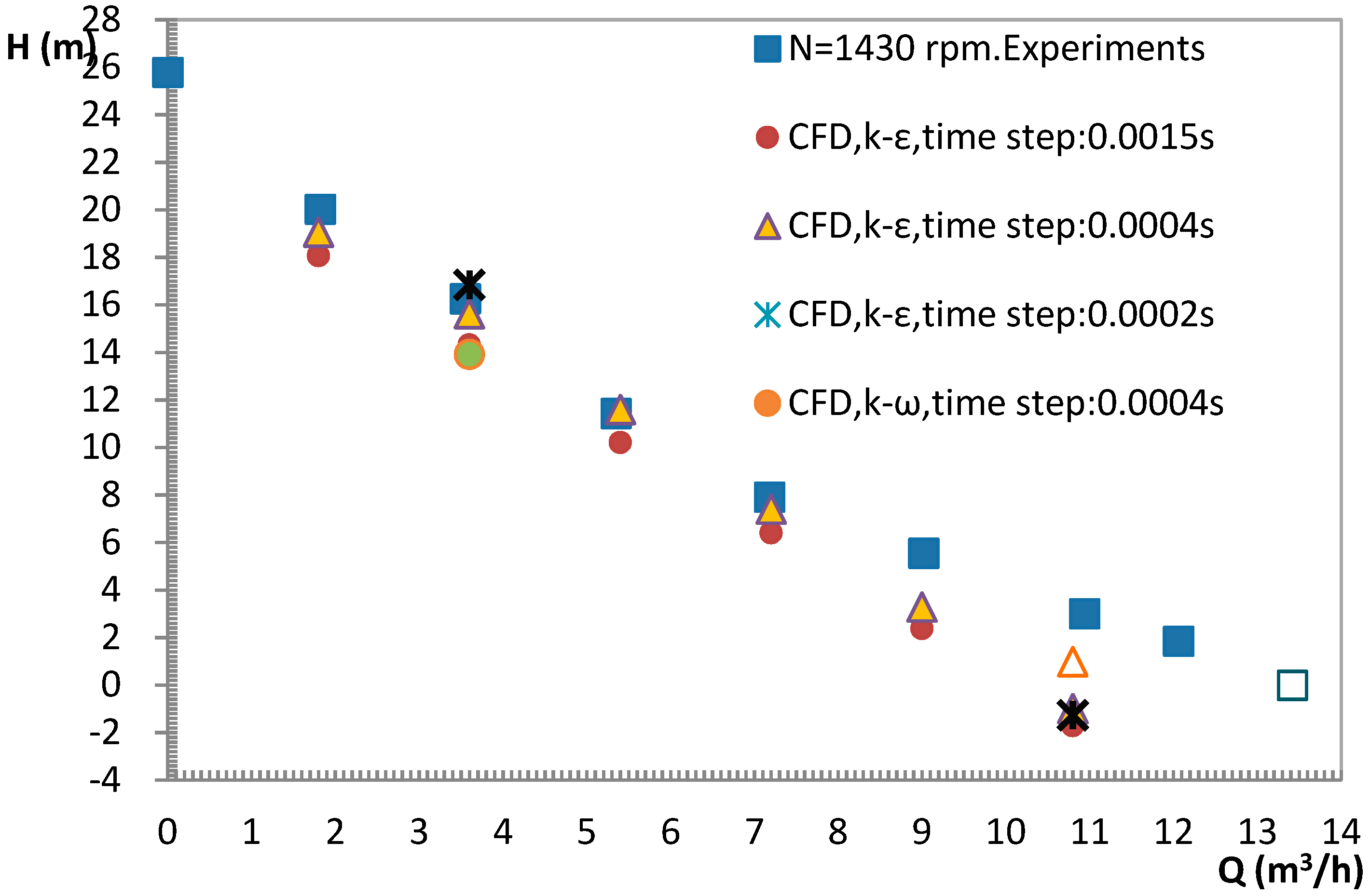
As shown in Figure 11 for N = 1430 rpm, CFD results are always lower compared with experimental ones when the time step between two successive screw rotary positions is too big (initially set at 0.0045 s). The difference between experimental and calculation results is, however, less than 5% for flow rate values between 0 and 6 m3/h, for which a turbulent leakage flow regime is supposed. This can be considered to meet the engineering purpose which indicates that such numerical simulation results may be considered for relative comparisons. CFD results assuming a laminar regime were also performed for a large flow rate value of 10.8 m3/h. Much better results are obtained closer to the experimental ones (see Figure 12).
In order to evaluate the influence of time step on the CFD results, two additional values are tested, 0.0004 s and 0.0002 s, corresponding, respectively, to four times and eight times lower than the initial one. The results are given in Figure 12. The smaller the time step, the closer the calculated pressures compared with the experimental ones inside the turbulent flow regime zone. This is typically the case when a time step of 0.0002 s is applied, for example, at N = 1430 rpm (this time step of 0.0002 s is set for only two different flow rates for comparison). Note that a time step of 0.0004 s corresponds to a rotor angular rotation of 3.43 degrees for 1430 rpm.
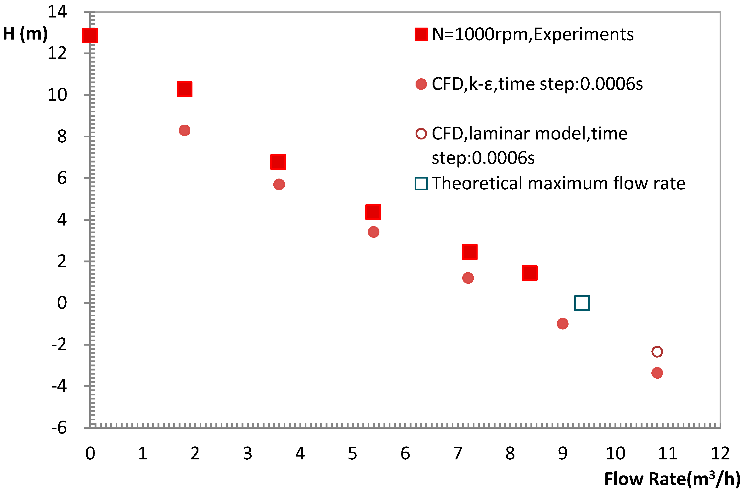
For N = 1000 rpm, a time step of 0.0006 s is chosen in order to keep the same angular rotation of 3.43 degrees. The corresponding comparison is given in Figure 13. The same kind of results are observed: CFD results always underestimated the delivered pump flow rate for a given head coefficient value when a turbulent model is used. Thus, in the specific zone of a laminar regime (most of the experimental results obtained for N = 1000 rpm are inside this zone), CFD results at a high flow rate, using a laminar flow model, give quite better results, as shown in Figure 13. It is believed that a laminar model will be suitable for the whole performance prediction for this rotational speed.

6. Local Results from CFD and Analysis

Since the solid boundary varies with time as the helix pump rotates, the instantaneous flow field over a series of phases is used to represent flow features for an entire time period. The following analysis is based on the result for a mass flow value of 3.6 m3/h.

6.1. Pressure Distribution

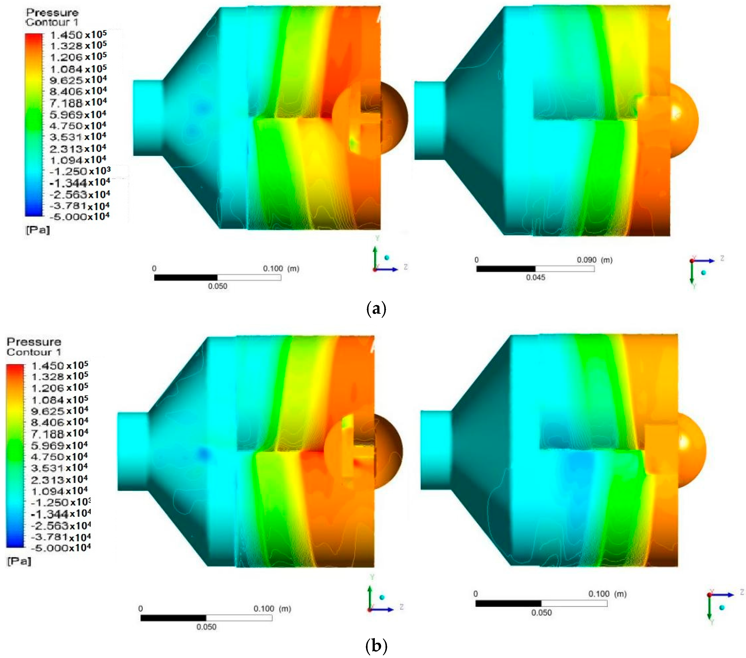
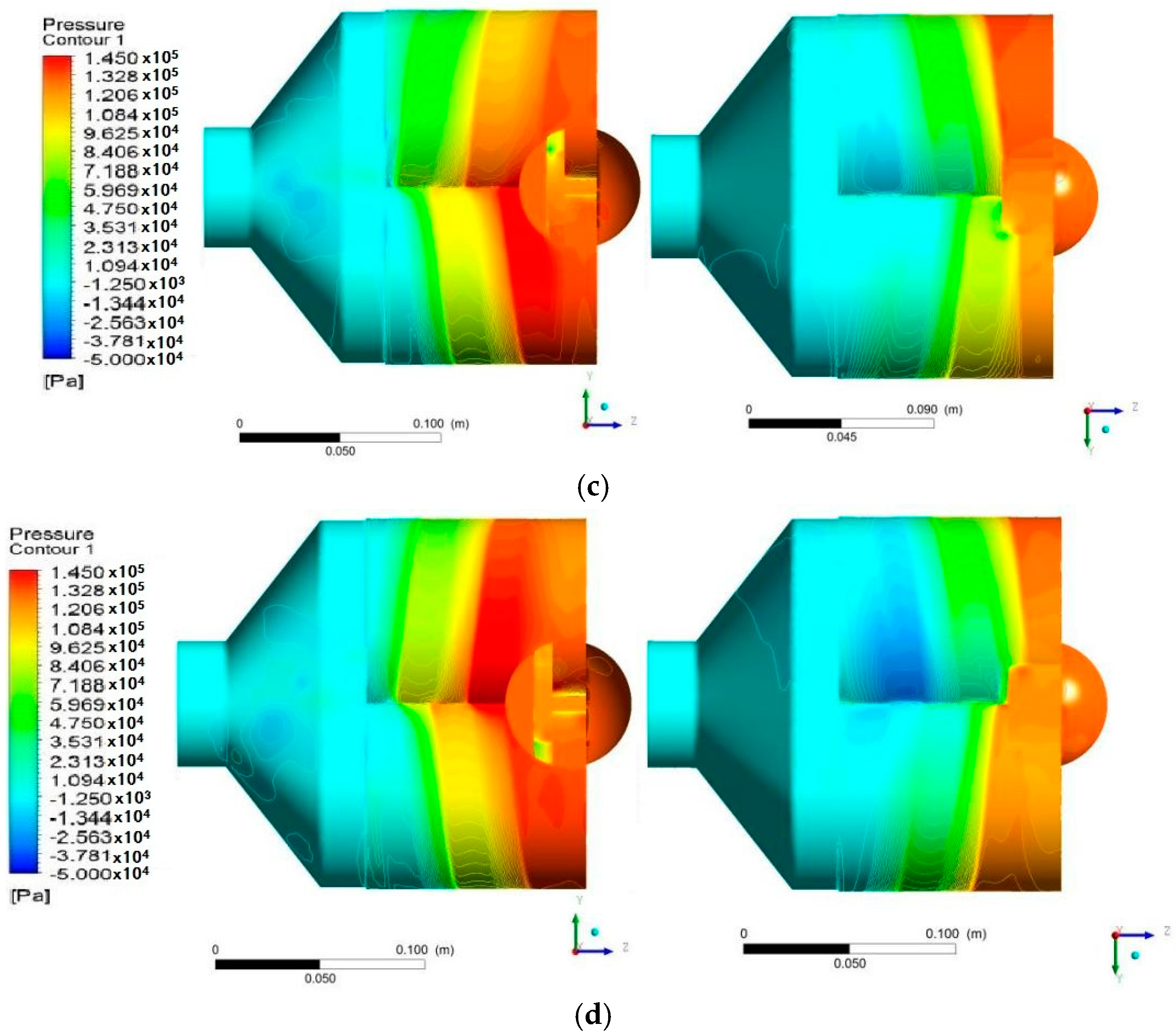
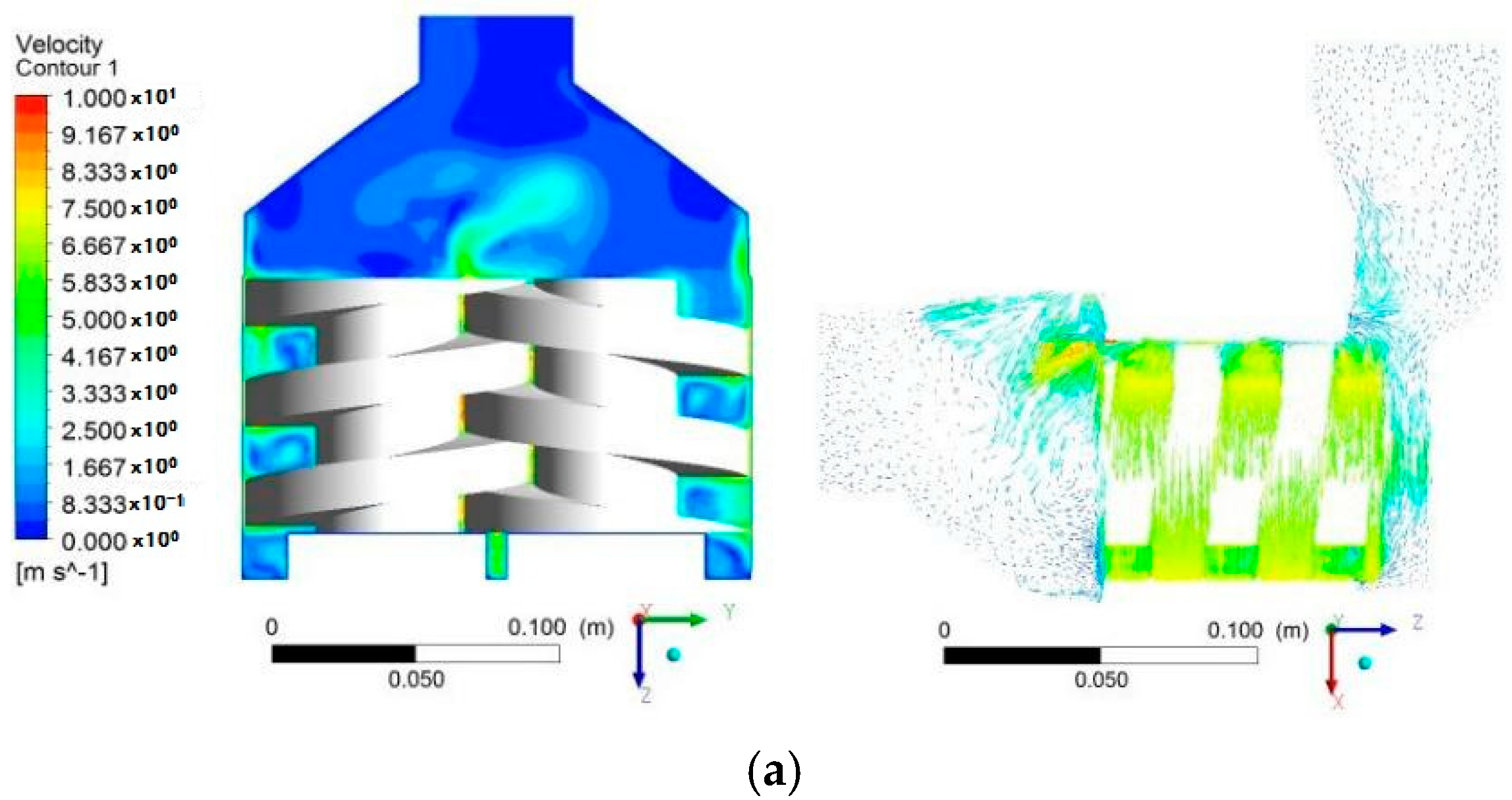
Four instantaneous instants corresponding to equal intervals of 90° steps are chosen to represent parts of the entire time period change in the flow boundary at 1/4T, 2/4T, 3/4T, 1T, where T is the time for one rotation cycle. The pressure distributions are shown in Figure 14. The right and left parts of Figure 14 correspond, respectively, to the top view and the upward view. Velocity fields are also shown in Figure 15 for the four different time steps previously defined.
It can be seen in Figure 14a–d that the mean pressure gradually increases step by step along the axial direction from the inlet to the outlet, indicating that the helical rotor is the main pressurizing part with the supercharging effect and the maximum pressure at 195,300 Pa. Negative relative pressure can be observed upstream from the rotor inlet with an instantaneous value of approximatively −22,000 Pa, which is mainly due to the reverse leakage velocity of the helix pump close to the inlet land section; this value corresponds the dynamic pressure related to a local leak velocity value around 7 m/s. During one rotation, there are alternating low pressure zones between the two rotor intermeshing zones. The high-pressure zone at the exit side also simultaneously alternates between the two rotors. It can be seen from Figure 9 that the overall pressure varies with time, indicating that the pressure variation is well related to the process of transporting liquid from inlet to outlet. The main of the high-pressure and low-pressure zones is so related to the rotor area modification that it allows flow transfer.

6.2. Velocity Distribution

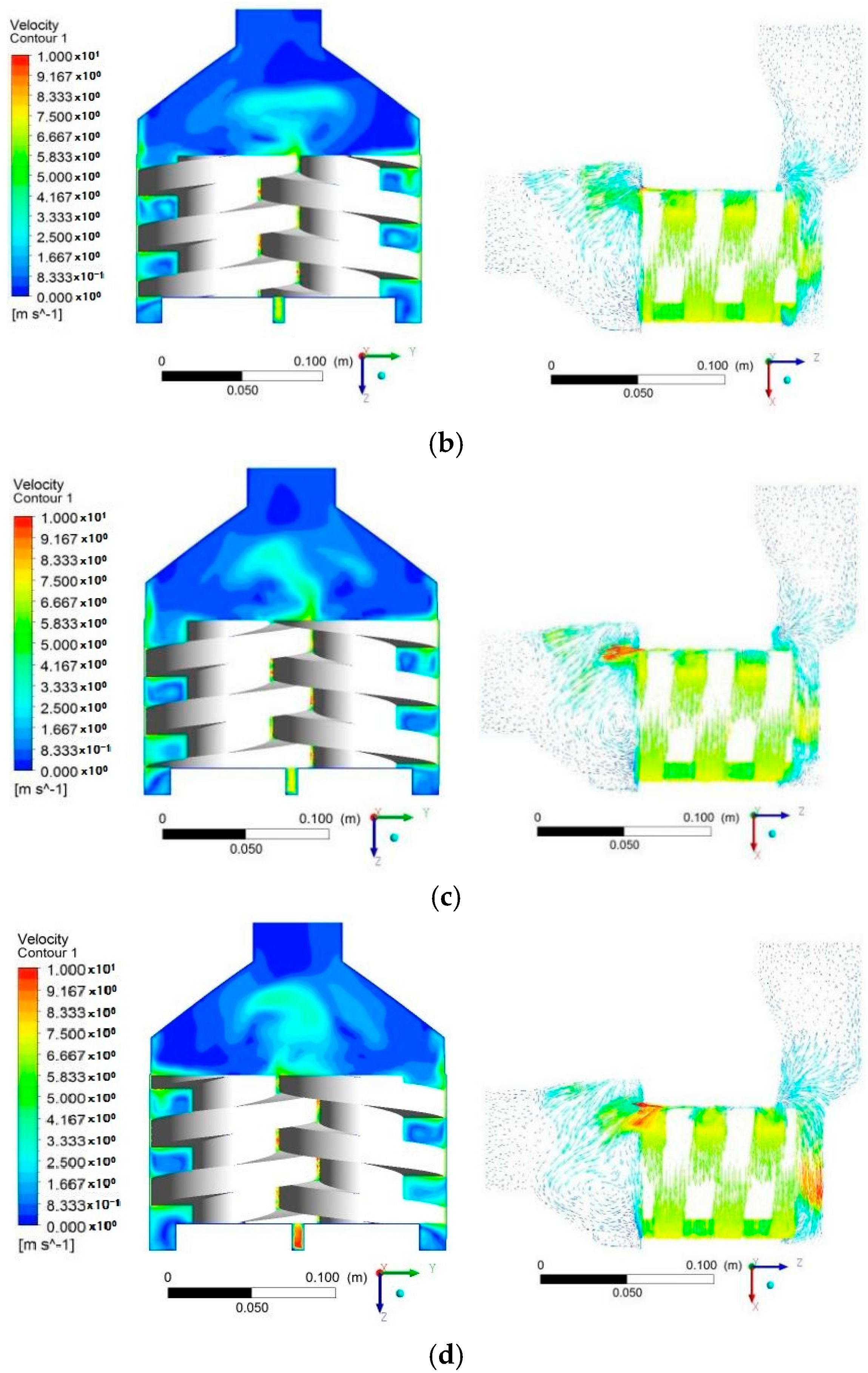
Figure 15a–d shows the velocity contours and vectors in a specific radial cross-section of the pump. After entering the rotor intermeshing region, local velocities can reach high values related to high rotational speed. Some negative axial velocity regions can be observed (reaching 10 m/s), directing towards the inlet pipe section, located close to the gap between the helix addendum circle and the lining inner bores, that corresponds to the main leakage areas. High velocity distortions also exist at the exit end of the pump. A local specific analysis on velocity fields in some additional locations is given in the following section.

6.3. Particular Velocity Fields

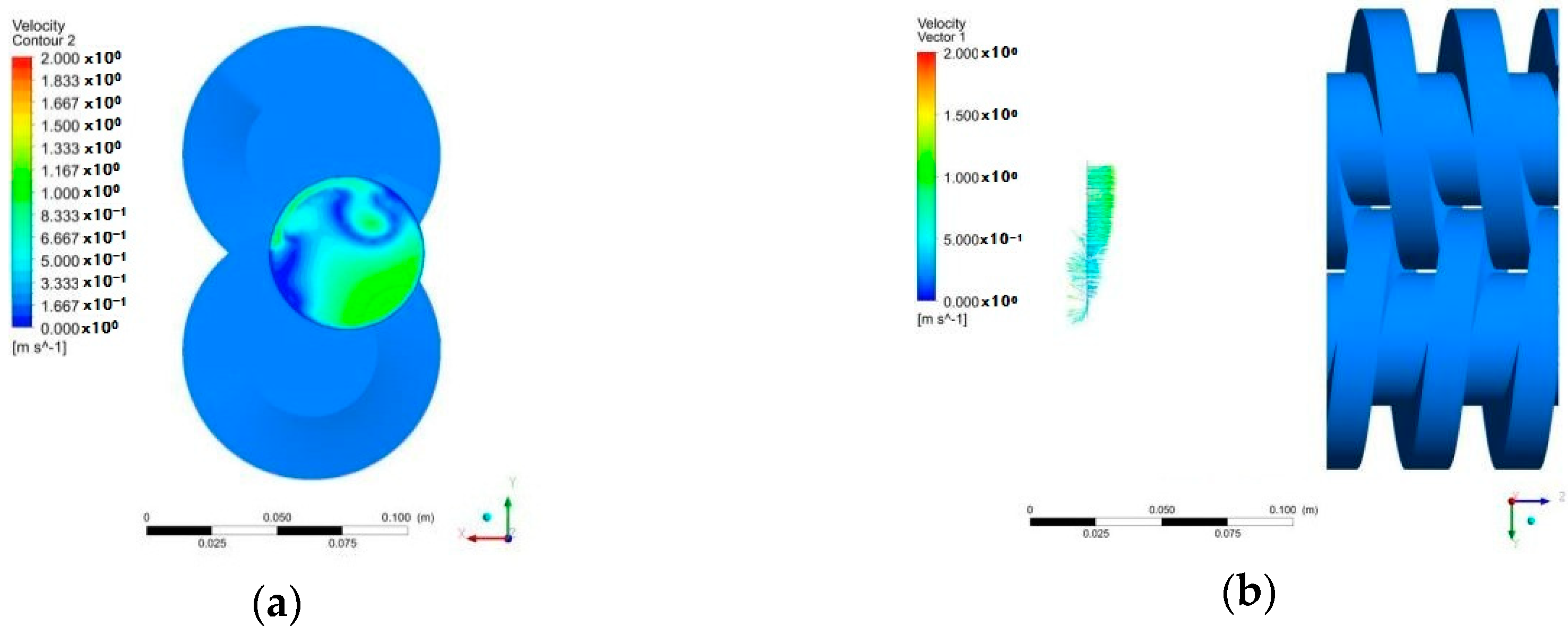
This section focuses on the instantaneous velocity and pressure fields in the inlet pump plane (Figure 16), the intermediate plane located just in front of the rotating parts (Figure 17) and the outlet plane (Figure 18). In Figure 16, one can observe that the inlet section center’s diameter is not located in the mid plane corresponding to the rotor’s rotation axis. This position faces the inlet location for which the two screws capture the flow in the entering meshing system. This asymmetry is responsible for high velocity gradients with some negative leakage velocities that have already been seen in Figure 15. The combination of the inlet chamber size creates strong flow distortions that are transported upstream in the inlet plane. These velocity distortions also depend on time due to the screw combined rotation.
In Figure 18, pressure and velocity gradients still exist at the outlet pump plane, but with lower values compared with the two previous inlet sections. A symmetry plane can be detected, corresponding to y = 0, that is the symmetry plane of the whole pump.
These numerical results will be used to establish more suitable loss coefficients in order to calibrate and upgrade the analytical model presented in Section 4.4.

7. Conclusions

In this paper, an immersed solid method coupled with CFD simulations was used to simulate the internal flow field of a double helix pump. The analysis between numerical calculation and experimental results comes to the following conclusions:
(1)
Overall performance measurements were performed in a twin screw pump for two rotational speeds, using water as the working fluid. As expected, the leakage amount was found to be independent of the rotational speed and only depends on the pressure difference.
(2)
Physical analysis allows the determination of laminar, transitional and turbulent leakage flow regimes that govern the leakage amount in such pump geometry.
(3)
Analytical evaluation based on loss friction models always overestimated leakage values compared with experimental ones. The empirical loss coefficient must be re-evaluated according to rotational effects and viscous forces that have been neglected in the present study.
(4)
CFD simulation results generally show better results compared with analytical ones. The pressure gradient in the rotor meshing area is related to the displaced volume with time.
(5)
In order to obtain suitable numerical outlet pressure delivery values, three rotating time steps were tested. A time step value corresponding to an angular rotor variation of at least three degrees was sufficient enough to reach experimental results within an error of less than 2%. In the same respect, stable periodic results were obtained for a minimum of six complete screw revolutions.
(6)
The main leakage areas correspond to the casing gap between the rotor and the pump casing. The results on leakage values strongly depend on a correct evaluation of the laminar and turbulent flow regime that depends on the local pressure differences.
(7)
The inlet flow before the screw inlet plane is highly non-uniform. This is related to the squeezing effect of the two rotors and the large local amount of leakage flows from the casing gap.

Author Contributions

Conceptualization, W.Z.; methodology, W.Z.; software, W.Z. and S.Y.; validation, G.B., Q.J. and H.L.; formal analysis, W.Z. and G.B.; investigation, W.Z.; resources, W.Z. and Q.J.; data curation, W.Z.; writing—original draft preparation, S.Y.; writing—review and editing, G.B. and X.L.; visualization, Y.H.; supervision, Q.J.; project administration, W.Z.; funding acquisition, W.Z.

Funding

This research was funded by the National Key R&D Program of China, grant number 2018YFB090520; the National Natural Science Foundation of China, grant number 51769035; the Open Research Subject of Key Laboratory (Fluid Machinery and Engineering Research Base) of Sichuan Province, grant number szjj2016-002; the Sichuan Province Education Department Research Item “Research of Two-Phase Flow Characteristics of Double Helix Pump”, grant number 18ZB0563.

Conflicts of Interest

The funders had no role in the design of the study; in the collection, analysis, or interpretation of data; in the writing of the manuscript; or in the decision to publish the results.

Nomenclature

dhhydraulic diameter (meters (m))
gacceleration (meters per second squared (m/s−2))
Hglobal pump head(meters of water (m))
k loss coefficient (-)
Qvolume flow rate(meters cubed (m3) per hour (h))
ReleakReynolds number based on leak tip gap and leak velocity Vleak(-)
Sfront section of the one screw land(meters squared (m2))
Uttip speed screw rotational velocity(meters per second (m/s))
Vvelocity(meters per second (m/s))
δtip radial gap (meters (m))
Δhhead value between each land (meters of water (m))
Φflow coefficient (-)
λfriction loss coefficient (-)
Ψhead coefficient (-)
ρflow density (kilograms per meter cubed (kg/m3))
χfluid power coefficient (-)
Ωsspecific speed Ωs = ω × Q0.5/(g × H)3/4 (-)
Subscripts
leakrelated to the leak

References

  1. Vetter, G.; Wincek, M. Performance Prediction of Twin-Screw Pumps for Two-Phase Gas/Liquid Flow. In Proceedings of the Fluid Engineering Conference (FED); Pumping Machinery; ASME: Washington, DC, USA, 1993; Volume 154, pp. 331–340. [Google Scholar]
  2. Prang, A.J.; Cooper, P. Enhanced Multiphase Flow Predictions in Twin-Screw Pumps. In Proceedings of the Twenty-First International Pump Users Symposium; Turbomachinery Lab., Texas A&M University: College Station, TX, USA, 2004. [Google Scholar]
  3. Liu, P.; Patil, A.; Morrisson, G. Multiphase Flow Performance Prediction Model for Twin-Screw Pump. ASME J. Fluid Eng. 2018, 140, 031103. [Google Scholar] [CrossRef]
  4. Wang, C.L.; Xing, Y.; Ruan, J.S. Experimental study on screw groove of labyrinth screw pump. Pump Technol. 2006, 2, 18–20. [Google Scholar]
  5. Li, F.T. Screw Pump; Machinery Industry Press: Chengdu, China, 2010; Volume 3, pp. 147–171. [Google Scholar]
  6. Mao, H.Y.; Li, N.; Yang, B.; Zhang, J. Forming of the rotor tooth profile of cycloid rotor pump. Shandong Sci. 2003, 16, 26–29. [Google Scholar]
  7. Ryazantsev, V.M. Characteristics of screw pumps with screws of different profile. Chem. Pet. Eng. 1998, 34, 109–113. [Google Scholar] [CrossRef]
  8. Zhang, Y.; Tang, Q.; Li, Z.; Yan, D. Leakage Mechanism of Screw Pump Based on Leakage Model in Fluid Mechanics. J. Agric. Mech. 2014, 45, 326–332. [Google Scholar]
  9. Tian, G.W.; Zhang, Y.C.; Li, J.Z. Computational fluid dynamics (CFD) simulation of the internal flow in a labyrinth screw pump. J. Beijing Univ. Chem. Technol. (Nat. Sci. Ed.) 2007, 34, 208–220. [Google Scholar]
  10. Wang, C.L.; Ma, Q.Y.; Xing, Y.; Li, T.T.; Yang, M. Numerical simulation and perform ance prediction inside trapeziform labyrinth screw pump. J. Jiangsu Univ. (Nat. Sci. Ed.) 2008, 2, 138–142. [Google Scholar]
  11. Tang, Q.; Zhang, Y.; Gao, Z. Numerical Simulation of Flow Field Dynamics Characteristics for Twin-screw Pump. China Mech. Eng. 2010, 21, 1453–1457. [Google Scholar]
  12. Yan, D.; Kovacevic, A.; Rane, S. Rotor Profile Design and Numerical Analysis of 2-3 Type Multiphase Twin-Screw Pumps. Proc. Inst. Mech. Eng. Part E J. Process Mech. Eng. 2018, 232, 186–202. [Google Scholar] [CrossRef]
  13. Yan, D.; Kovacevic, A.; Rane, S. Numerical Investigation of cavitation in Twin Screw Pumps. Proc. Inst. Mech. Eng. Part C J. Mech. Eng. Sci. 2018, 232, 3733–3750. [Google Scholar] [CrossRef]
  14. Song, X.G.; Jung, J.H.; Lee, H.S.; Kim, D.K.; Park, Y.C. 2-D Dynamic Analysis of a Pressure Relief Valve by CFD. In Proceedings of the 9th Wseas International Conference on Applied Computer and Applied Computational Science, Hangzhou, China, 11–13 April 2010; pp. 136–140. [Google Scholar]
  15. Song, X.G.; Park, Y.C.; Park, J.H. Blowdown Prediction of a Conventional Pressure Relief Valve with a Simplified Dynamic Model. Math. Comput. Model. 2013, 57, 279–288. [Google Scholar] [CrossRef]
  16. ANSYS Inc. Release 15.0 Documentation for ANSYS; ANSYS Inc.: Canonsburg, PA, USA, 2015. [Google Scholar]
  17. Xie, L.H.; Zhao, X.Y.; Zhang, J.M. ANSYS CFX Fluid Analysis and Simulation; Beijing Electronics Industry Press: Beijing, China, 2010. [Google Scholar]
  18. Fan, Y.L.; Zhang, J.W.; Hu, C.Y.; Li, S.X. Influences of Structural Parameters on Properties of Poppet Valves. China Mech. Eng. 2017, 28, 1714–1717. [Google Scholar]
  19. Chen, S.S.; Ge, Q.; Zhou, Z.F.; Yang, G.P.; Yan, D.F. Numerical simulation of three-dimensional turbulent flow for reversible intake passage in large pumping stations. J. Jiangsu Univ. (Nat. Sci. Ed.) 2005, 2, 102–105. [Google Scholar]
  20. Chen, S.S.; Zhou, Z.F.; Qu, L.F.; Yang, G.P.; Yan, D.F. Numerical simulation of three-dimensional turbulent flow for tank-style outle tpassage in large pumping stations. J. Jiangsu Univ. (Nat. Sci. Ed.) 2005, 6, 468–471. [Google Scholar]
  21. Hu, K.; Li, Z.B. ANSYS ICEM CFD Detailed Project Examples; Beijing People’s Posts and Telecommunications Press: Beijing, China, 2014. [Google Scholar]
  22. Jing, K. Numerical simulation of 3-D flow characteristics in twin screw extruders with combined screws. Mech. Des. Manuf. 2008, 5, 85–87. [Google Scholar]
  23. Berand, F.; Tanguy, P.A.; Thibault, F. A Three dimension Fictitious Domain Method for Incompressible Fluid Flow Problems. Int. J. Numer. Methods Fluids 1997, 25, 719–736. [Google Scholar] [CrossRef]
  24. Cao, F.; Peng, Y.; Xing, Z.; Shu, P. Thermo dynamic Performance Simulation of a Twin-screw Multiphase Pump. Proc. Inst. Mech. Eng. 2001, 215, 157–163. [Google Scholar]
  25. Tang, Q.; Misganaw, A.; Ye, X.Z.; Zhang, Y.X. Numerical anslysis for twin screw pump internal flow. Appl. Mech. Mater. 2012, 130–134, 3658–3663. [Google Scholar]
  26. Turhan, Y. Efficiency and Leakage Analysis of a Twin Screw Multiphase Pump. Ph.D. Thesis, Texas A&M University, University Town, TX, USA, 2014. [Google Scholar]
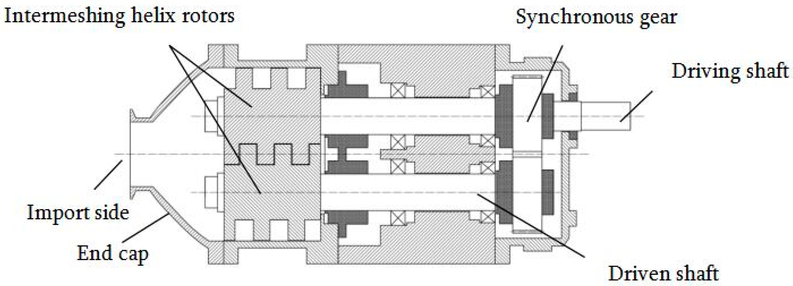
Figure 1. Schematic view of the double screw pump.
Energies 12 03420 g001
Figure 2. Screw pump rotor main parameters and the view of both screws (right side photography). See also Table 1.
Energies 12 03420 g002
Figure 3. Three-dimensional model and grid of the calculation domain. (a) Three-dimensional modelling; (b) grid-generated graph.
Energies 12 03420 g003
Figure 4. Grid map analysis of pump. (a) Local grid map of pump closed to the gaps; (b) mesh sensitivity curve.
Energies 12 03420 g004
Figure 5. Double screw pump test loop. (a) Real test loop; (b) Schematic diagram.
Energies 12 03420 g005
Figure 6. Experimental overall pump performance chart for two rotational speeds.
Energies 12 03420 g006
Figure 7. Experimental head versus flow coefficients for two rotational speeds. The two straight lines correspond to laminar leak regime zone.
Energies 12 03420 g007
Figure 8. Experimental fluid power versus flow coefficients for two rotational speeds.
Energies 12 03420 g008
Figure 9. Deduced experimental flow leakage values versus head for two rotational speeds.
Energies 12 03420 g009
Figure 10. Comparison between experimental leakage values. The dashed straight green line, H = f (Qleak2), corresponds to a theoretical law evolution based on turbulent flow regime assumption.
Energies 12 03420 g010
Figure 11. Pressure fluctuations on selected monitoring points for N = 1430 rpm. Total time: 0.86 s. (a) Selected monitoring point locations; (b) static pressure fluctuations at 3.6 m3/h.
Energies 12 03420 g011
Figure 12. Comparisons between experimental and CFD results. N = 1430 rpm.
Energies 12 03420 g012
Figure 13. Comparisons between experimental and CFD results. N = 1000 rpm.
Energies 12 03420 g013
Figure 14. Surface pressure distribution of pump. (a) 1/4T cycle pressure distribution; (b) 1/2T cycle pressure distribution; (c) 3/4T cycle pressure distribution; (d) 1T cycle pressure distribution.
Energies 12 03420 g014aEnergies 12 03420 g014b
Figure 15. Local velocity distribution. (a) 1/4T cycle velocity distribution; (b) 1/2T cycle velocity distribution; (c) 3/4T cycle velocity distribution; (d) 1T cycle velocity distribution.
Energies 12 03420 g015aEnergies 12 03420 g015b
Figure 16. Velocity distribution of the inlet plane. (a) Velocity module field projected on the inlet plane; (b) axial velocity distribution. Negative values correspond to velocity direction opposite to the z direction.
Energies 12 03420 g016
Figure 17. Velocity distribution of the intermediate plane. (a) Velocity module field projected on the intermediate section; (b) axial velocity distribution. Negative values correspond to velocity direction opposite to the z direction.
Energies 12 03420 g017
Figure 18. Velocity and pressure distribution in the outlet plane. (a) Radial velocity distribution in the outlet section; (b) outlet section pressure distribution.
Energies 12 03420 g018
Table 1. The pump’s main dimensions.
NameValueUnits
chamber’s depth 24mm
chamber’s width 18.2mm
tip radial gap between the screw land and pump housing1.15mm
screw tooth width16.4mm
flank clearance gap between active and passive screw teeth0.9mm
screw rotor length (axial extend)88mm
screw revolution number2.54circle
pitch of the screw34.6mm
screw tip diameter99mm
screw hub diameter 51mm
pipe diameter at pump inlet section63mm
pipe diameter at pump outlet section63mm
distance between two rotors axis75.9mm
Table 2. Mesh sensitivity analysis.
Grid NumberOutlet Pressure (m)
1,621,78413.63
2,109,872 13.76
2,915,48213.91
3,862,15914.00