Article

Intake Air Mass Observer Design Based on Extended Kalman Filter for Air-Fuel Ratio Control on SI Engine

School of Automation, Wuhan University of Technology, Wuhan 430070, China
*
Authors to whom correspondence should be addressed.
Energies 2019, 12(18), 3444; https://doi.org/10.3390/en12183444
Submission received: 13 August 2019 / Revised: 3 September 2019 / Accepted: 3 September 2019 / Published: 6 September 2019

Abstract

:
Air-fuel ratio (AFR) control is important for the exhaust emission reduction while using the three-way catalytic converter in the spark ignition (SI) engine. However, the transient cylinder air mass is unable to acquire by sensors directly and it may limit the accuracy of AFR control. The complex engine dynamics and working conditions make the intake air estimation a challenge work. In this paper, a novelty design of intake air observer is investigated for the port-injected SI engine. The intake air dynamical modeling and the parameter fitting have been carried out in detail. Extended Kalman Filter (EKF) has been used to optimize the instantaneous cylinder charge estimation and minimize the effort of pump gas fluctuation, random noise, and measurement noise. The experiment validation has been conducted to verify the effectiveness of the proposed method.

1. Introduction

The spark ignition (SI) engine emission is reduced by using the three-way catalytic converter (TWC) based on electronic fuel injection control to meet the strict emission requirements. However, the conversion efficiency of TWC depends on the engine air-fuel ratio (AFR) significantly. The maximum converter efficiency and fuel economy could be guaranteed by regulating the AFR at a very narrow band around the stoichiometric value. One of the important practical aspects for the accurate AFR control is the correct intake air mass estimation in the engine cylinder [1]. However, the transient cylinder air mass is difficult to measure by sensors, due to the intake manifold dynamics.
Practically, there are two kinds of method for the intake air measurement on production engines. Using the mass air flow (MAF) sensor that was installed before the throttle can directly measure the mass flow entering the intake system, but the result has a tremendous error against the actual cylinder air mass under the transient state. The other method is using the manifold air pressure (MAP) sensor to calculate the cylinder air mass based on the speed-density approach, which is widely used on the existing engine control system, has a faster response time, and costs less. Both of the technical methods mentioned above could not directly acquire the instant cylinder air mass. In addition, the complex engine working conditions and tremendous measurement noise make the cylinder air mass estimation a challenging task and have captured enormous attention recently.
On the production engine management system, the intake air mass estimation is based on the well-calibrated look-up tables at different engine operating states. However, the dramatic change of intake dynamics and parameter varying makes a challenging problem for the traditional air estimation. Many approaches have been proposed in the literature on the air charge estimation to improve the accuracy at both the transient and steady state [2,3]. Hendricks [4] has emphasized that the pressure transducer response time existed and it was impossible to follow rather slow throttle angle transients and proposed the necessary of intake air observer to eliminate the sensor response characteristic. An adaptive observer is proposed to estimate the intake oxygen concentration of a lean-burn engine while using existing sensors with minimum computational load [5]. The research [6] proposed an air mass flow estimator design with model bias correction for a turbocharged diesel engine by off-line calculation. An in-cylinder air mass observer was implemented in [7], which combined the feedforward neural static model and a linear parameter varying (LPV) polytopic observer. Some air charge observers have been reported in [8,9] on the SI engine and the experimental results showed that the input estimation techniques could enhance the control performance. Using the Kalman filters to develop the intake air mass observer have been reported an effective way to solve the problem, as it is difficult to obtain measurements in time for the accurate cylinder air mass flow [6,10,11]. Although there was some work about the engine air charge, the complex intake air dynamics and accurate AFR control demand still aroused interest for the research of accurate intake air estimation.
In this paper, a novelty design of detailed air charge estimation observer is investigated for the port-injected SI engine. The intake air dynamical modeling and the parameter fitting have been carried out. Extended Kalman Filter (EKF) has been used to optimize the instantaneous cylinder intake air estimation. Furthermore, the experimental validation invested the effectiveness of the proposed intake air mass observer design method.

2. Air Path Modelling of the SI Engine

2.1. System Description of the Engine Air Path

For the port injected SI engine, Figure 1 shows a brief structure of the entire system. The SI engine is controlled, followed by the throttle movement and the position angle ( α ) affects the relative air mass supply. At different engine operation conditions, the intake air passes through the throttle and goes into the cylinder during the inlet valves opening. The electronic control unit (ECU) calculates and controls the fuel injection amount ( m ˙ f c m d ) based on the intake air mass and AFR control strategy. The air and injected fuel mix in the intake manifold in front of the intake valves, and then the gas mixture enters the engine cylinder. The mixture is ignited by the spark plug to release the chemical energy and produces the engine output torque. Using the exhaust gas oxygen (EGO) sensor before the TWC to measure the exhaust oxygen content ( ϕ e x h ) for representing the AFR during the combustion process can provide the feedback of the fuel and the air mixing ratio. In addition, engine fueling control is a fundamental issue in SI engine and has to depend on the cylinder air mass estimation, which also has a strong impact on the combustion, efficiency, and emission performances of the SI engine.
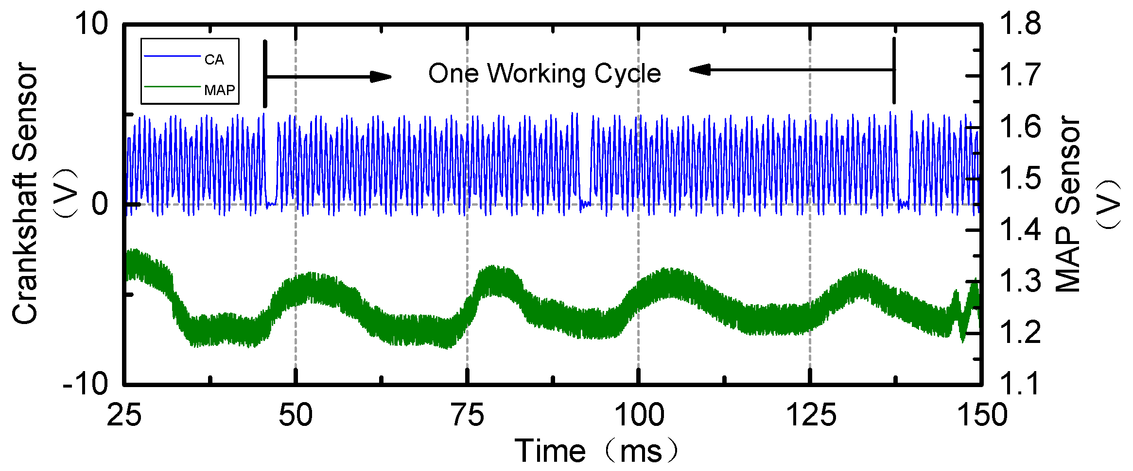
However, the cylinder air mass, which is controlled by the inlet and outlet valves, is difficult to directly obtain and have event-based dynamics that are based on the crank angle domain. There are two main implementation challenges. One is because the engine working conditions are really complicated and defined by both the engine speed and load. During the transient operation, the air mass through the throttle may be different from the cylinder air mass. At the steady operating conditions, the intake air mass can be dynamically balanced. The other is because the intake pressure that is measured by the sensor is fluctuated, even at the steady state because of the valve movement. As the pressure signal recorded by the oscilloscope, as shown in Figure 2, using the sensor installed in the intake manifold with a fluctuated signal during each cycle is a challenge for predicting the actual cylinder air mass. The transient air mass flow through the intake valve is difficult to measure directly by sensors, and the cylinder air must be estimated while using the control observer. In this work, the intake air observer is developed based on commonly used MAP sensor on the car, and one MAF sensor is additionally installed to calibrate the parameters at steady state.
Moreover, the accurate parameters of the intake air path are usually difficult to determine with certainty. The modeling of the intake path of the SI engine and the parameter fitting are the significant basis for the observer design.

2.2. Mathematical Description of the Intake Air Path

From the SI engine, it is difficult to derive the precise model for the control purpose. The engine system is a highly nonlinear and multi-variable system. The mean value engine model (MVEM) is suitable for real-time simulation and it has acceptable accuracy for representing engine dynamics for the control application [12,13]. Additionally, MVEM has been shown to be quite accurate for the intake air mass observer design [2]. It describes the physical engine dynamics on the time scale of several engine events without the cycle-to-cycle characteristics. In this section, the intake air mathematical description of the SI engine is specifically analyzed based on MVEM.
The intake air dynamics expresses the filling behavior in the manifold with the air mass via the throttle plate ( m ˙ a t ) inlet, while at the same time drawing air mass into the cylinder ( m ˙ a p ). The manifold pressure state equation is acquired based on the ideal gas law [14,15]:
p ˙ m a n = R T m a n V m a n ( m ˙ a t m ˙ a p )
where R is the gas constant of fresh air 287 J/(kg∙K) and V m a n is the volume of the intake manifold (L). T m a n is the manifold air temperature (K) and p m a n is the manifold air pressure (kPa). The throttle air mass flow can be physically modeled as two separated parallel isentropic flows [16]:
{ m ˙ a t = m ˙ a t 1 p a m b T a m b β 1 ( α ) β 2 ( p r ) p r = p m a n p i n β 1 ( α ) = 1 a 1 cos ( α ) + a 2 cos 2 ( α ) β 2 ( p r ) = { 1 p n ( p r p 1 p r p 2 ) ,   if   ( p r p c ) 1 ,   if   ( p r < p c ) p c = ( p 1 p 2 ) ( 1 p 2 p 1 ) p n = p c p 1 p c p 2
where p r is the ratio of air pressure before and after the throttle plate, m ˙ a t 1 is a fitting constant, α is the throttle opening angle(degree), β 1 ( α ) ,   β 2 ( p r ) are the empirical equations, p a m b and T a m b are the ambient air pressure and temperature, and a1, a2, p1, p2, pn, pc are constant parameters that have been found in [16].
It is difficult to use the ideal gas law to calculate the real intake air mass in the cylinder because the cylinder pressure and temperature cannot be measured in practice. Accordingly, volumetric efficiency ( e v ) is introduced to observe the amount of air in each cylinder by the pressure and temperature measured in the manifold. Using the speed density formula:
m ˙ a p = V d 120 R T m a n ( e v p m a n ) n = V d 120 R T m a n ( s i p m a n y i ) n
where Vd is the engine displacement (L), n is the engine velocity (RPM), and si, yi are speed dependent fitting parameters and they should not change much over the engine operating range.
Above all, the mathematical description of the intake air path could be modeled by Equations (1)–(3). It is obvious that the model structure matches the experience that the intake air is different at each working condition determined by the throttle opening angle (α) and engine speed (n).

2.3. SI Engine AFR Control Problem Formulation

The AFR control purpose is to regulate the air-fuel mixture ratio at a proper value under different working conditions. It should be noted that the fuel mass flow rate in the cylinder ( m ˙ f c y l ) needs to adapt the cylinder intake air mass flow rate ( m ˙ a p ) based on the definition of AFR, the parameters are determined by:
{ AFR = m ˙ a p m ˙ f c y l λ = AFR AFR s = 1 ϕ
The AFR controlling strategy is complicated and the design objective is to track a desired air-fuel ratio ( ϕ r e f ) at different working conditions that have the ability of rejecting disturbances. ϕ r e f is the stoichiometric value for calibration requirements in practice. It is a challenging work to handle the control problems of parameter uncertainties and variations, the time-delay and nonlinearities, the large modeling uncertainties and unknown dynamics, and the wide operating range and complex working conditions. The adaptive AFR controller was introduced to overcome the control problems that are mentioned above [17]. From the definition in Equation (4), the in-cylinder air mass estimation is a crucial part for the fuel injection calculation and it affects the AFR control results. As a consequence, the accurate intake air mass observation is a key solution in order to regulate the AFR at expected value using the advanced control method.

3. Observer-Based Intake Air Mass Estimation

3.1. Discrete Sampling Based on Engine Operation Cycle

Although the dynamic engine operation process is a continuous-time system, the digital controller should obtain the system at the discrete-time domain for the control applications. The movement of the inlet and outlet valves are based on the camshaft in each engine working cycle that corresponded to four-stroke events. Consequently, the sampling time is not constant and is varied by the engine speed. On the other hand, the timing is constant in rotation domain that also can be treated as crank-angle based sampling. For the four-cylinder engine discussed in this paper, the engine speed can be:
n = 1 6 d θ d t
where θ is the crank angle (°) and n is the engine velocity (RPM). In addition, to transform the time-domain differential equation into the crank-angle domain, note that:
d x d t = 6 n d x d θ
Therefore, the event-based sampling can be implemented each 720° crank angle each engine cycle and the sampling time can be T = 120 / n .

3.2. Model Parameter Fitting

Based on Equations (1) and (3), the air pressure in the intake manifold can be:
p ˙ m a n = R T m a n V m a n ( m ˙ a t m ˙ a p ) = R T m a n V m a n m ˙ a t V d n 120 V m a n ( s i p m a n y i )
assuming k t = R T m a n V m a n and k n = V d n 120 V m a n , we have the intake air mass equation:
{ p ˙ m a n = k t m ˙ a t k n ( s i p m a n y i ) = k t m ˙ a t k n s i p m a n + k n y i = k n s i p m a n + u u = k t m ˙ a t + k n y i
where u is assumed as the system input. Accordingly, the discrete air mass model can be:
p m a n ( k + 1 ) = ( 1 T k n s i ) p m a n ( k ) + T u ( k )
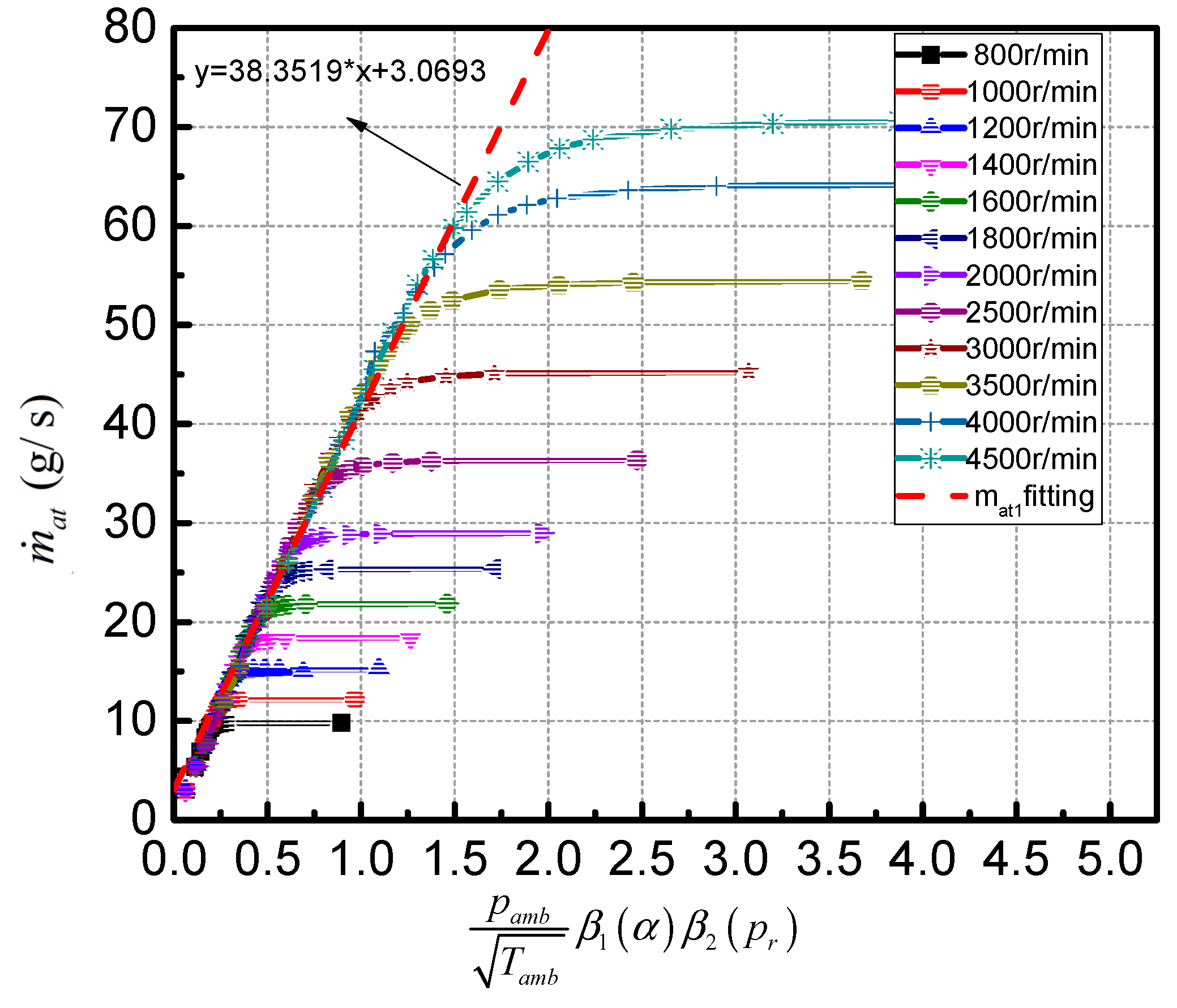
As the air pressure in the manifold changes much faster than the engine speed, kn, kt, u can be treated as constant at each sampling point. Based on Equation (2), while using the MAF and MAP sensor, the m ˙ a t can be fitted using the experiment data at the different engine speed as the result in Figure 3.
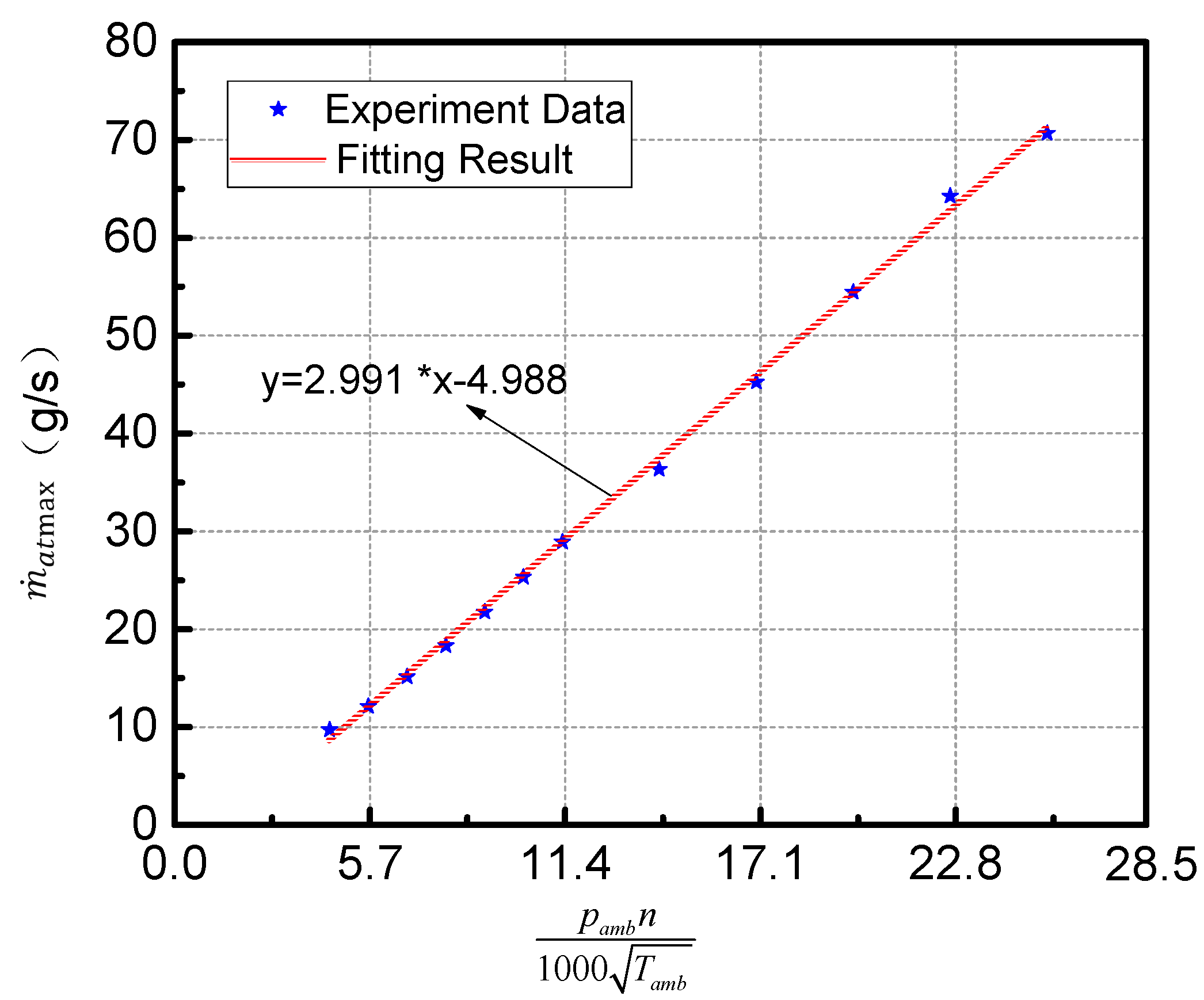
It is obvious that the m ˙ a t was linear at each engine speed condition when ( p a m b / T a m b ) β 1 ( α ) β 2 ( p r ) was at a small value, and then m ˙ a t reached to a maximum value. In order to find out the maximum throttle air mass m ˙ a t max at each engine speed, we obtained the fitting experimental result, as shown in Figure 4.
As the result, the air mass passes the throttle m ˙ a t ( α , p m a n , n ) at different operation points can be estimated, as below:
{ m ˙ a t = 38.3519 p a m b T a m b β 1 ( α ) β 2 ( p r ) + 3.0693 m ˙ a t max = 2.991 p a m b N 1000 T a m b 4.988 m ˙ a t ( α , p m a n , n )   =   m i n ( m ˙ a t , m ˙ a t max )
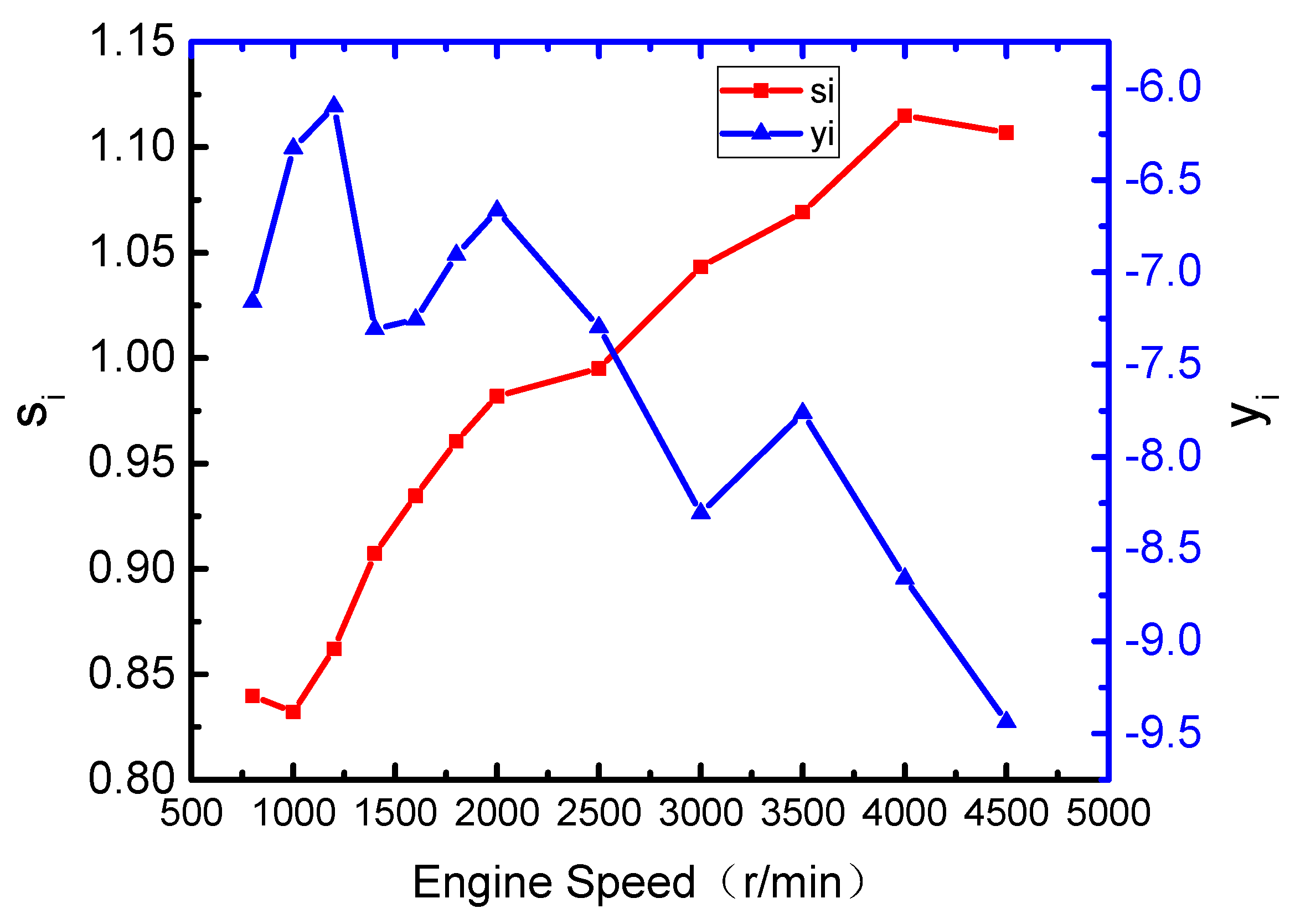
In addition, MAF measurement can be used to represent the in-cylinder air mass at the steady state. Based on the Equation (3), the experimental data that are shown in Figure 5 indicate that s i p man y i is linear at the different engine load if the engine speed remains steady, and so that the si and yi can be treated as constant. The fitted si and yi alone with the engine speed is shown in Figure 6.
For the intake air mass mathematical model in Equation (8), all of the parameters are obtained using the data fitting method, as mentioned above.

3.3. Intake Air Mass Observer

We use a time-varying extended Kalman predictor [18] for the optimal estimation of the intake manifold air pressure, which can minimize the effort of pump gas fluctuation, random noise, and measurement noise. We consider the system description in Equation (6), the state space model is then given as follows at the sampling time T = 120/n:
{ p ^ m a n ( k + 1 ) = F a p ^ m a n ( k ) + G a u ( k ) + K a [ p m a n ( k ) p ^ m a n ( k ) ] z ( k ) = p ^ m a n ( k )
where F a = 1 T k n s i is the state-transition vector, G a = T is the control-input vector, and K a is the Kalman gain matrix. The predicted covariance estimate is P ( k + 1 / k ) = F a ( k ) P ( k / k ) F a T ( k ) + Q ( k ) , the near-optimal Kalman gain is K a ( k + 1 ) = P ( k + 1 / k ) [ P ( k + 1 / k ) + R ( k ) ] 1 , and then update the state estimate by p ^ m a n ( k + 1 ) = p ^ m a n ( k + 1 / k ) + K a ( k + 1 ) [ p m a n ( k + 1 ) p ^ m a n ( k + 1 / k ) ] . Q k and R k are the covariance matrices of the zero mean multivariate Gaussian state and observation noises, respectively. The in-cylinder air mass prediction can be obtained based on Equation (3):
m ^ a p = t i o t i c m ˙ a p d t = 30 n V d 120 R T m a n ( s i p ^ m a n y i ) n = V d 4 R T m a n ( s i p ^ m a n y i )
where t i c and t i o are the intake valve opening and closing time, which has a different value along with the engine speed at 180° crank angle. As mentioned above, the solving process of the intake air observer is as the calculating steps that are shown in Figure 7 based on Equations (8)–(12).

4. Experimental Verification

4.1. Experimental Test Bench

The experimental validation was conducted on a SGMW B15 engine test bench to verify the effectiveness of the illustrated intake air mass observer and the prediction results of cylinder intake flow. The engine geometry dimensions are listed in Table 1. Figure 8 shows the control system scheme of the engine test bench. A BOSCH HFM5 MAF sensor was installed in front of the throttle plate. The other necessary sensors and actuators were using the original OEM parts for the engine control application. The engine ECU was implemented on a Freescale MC9S12XDP512 based controller. An ATI Vision based calibration system was established to acquire the control parameter online updating and internal data logging [17].

4.2. The Experimental Results

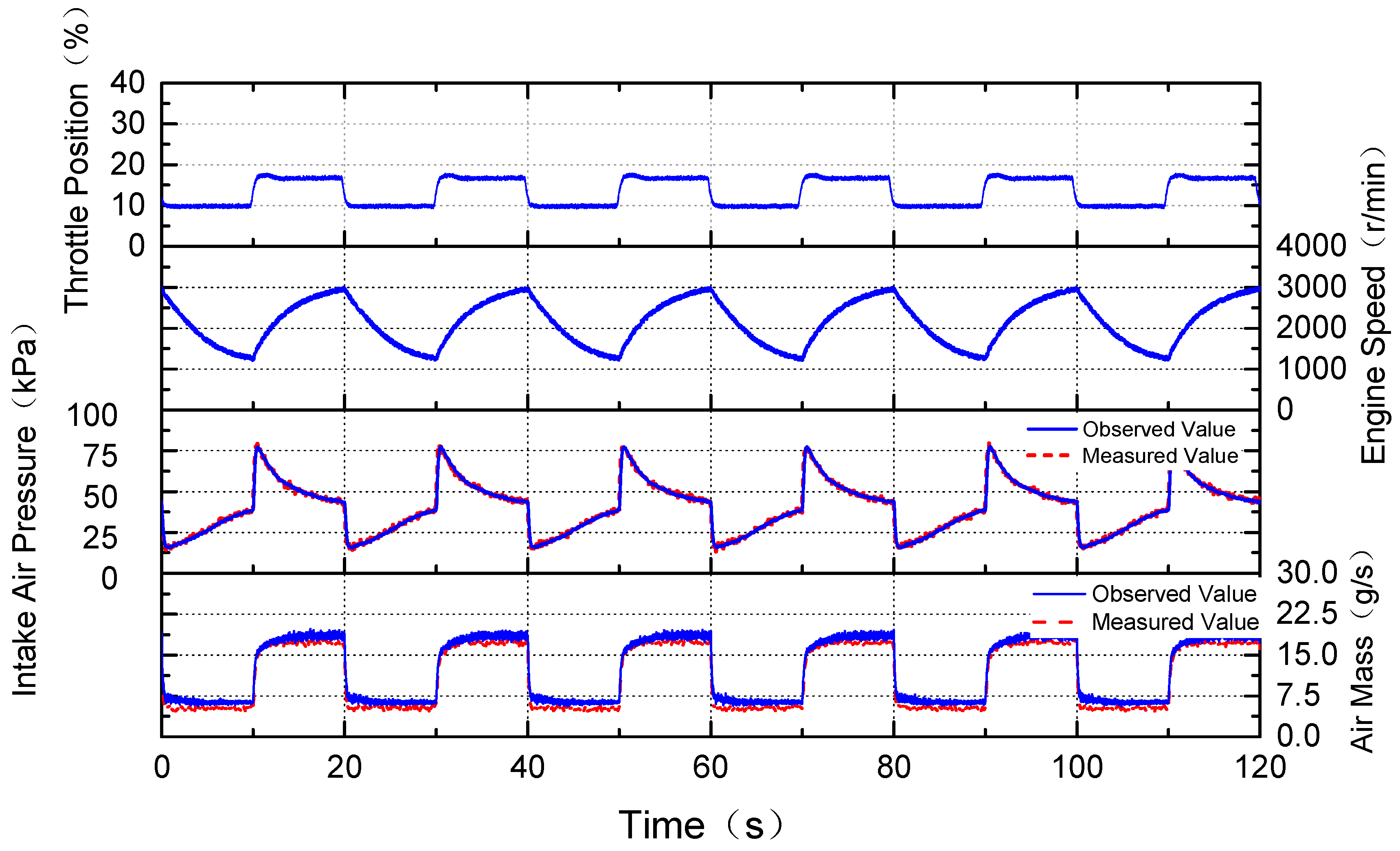
The ECU controller was set as open-loop control strategy mode for the observer test verification, and the CCP calibration software is used to collect real-time parameters inside the controller. The dynamometer was set at a constant load of 40 N∙m and the engine speed fluctuated between about 1200 r/min. and 3000 r/min. by applying an 8–16% square wave disturbance to the throttle valve. The intake air pressure was averaged to four times an engine cycle to reduce the effect of pump loss. Figure 9 shows the experimental results.
It can be seen that the observed value of intake air pressure using the Kalman filter had a better noise suppression than the measured value. The air flow at the engine intake valve could not be directly measured by sensors. Accordingly, in the experiment, the cylinder air that was predicted by the observer was compared with the intake air flow measurements by the installed HFM5 sensor. In Figure 9, it was obvious that the intake air pressure increased when the engine speed decreased and the pressure decreased when the engine speed increased at the constant throttle position. This followed the physical properties of the SI engine. It also showed that the air mass estimated by the observer responded faster when compared with the measured value by MAF sensor when the throttle position changed at transient. There was a certain difference between the measured and observed air mass, the main reason might be the response speed of the sensor, the installation position and the measurement characteristic that determined the measured value was not equal to the transient intake air mass flow through the inlet valve. Furthermore, there was some inevitably certain error that existed in the parameter fitting process of the observer design to cause the error. However, in general, the prediction results from the observer can effectively describe the intake dynamics and achieve satisfactory prediction accuracy, which can be used to observe the cylinder intake air mass in the air-fuel ratio control application. The air-fuel ratio error that was caused by the observer could be compensated by the feedback control method.
For the AFR control application, a comparable experimental result is shown in Figure 10. The ECU controller was designed differently about the control algorithm by using the measured intake air pressure based on Equation (3) and using the intake air mass observer. The engine speed was fixed at 1500 RPM and the throttle position fluctuated near 6% to conduct the intake air mass varying. The exhaust AFR was measured by the UEGO sensor and then recorded by the calibration system. It was obvious that the exhaust AFR has a better noise suppression while using the observer method and the transient overshoot was less. However, the fluctuation of the AFR was remarkable, because the open-loop controller could not overcome the AFR variation based on the engine dynamics. Using the extended Kalman predictor for intake air mass observation has a reasonable optimization for the AFR control application.

5. Conclusions

An intake air mass observer design that was based on extended Kalman filter for the port-injected SI engine is presented in this work. To estimate the cylinder air mass for the AFR control application, the air path dynamics modeling and air mass observer design were implemented based on MVEM. The parameters of the model were carried out by the experimental data fitting method. A detailed analysis of the observer design was introduced while using the extended Kalman filter method. The comparative experiments were conducted on an engine test bench to validate the performance of the proposed intake air mass observer.
The experiment results could show that the proposed intake air mass observer is effective for the cylinder air mass estimation, which is unable to be directly measured by sensors. Although the computation process became more complicated, using the intake air mass observer based on the extended Kalman filter could obtain the acceptable estimated cylinder air mass for the AFR control application and also have a better response time when compared with the MAF sensor. Future work will involve the intake air observer with the optimal AFR control for SI engine at different operating conditions.

Author Contributions

All authors have cooperated for the preparation of the work. conceptualization, L.M. and X.Y.; methodology, L.M. and C.Z.; software and validation, L.M. and J.L.; writing—Original draft preparation, L.M. and X.Y.; writing—Review and Editing, J.L. and X.Y.

Funding

This research was funded by National Natural Science Foundation of China, grant number 61903287 and Fundamental Research Funds for the Central Universities, grant number WUT: 2018IVA109. This work also supported by Nature Science Foundation of Hubei Province, grant number 2018CFB303.

Conflicts of Interest

The authors declare no conflict of interest.

References

  1. Jiao, X.; Zhang, J.; Shen, T.; Kako, J. Adaptive air-fuel ratio control scheme and its experimental validations for port-injected spark ignition engines. Int. J. Adapt. Control Signal Process. 2015, 29, 41–63. [Google Scholar] [CrossRef]
  2. Wang, Z.; Zhu, Q.; Prucka, R. A Review of Spark-Ignition Engine Air Charge Estimation Methods; SAE Technical Paper 2016-01-0620; SAE international: Warrendale, PA, USA, 2016. [Google Scholar]
  3. Carbot-Rojas, D.A.; Escobar-Jiménez, R.F.; Gómez-Aguilar, J.F.; Téllez-Anguiano, A.C. A survey on modeling, biofuels, control and supervision systems applied in internal combustion engines. Renew. Sustain. Energy Rev. 2017, 73, 1070–1085. [Google Scholar] [CrossRef]
  4. Hendricks, E.; Vesterholm, T.; Sorenson, S.C. Nonlinear, Closed Loop, SI Engine Control Observers; SAE Technical Paper 920237; SAE international: Warrendale, PA, USA, 1992. [Google Scholar]
  5. Kang, J.M.; Haskara, I.; Wang, Y.Y.; Chang, C.F. Adaptive intake oxygen estimation in lean-burn engines. In Proceedings of the 2012 American Control Conference (ACC), Montreal, QC, Canada, 27–29 June 2012. [Google Scholar]
  6. Polóni, T.; Rohaľ-Ilkiv, B.; Arne Johansen, T. Mass flow estimation with model bias correction for a turbocharged Diesel engine. Control Eng. Pract. 2014, 23, 22–31. [Google Scholar] [CrossRef]
  7. Colin, G.; Bloch, G.; Chamaillard, Y.; Anstett, F. Two air path observers for turbocharged SI engines with VCT. Control Eng. Pract. 2009, 17, 571–578. [Google Scholar] [CrossRef] [Green Version]
  8. Stotsky, A.; Kolmanovsky, I. Application of input estimation techniques to charge estimation and control in automotive engines. Control Eng. Pract. 2002, 10, 1371–1383. [Google Scholar] [CrossRef]
  9. Efimov, D.; Li, S.; Hu, Y.; Muldoon, S. Application of interval observers to estimation and control of air-fuel ratio in a direct injection engine. In Proceedings of the 2015 American Control Conference (ACC), Chicago, IL, USA, 1–3 July 2015. [Google Scholar]
  10. Höckerdal, E.; Frisk, E.; Eriksson, L. EKF-based adaptation of look-up tables with an air mass-flow sensor application. Control Eng. Pract. 2011, 19, 442–453. [Google Scholar] [CrossRef]
  11. Ogawa, M.; Ogai, H.; Inoue, Y.; Okuda, N.; Ohata, A. Design of compensator for engine intake system model with turbocharger by Extended Kalman Filter. In Proceedings of the ICCAS-SICE 2009, Fukuoka, Japan, 18–21 August 2009. [Google Scholar]
  12. Hendricks, E. Engine Modelling for Control Applications: A Critical Survey. In Meccanica; Springer: Berlin/Heidelberg, Germany, 1997; Volume 32, pp. 387–396. [Google Scholar]
  13. Guzzella, L.; Onder, C.H. Introduction to Modeling and Control of Internal Combustion Engine Systems; Springer: Berlin/Heidelberg, Germany, 2010; Volume 25, pp. 96–99. [Google Scholar]
  14. Hendricks, E.; Vesterholm, T. The Analysis of Mean Value SI Engine Models; SAE Technical Paper 920682; SAE International: Warrendale, PA, USA, 1992. [Google Scholar]
  15. Lei, M.; Zeng, C.; Hong, L.; Jie, L.; Wen, L.; Li, X. Research on Modeling and Simulation of SI Engine for AFR Control Application. Open Autom. Control Syst. J. 2014, 6, 803–812. [Google Scholar] [CrossRef]
  16. Hendricks, E.; Chevalier, A.; Jensen, M.; Sorenson, S.C.; Trumpy, D.; Asik, J. Modelling of the Intake Manifold Filling Dynamics; SAE Technical Paper 960037; SAE international: Warrendale, PA, USA, 1996. [Google Scholar]
  17. Meng, L.; Wang, X.; Zeng, C.; Luo, J. Adaptive Air-Fuel Ratio Regulation for Port-Injected Spark-Ignited Engines Based on a Generalized Predictive Control Method. Energies 2019, 12, 173. [Google Scholar] [CrossRef]
  18. Chui, C.K.; Chen, G. Extended Kalman Filter and System Identification. In Kalman Filtering; Springer: Berlin/Heidelberg, Germany, 2017; pp. 115–137. [Google Scholar]
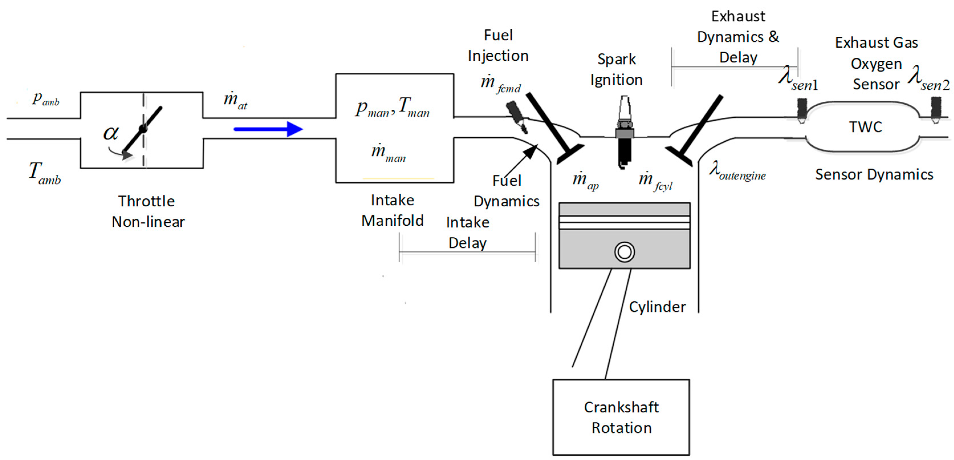
Figure 1. Structure of the SI engine air path.
Energies 12 03444 g001
Figure 2. The recorded air pressure signal.
Energies 12 03444 g002
Figure 3. The experimental fitting result of throttle air mass parameter m ˙ a t .
Energies 12 03444 g003
Figure 4. m ˙ a t max fitting results relative to engine speed and ambient temperature.
Energies 12 03444 g004
Figure 5. The fitting result of s i p man   -   y i alone with the intake pressure.
Energies 12 03444 g005
Figure 6. The calculated si and yi alone with the engine speed.
Energies 12 03444 g006
Figure 7. The calculating steps of the intake air observer.
Energies 12 03444 g007
Figure 8. The control system scheme of the engine test bench.
Energies 12 03444 g008
Figure 9. Experimental results of the intake air mass observation.
Energies 12 03444 g009
Figure 10. Experimental results of different intake air mass estimation.
Energies 12 03444 g010
Table 1. SGMW B15 Engine Specifications.
Parameter TypeValue
Engine TypeSI, 4 cylinders, In-line
Displacement (liters)1.485L
Compression Ratio10.2:1
Bore (mm)74.7
Stroke (mm)84.7
Maximum torque146 N∙m/3600–4000 RPM
Maximum power82 kW/5800 RPM