Abstract
Multi-phase motors have attracted increasing attention in fields seeking high reliability, such as electric vehicles, ships, and rail transit, as they exhibit advantages, such as high reliability and fault tolerance. In this study, we consider a 12-phase permanent magnet synchronous motor (PMSM). First, a mathematical model of the 12-phase PMSM in the static coordinate system is established and the model is simplified according to the constraint condition of neutral point isolation. Second, according to the principle of invariant magnetomotive force under normal and fault conditions, two optimal control strategies of winding current, i.e. maximum torque output (MTO) and minimum copper consumption (MCC), are proposed. For a single-phase open-circuit fault, two optimization methods are used to reconstruct the residual phase current, such that the motor can maintain normal torque output and exhibit lower torque ripple under the fault state. Finally, system simulation and experimental research are conducted; the results verify the accuracy and feasibility of the fault-tolerant control strategy of the 12-phase PMSM proposed in this paper.
1. Introduction
With the development and universal application of microcomputers, fault-tolerant technology has developed rapidly in multiprocessor systems, flying hoc networks, cloud computing, wireless sensor networks and so on [1,2,3,4]. In recent years, fault-tolerant technology has also received extensive attention in the field of multi-phase motor control. Owing to its remarkable high power density, high efficiency, and strong fault-tolerant ability, the multi-phase permanent magnet synchronous motor (PMSM) has attracted wide attention in high reliability fields, such as electric vehicles, ships, and rail transit [5,6,7,8,9]. The PMSM has a primary requirement of equipment safety and reliability, so faults must be detected and solved in time, and the system should be able to run with fault tolerance [10,11]. Compared with the traditional three-phase motor, the increase in the phase number of the multi-phase motor improves the redundancy of the system [12,13,14]. The core of the fault-tolerant control is an inverter with fault-tolerant capability [15]. At present, most research focuses on the hardware, reduced-order decoupling, and optimal current fault-tolerant strategies.
For hardware fault tolerance, a redundant bridge arm is added based on the original inverter. When a fault occurs, the fault phase is switched to the redundant bridge arm. However, this method increases costs and occupies space [16,17,18,19]. Compared with the hardware fault-tolerant strategy, the reduced-order decoupling and optimal current fault-tolerant strategies can achieve disturbance-free operation without increasing the requirement of hardware resources. For reduced-order decoupling fault-tolerant control, the control structure is reconstructed through the reduced-order decoupling matrix, which usually requires an additional compensation strategy [20,21].
For optimal current fault-tolerant control, it is necessary to control the alternating fault-tolerant current reference without changing the decoupling matrix of the motor. A. Tani, et al. in [22] deduced the expression of winding phase current for the fault-tolerant control with minimum copper consumption (MCC) based on the principle of invariant magnetomotive force (MMF) before and after faults; however, this method requires that the motors have odd winding phase numbers, and its application is limited. D. Ting, et al., J. Moon, et al., and A. K. M. Arafat, et al. in [23,24,25] have focused on the one-phase fault of the multi-phase motor, and compensated torque by changing the phase angle of the one-phase current; however, this method causes a large torque ripple. G. Feng, et al. in [26] have taken double three-phase permanent magnet synchronous motor as the research object, and the minimum torque ripple and maximum torque output as the target. A genetic algorithm is adopted to optimize the reference value of the remaining phase current under a one phase open-circuit fault. However, they did not consider the real-time performance of a fault tolerance algorithm, and the uniform expression of other healthy phase currents in the case of any phase open-circuit fault are not given. Moreover, the disadvantage of this method is that it involves complex calculations and is difficult to realize. Predictive current control, a method based on the accurate motor model, is also widely used in multi-phase motor systems because of its fast response and the absence of static error and overshoot. Here, because the motor model, prediction model, and objective function change before and after the fault, it needs to be re-modeled, and the implementation is more complex [27,28,29,30].
In view of the shortcomings of the above methods, this study considers a neutral-isolated 12-phase PMSM as the research object and constructs a fault-tolerant strategy based on normal decoupling transformation. First, the mathematical model of the 12-phase PMSM is established. Second, for the phase open circuit, according to the principle of the invariant MMF, the residual current is reconstructed by the two current optimization methods of maximum torque output (MTO) and MCC, respectively, so that the motor maintains the normal torque output under the fault condition, and a lower torque ripple is obtained. Finally, the system simulation and experimental research are performed, and results verify the accuracy and feasibility of the proposed method.
2. Mathematical Model of 12-Phase Permanent Magnet Synchronous Motor (PMSM)
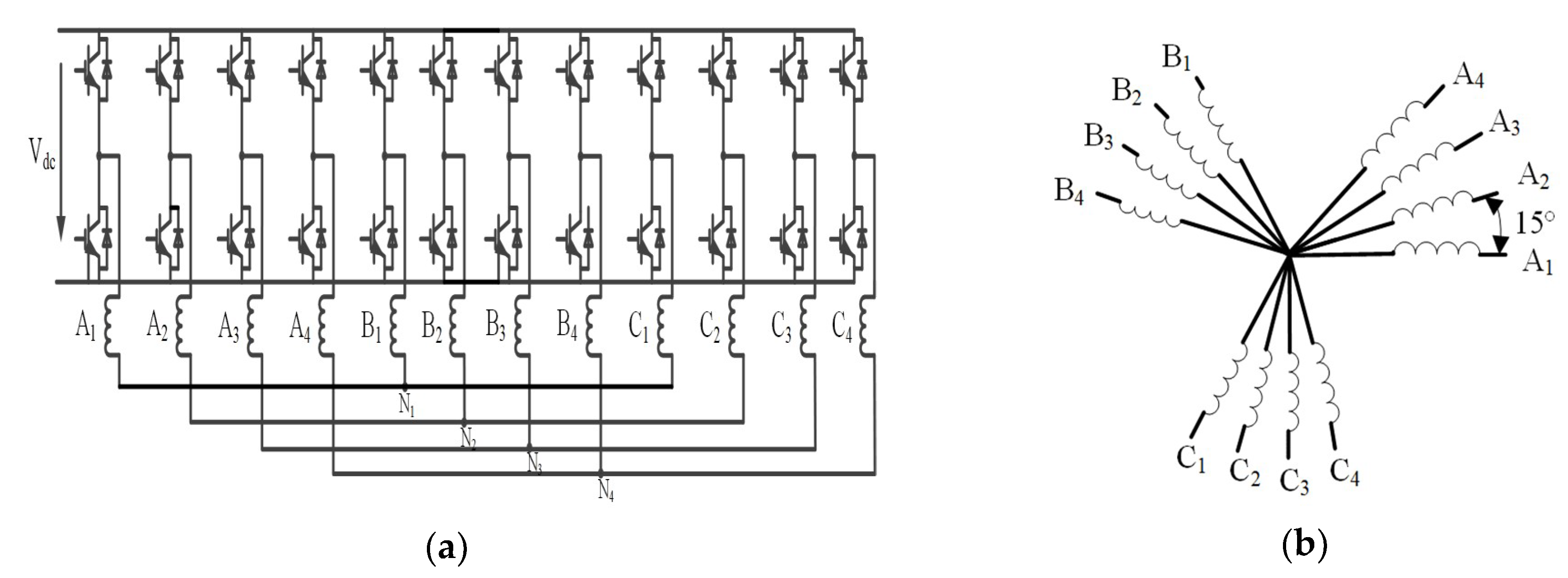
This study considers a 12-phase PMSM. Figure 1a shows the topology structure of a 12-phase motor system, and Figure 1b shows a schematic of the stator winding of the 12-phase PMSM, consisting of four sets of Y-connected three-phase windings with neutral-point isolation, which are spaced apart by 15°. According to the vector space decoupling theory, all the motor variables are mapped to six mutually orthogonal sub-planes of α-β, x1-y1, x2-y2, x3-y3, and o1-o2, o3-o4; the α-β sub-plane participates in electromechanical energy conversion, x1-y1, x2-y2, and x3-y3 are harmonic sub-planes, and o1-o2, and o3-o4 are zero-sequence planes. The coordinate transformation matrix is:
where, Ts is a twelve dimensional static transformation matrix; X represents motor variables such as voltage, current, flux linkage, etc.
where, xα, yβ are variables mapped to the fundamental sub-plane of α-β; xx1, xy1 are variables mapped to the harmonic sub-plane of x1-y1; xx2, xy2 are variables mapped to the harmonic sub-plane of x2-y2; xx3, xy3 are variables mapped to the harmonic sub-plane of x3-y3; xo1, xo2, xo3, xo4 are variables mapped to the zero sub-plane of o1-o2, o3-o4.
where, XA1, XB1, etc. are expressed respectively as currents of phase A1, phase B1, etc.

Figure 1.
Twelve-phase permanent magnet synchronous motor (PMSM) system: (a) topology structure of inverter; (b) winding distribution of neutral point isolation.
It is only necessary to perform a coordinate transformation on the α-β sub-plane participating in the electromechanical energy conversion through using the transformation matrix:
where, Tr is a rotation coordinate transformation matrix, as shown Figure 2, I10 is a unit matrix, θ is the rotor electrical angle.
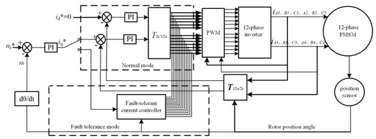
Figure 2.
Diagram of 12-phase PMSM with fault-tolerant ability.
The voltage equation is derived from the mathematical model of the motor:
where, Rs is the matrix of resistance coefficients.
The flux equation is derived from the mathematical model of the motor:
where, Ls is the matrix of inductance coefficients, ψm is the matrix of permanent magnet flux linkage.
The torque equation is expressed as:
where, θm is mechanical angle.
where, ψm1 is the scalar of fundamental magnitude of the flux linkage, γs1 is the matrix of flux linkage coefficients.
Where, Ls, Rs, Is, ψs, and γs1 are:
Here, ψm is the matrix of permanent magnet flux linkage, ψm1 is the scalar of fundamental magnitude of the flux linkage, γs1 is the matrix of flux linkage coefficients, θ is the rotor electrical angle, Is, and ψs are the winding phase current and linkage matrix, respectively, and np is number of the pole pairs.
3. Fault-Tolerant Control Strategy of 12-Phase PMSM
The fault-tolerant control strategy in this study adopts the same decoupling transformation in the normal and fault-tolerant operation modes of the system, simplifying the implementation of the fault-tolerant control strategy. The open-circuit fault discussed in this paper is an open circuit between the inverter and motor winding, and the motor winding is not damaged. Assuming that an open-circuit fault occurs in the A1 phase, if the decoupling transformation matrix remains unchanged, the voltage equation, flux equation, and torque equation will not be affected. According to the Equation (1), iβ, iy1, iy2, iy3, io2, io4 are independent of the A1 phase current, and iα, ix1, ix2, ix3, io1, io3 need to satisfy the following:
According to Equation (17), in the case of a one-phase open circuit, if the transformation matrix remains unchanged, the currents of the fundamental wave sub-plane and the harmonic sub-plane are no longer decoupled, so if the current of the harmonic sub-plane is continuously made zero, torque ripple will inevitably occur. The control freedom of the α-β sub-plane must be preferentially guaranteed, because the output torque of the motor is determined by theα-βsub-plane. The control freedom of the other sub-planes is related to the specific neutral connection mode. To ensure that the phase current has no direct current (DC) offset, the harmonic current reference can be written as follows:
Here, kn (n = 1,2, …, 12) is a coefficient determined by a specific mode and a fault-tolerant control method. Currently, the fault-tolerant control optimization method mainly includes two types: MCC and MTO.
3.1. Minimum Copper Consumption (MCC) Fault-Tolerant Mode of 12-Phase PMSM
The stator copper consumption of the 12-phase PMSM with four Y shifts of 15° can be expressed as:
The output torque is constant during the phase loss operation, i.e., the stator copper consumption corresponding to theα-βsub-plane is fixed, so the optimization condition of the stator MCC can be simplified as follows:
The neutral points of the four sets of windings are isolated, io1 = io2 = io3 = io4 = 0, and iy1, iy2, iy3 are not constrained by the A1 phase current, so the current reference of iy1, iy2, iy3 can be kept at zero when stator MCC is used, iy1 = iy2 = iy3 = 0; it can be written as follows:
By introducing Equation (18) into Equation (20), where Equation (20) is optimal target of the stator copper consumption, and Equation (21) is the constraint of Equation (20), the numerical solution of Equation (20) and Equation (21) is obtained by using the minimum value calculation function fmincon in the optimization toolbox of MATLAB, i.e.:
Applying Equation (22) to determine the current expressions of remaining phases, we obtain:
Here, Im is the current amplitude under normal operation, and, θ is the rotor electrical angle.
This method is suitable in other situations where other phases occur open-circuit. Table 1 lists the amplitude and initial phase of remaining currents when a winding current occurs open circuit. It can be seen from the table that the remaining two-phase current becomes 0.86 times of that under normal operation, and one of the remaining two-phase currents leads the other by 180° when there is a fault phase in a three-phase winding. Moreover, the amplitude of one phase current in each of the remaining three non-faulty windings is the same as that under normal operation.

Table 1.
Minimum copper consumption (MCC) fault-tolerant control strategies.
3.2. Maximum Torque Output (MTO) Fault-Tolerant Mode of 12-Phase PMSM
It can be seen from Equation (23) that the current amplitude of each phase is highly unbalanced in the stator MCC method, so stator MTO cannot be guaranteed in it. If MTO is taken as the optimization objective, the maximum phase current amplitude needs to be reduced as much as possible. Normal motor operation can be maintained as long as the MMFs generated by the residual phase current before and after the motor is out of phase are consistent with each other, because the electromagnetic torque is generated by the interaction between the MMF generated by stator winding current and the magnetic field of the permanent magnet.
According to the invariant principle of total MMF, the stator MMF of a 12-phase PMSM can be expressed as follows:
Here, N is the number of turns per phase winding. Taking the B1 phase as an example, the winding function is NB1 = 0.5Ncos(φ − 120°), φ is winding space angle, and the winding currents of the 12-phase motor in normal operation are:
Applying Equation (25) in Equation (24), the total MMF of the 12-phase PMSM in normal operation is written as follows:
Taking the open circuit of the A1 phase as an example, i.e., iA1 = 0, comparing Equations (24) and (26), to obtain the same resultant MMF, the remaining 10-phase current must satisfy:
The phase currents are expressed as the following:
According to Equation (28), the amplitude and phase of ix can be determined by optimizing the values of the parameters ax and bx. Applying Equation (28) in Equation (27), we obtain:
In addition to Equation (29), considering that the 12-phase motor adopts four sets of Y-type connections, the neutral points are isolated from each other, and thus the phase currents must satisfy the following constraints:
The maximum amplitude of phase current should be minimized as far as possible if the MTO is to be taken as the optimization objective, because the MTO cannot be guaranteed by the stator MCC method. Its objective function can be expressed as follows:
The ultimate optimization target is to find a set of solutions that satisfy the minimum residual phase current when the A1 phase is open-circuit. Equation (29) and Equation (30) is the constraint of Equation (31). It is difficult to solve them using the analytical method. The fminimax function in the MATLAB optimization toolbox can be used to obtain a solution that satisfies the condition, and the current expressions of the remaining phases are obtained as follows:
This method is suitable in other situations where other phases occur open-circuit. Table 2 shows the amplitude and initial phase of remaining currents when a winding current occurs open circuit. It can be seen from the table that the remaining two-phase current becomes 1.24 times of that under normal operation, and one of the remaining two-phase currents leads the other by 180° when there is a fault phase in a three-phase winding. Moreover, the amplitude of the two-phase currents in each of the non-faulty windings is the same as that of three-phase windings, which occur open-circuit.
Table 2.
Maximum torque output (MTO) fault-tolerant control strategies.
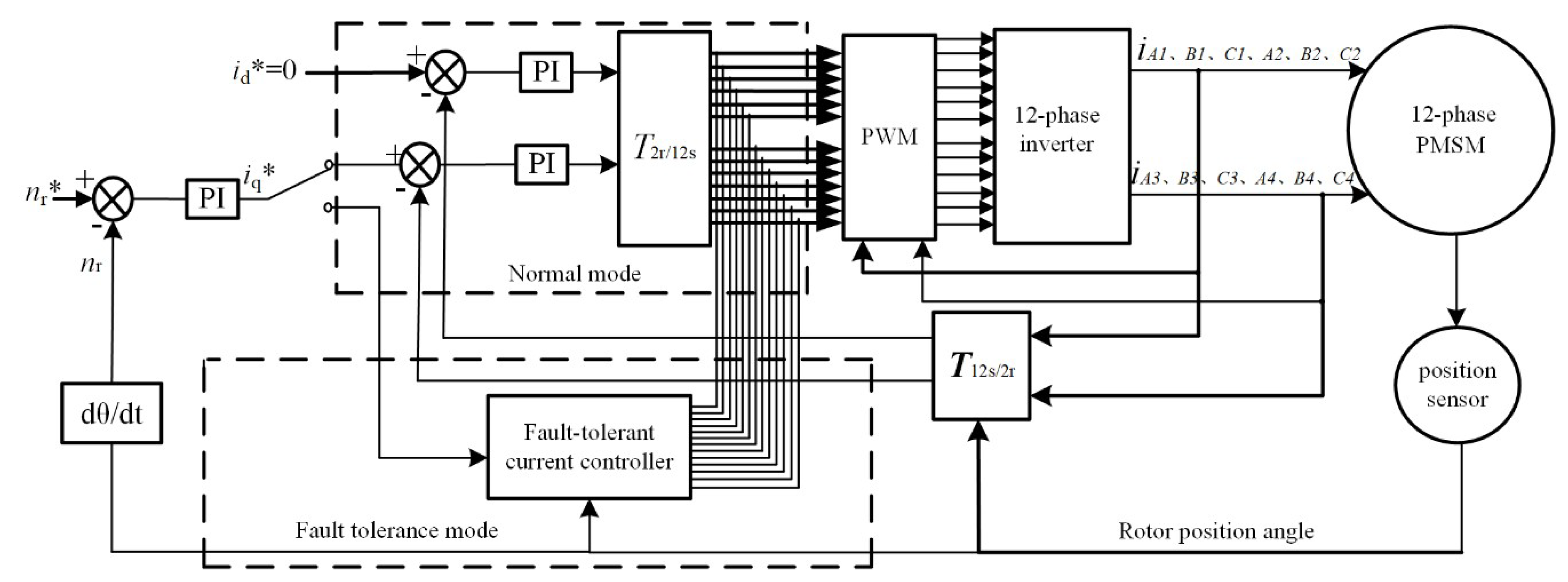
4. Simulation of 12-Phase Fault-Tolerant System
The fault-tolerant 12-phase PMSM control system is simulated through the MATLAB platform. The parameters are as follows: R = 1.4 Ω, Ld = 1.8 mH, Lq = 1.8 mH, ψf = 0.68 Wb, and the number of pole-pairs is 3, and the rated speed is 1000 r·min−1. The diagram of 12-phase PMSM with fault-tolerant ability is shown in Figure 2.
Figure 2, shows the diagram of switching between normal operation and fault-tolerant operation of 12-phase PMSM. This control system adopts vector control with id = 0, and its system is divided into internal and external loops, which are current loop and speed loop, respectively. Both controllers adopt the PI (Proportional Integral) regulator, and PI controller parameters are turned online in real time. T2r/12s is a block of d-q rotation transformation to 12-phase static coordinates, Ts is a block for transforming 12-phase stationary coordinates to 2-phase stationary coordinates, Tr is a block for 2-phase stationary coordinate transformation to d-q rotational coordinates, and the block of PWM generates the control signal of inverter to control the 12-phase motor.
4.1. Simulation of the Start-Up Process
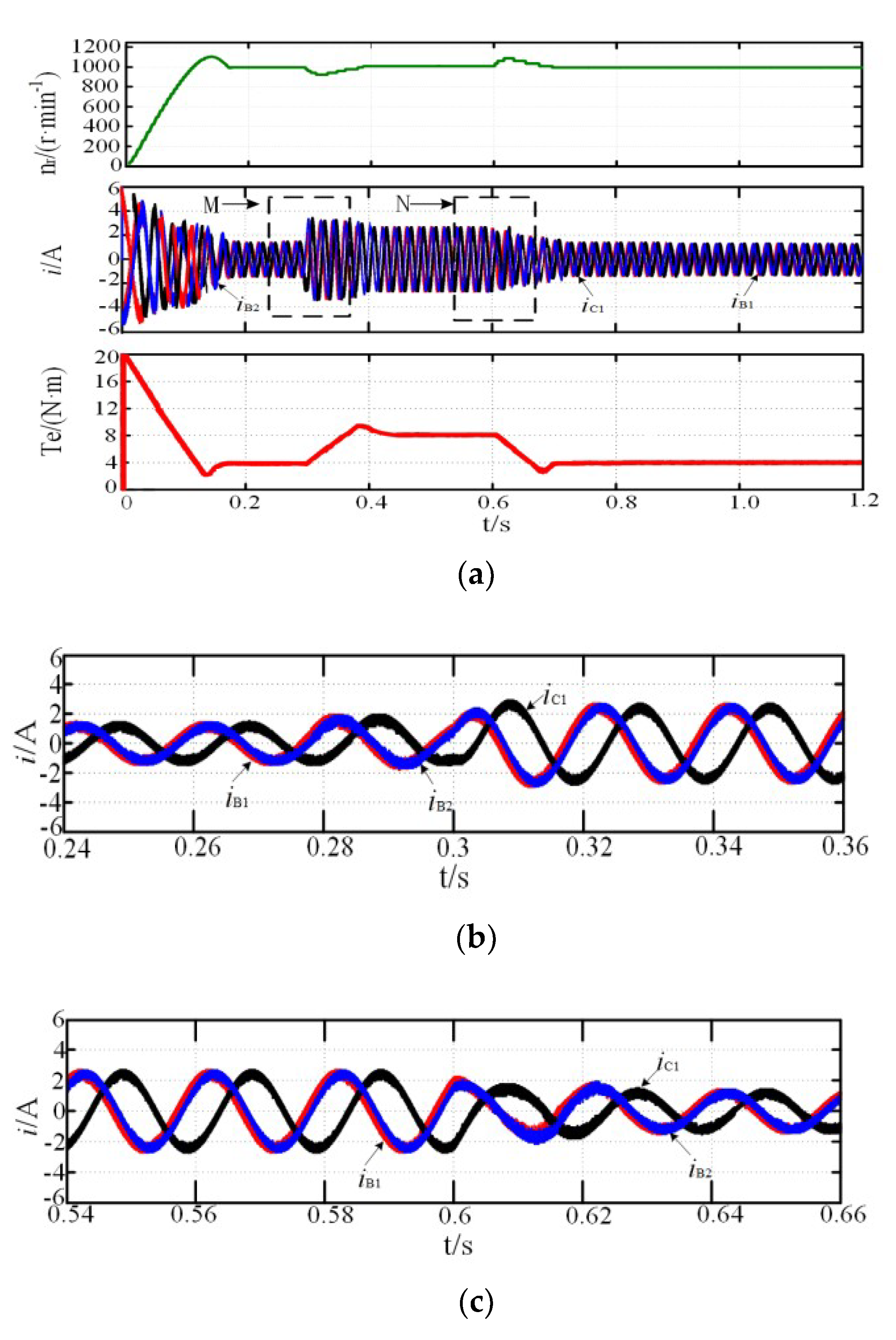
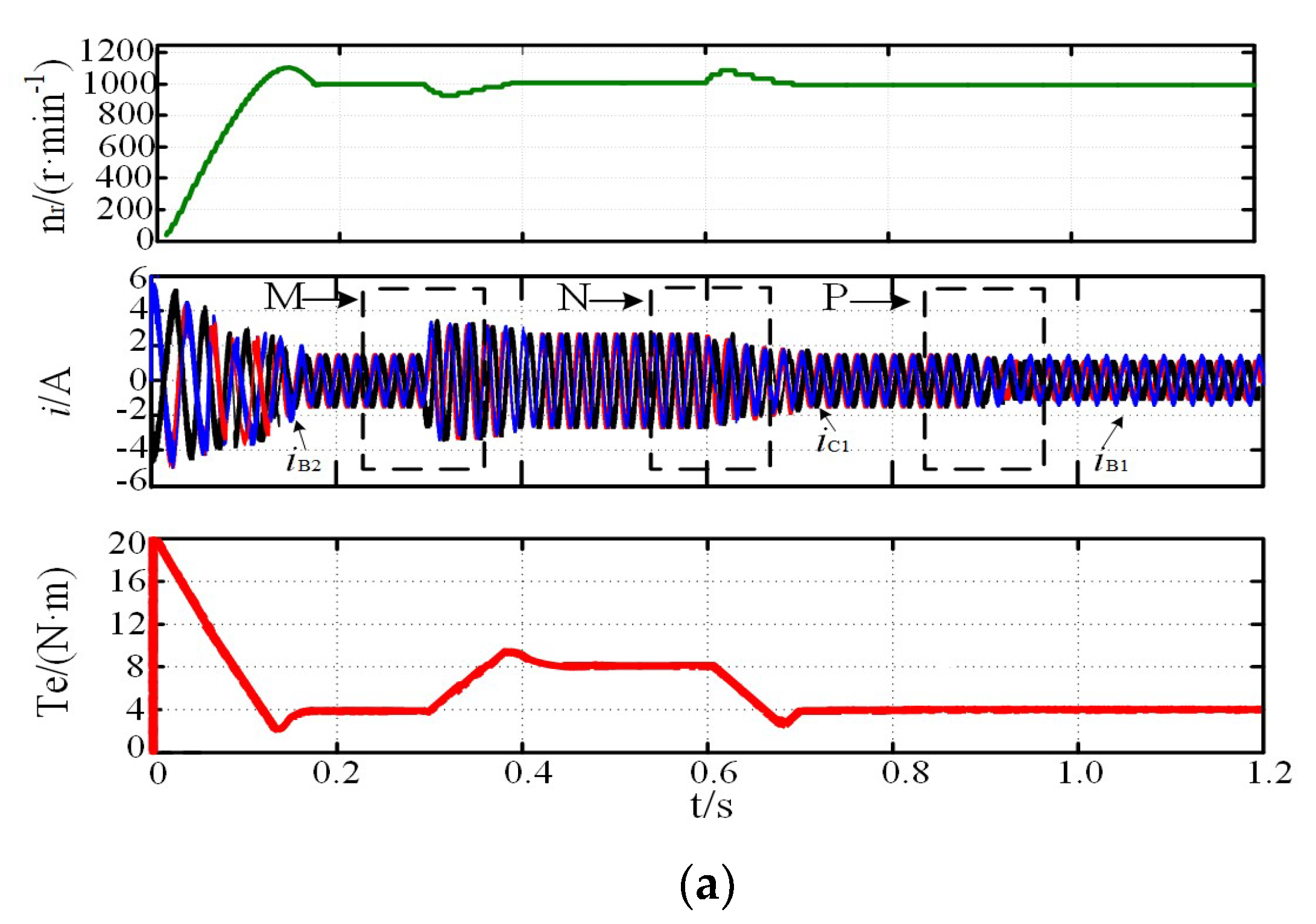
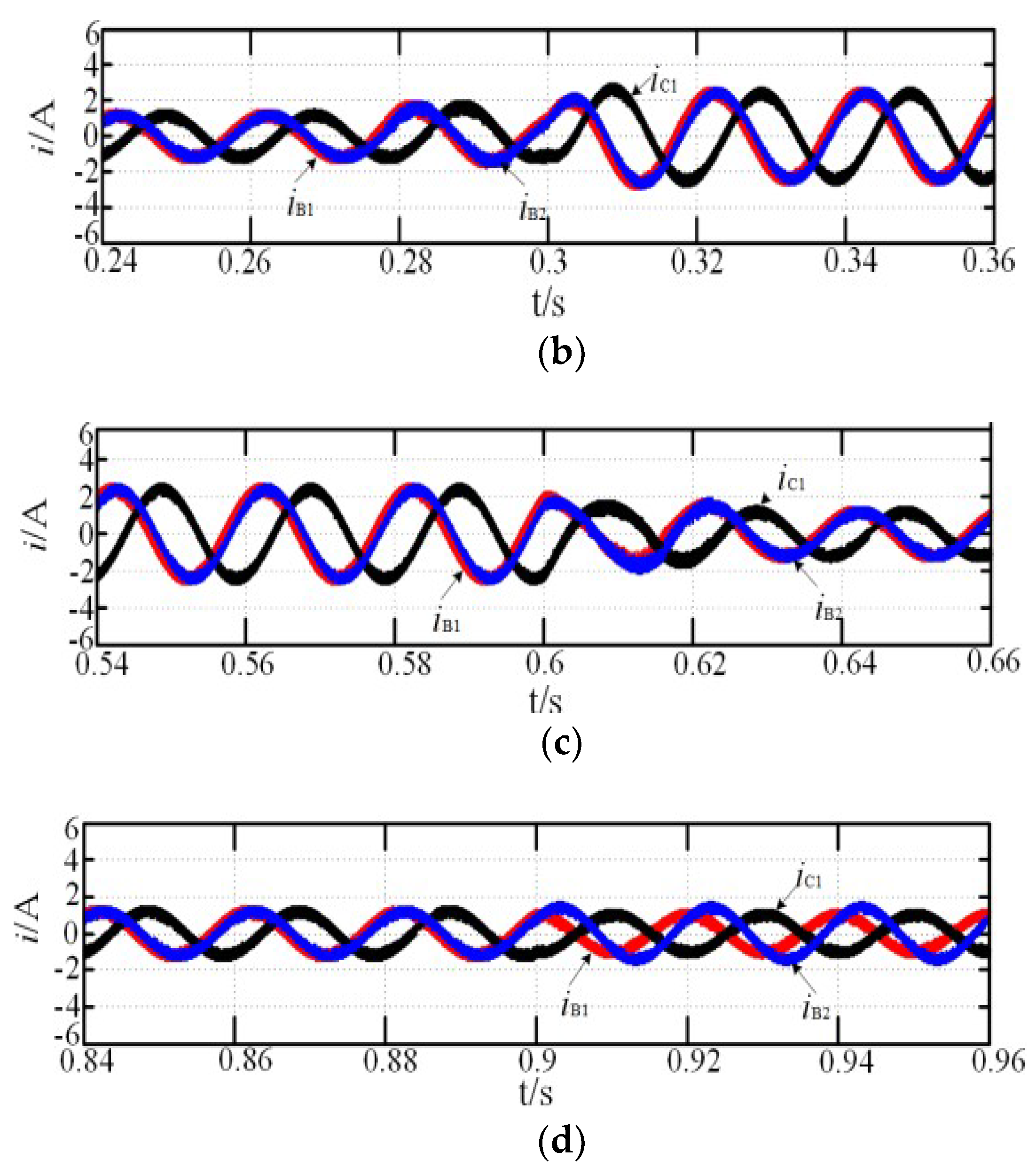
The motor reference speed, nr, was 1000 r·min−1, and the load torque, TN, was 4N·m, which suddenly increased to 8 N·m at 0.3 s and reduced to 4 N·m at 0.6 s. Figure 3, Figure 4 and Figure 5 show the system simulation during the normal and fault-tolerant start-up processes, respectively. iB1 leads iC1 by 120°, and iB1 leads iB2 by 15° during the normal operation, corresponding to the theoretical analysis above. While the motor speed can reach the reference rotor speed at 0.15 s, the rotor speed fluctuation was small when the load torque suddenly increased at 0.9 s, and the steady state was reached within 0.1 s, indicating that the system shows good dynamic and static performance. As shown in Figure 4a and Figure 5a, the two fault-tolerant modes are not significantly different from the normal operation mode, indicating that both fault-tolerant strategies show good start-up performance. In addition, the amplification of current in the case of increasing or decreasing load or fault-tolerance are respectively shown in Figure 3b,c, Figure 4b–d, and Figure 5b–d. The regions of M, N, and P in the figure are the magnification part of current, Te is electromagnetic torque.
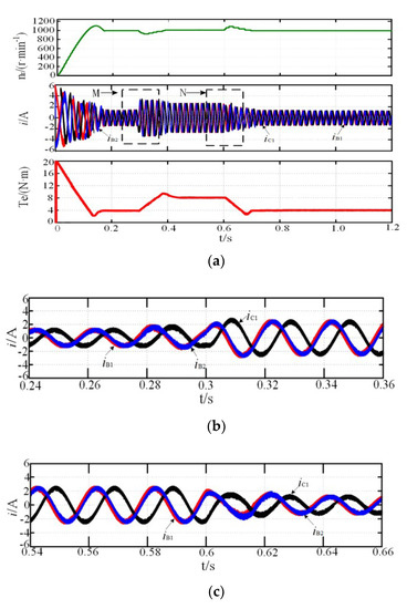
Figure 3.
Start-up process simulation: (a) normal; (b) magnification of M region; (c) magnification of N region.


Figure 4.
Start-up process simulation: (a) MCC; (b) magnification of M region; (c) magnification of N region; (d) magnification of P region.
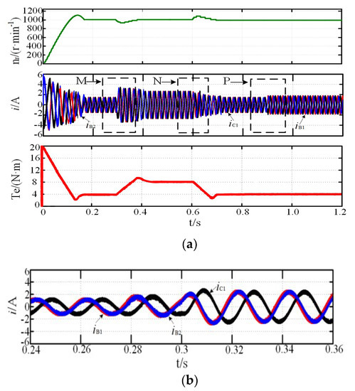
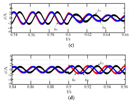
Figure 5.
Simulation of fault-tolerant operation: (a) MTO; (b) magnification of M region; (c) magnification of N region; (d) magnification of P region.
4.2. System Simulation of Fault-Tolerant Operation
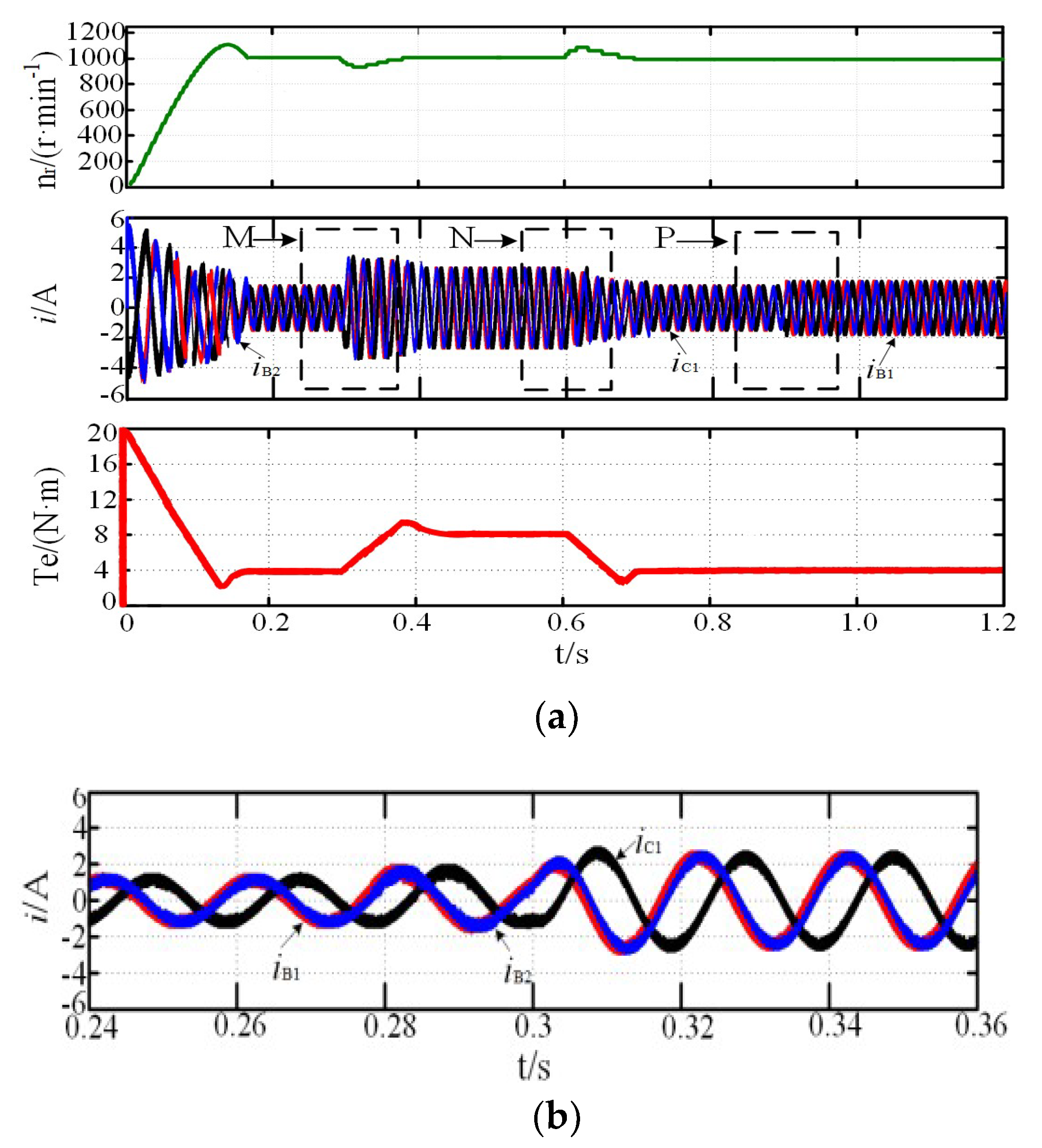
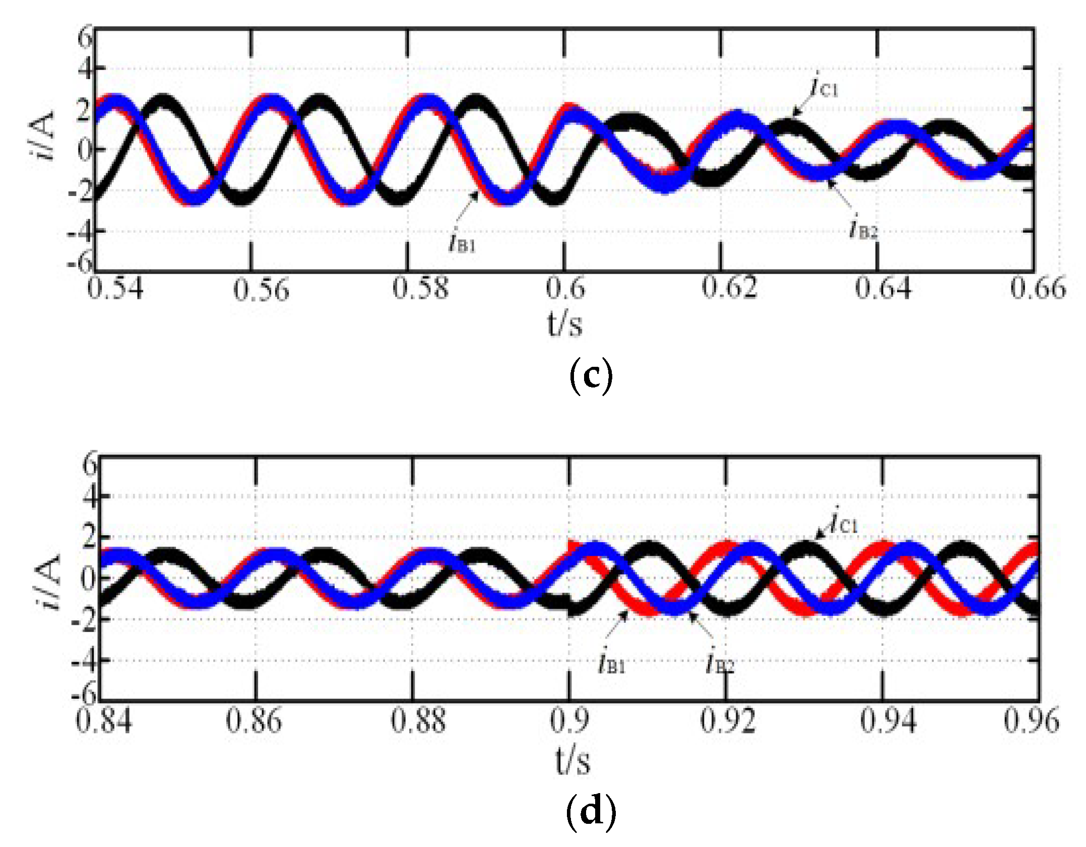
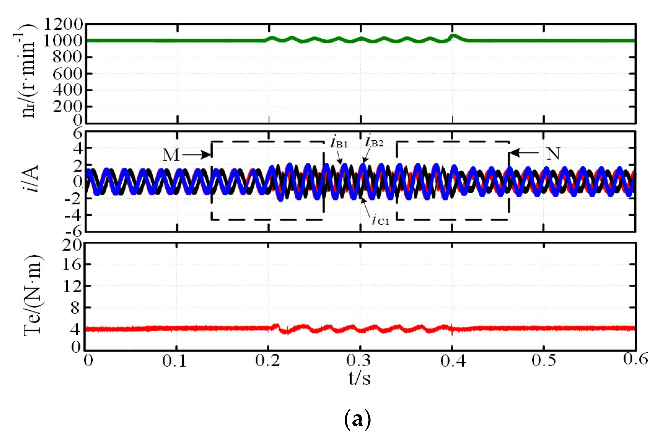
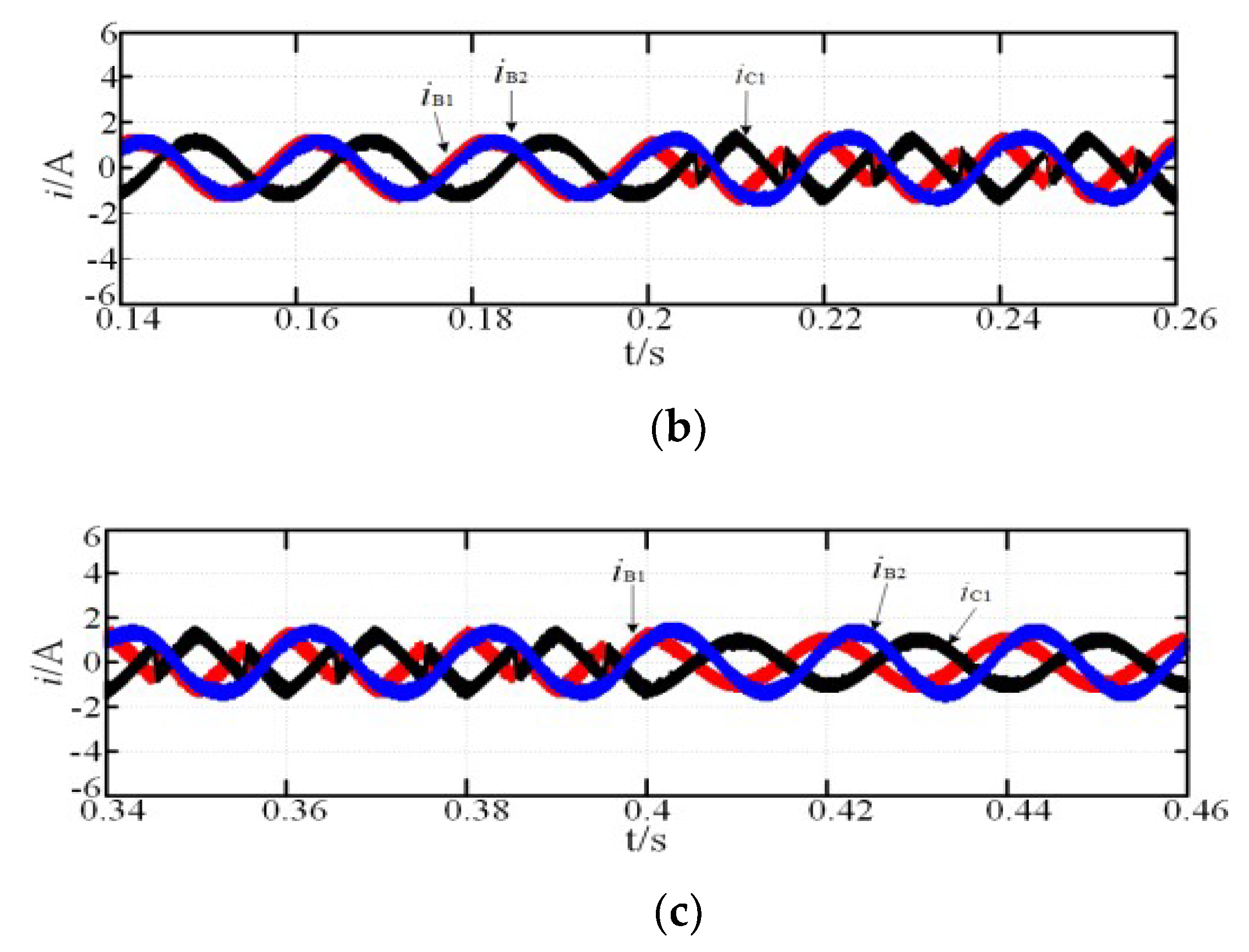
The reference speed was 1000 r·min−1, Te is electromagnetic torque, the load torque was 4 N·m, the open-circuit fault of the A1 phase occured at 0.2 s, and the fault-tolerant control strategy was adopted at 0.4 s. Figure 6a and Figure 7a, show the simulation results with the MCC and MTO strategies, respectively. There was no significant rotor speed fluctuation under the two types of fault-tolerant control strategies when the motor rotor speed reached the reference rotor speed, but there were changes in the amplitude and phase of the currents. When the MCC fault-tolerant control strategy was adopted, the phase currents were imbalanced, and the amplitude of the maximum phase current was increased to 1.31 times of that under normal operations. When the MTO fault-tolerant control strategy was adopted, compared with the phase current under the MCC control, the amplitude of each phase current decreased, and the maximum phase current amplitude was 1.24 times, and the minimum was 0.71 times of that under normal operation. It can be seen from Figure 6a and Figure 7a that the torque ripple was 21%, the rotor speed fluctuation was 3%, and at 0.4 s, the fault-tolerant control was adopted, and the current, speed, and torque were quickly restored to the steady state. The torque ripple was reduced from 21% to 4%, and the rotor speed fluctuation was reduced from 3% to 0.5%. Moreover, the M and N regions were magnified in Figure 6b,c and Figure 7b,c.
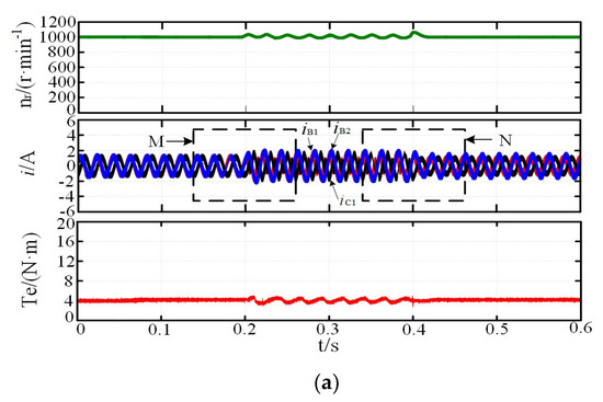
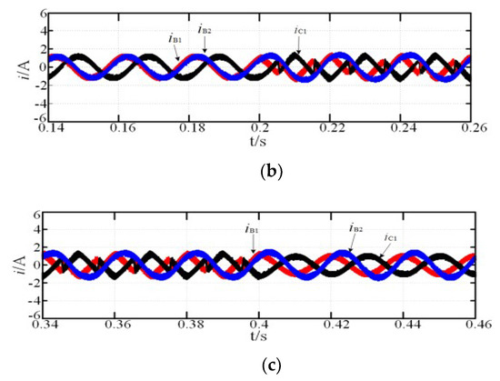
Figure 6.
Simulation of fault-tolerant operation: (a) MCC; (b) magnification of M region; (c) magnification of N region.
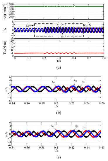
Figure 7.
Simulation of fault-tolerant operation: (a) MTO; (b) magnification of M region; (c) magnification of N region.
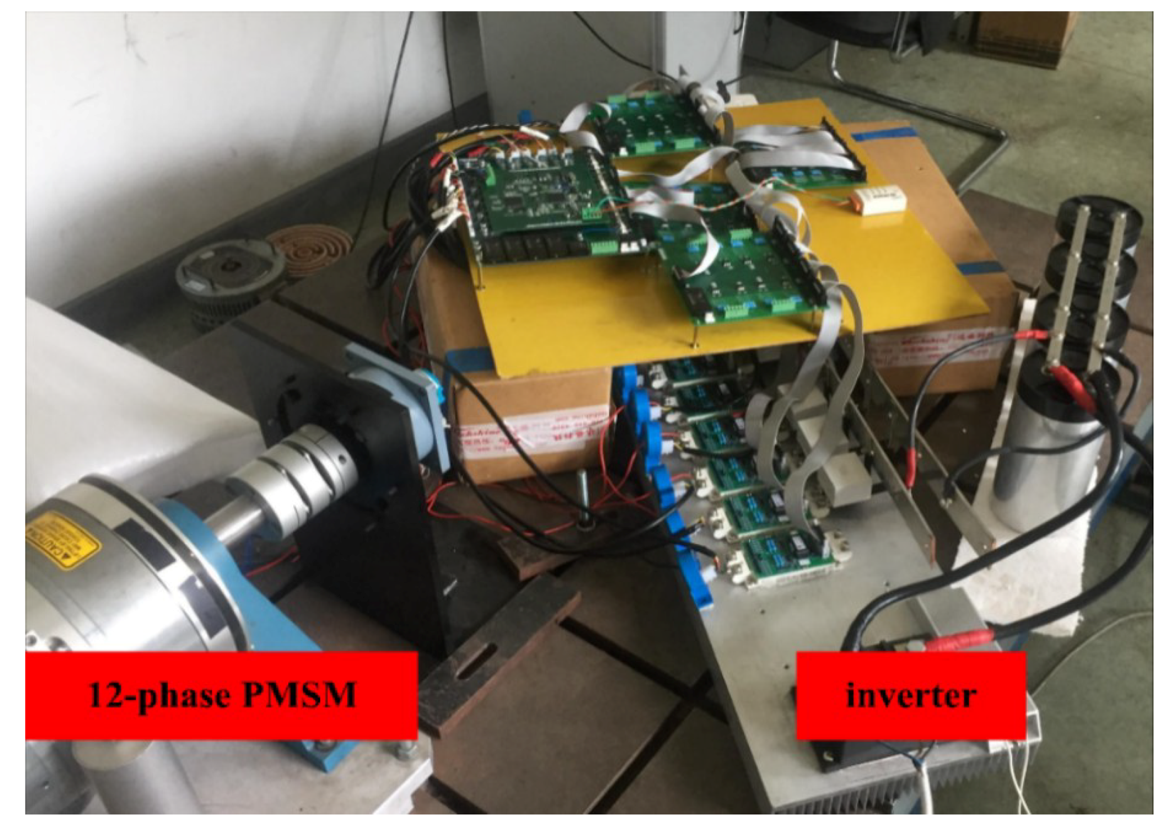
5. Experiment and Result Analysis
To verify the accuracy and effectiveness of the fault-tolerant control strategy proposed in this study, a 12-phase PMSM was selected for experimental verification, and parameters were kept consistent with simulation parameters. The experiment system platform is shown in Figure 8.
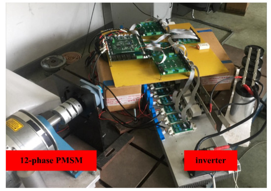
Figure 8.
Experiment’s system platform.
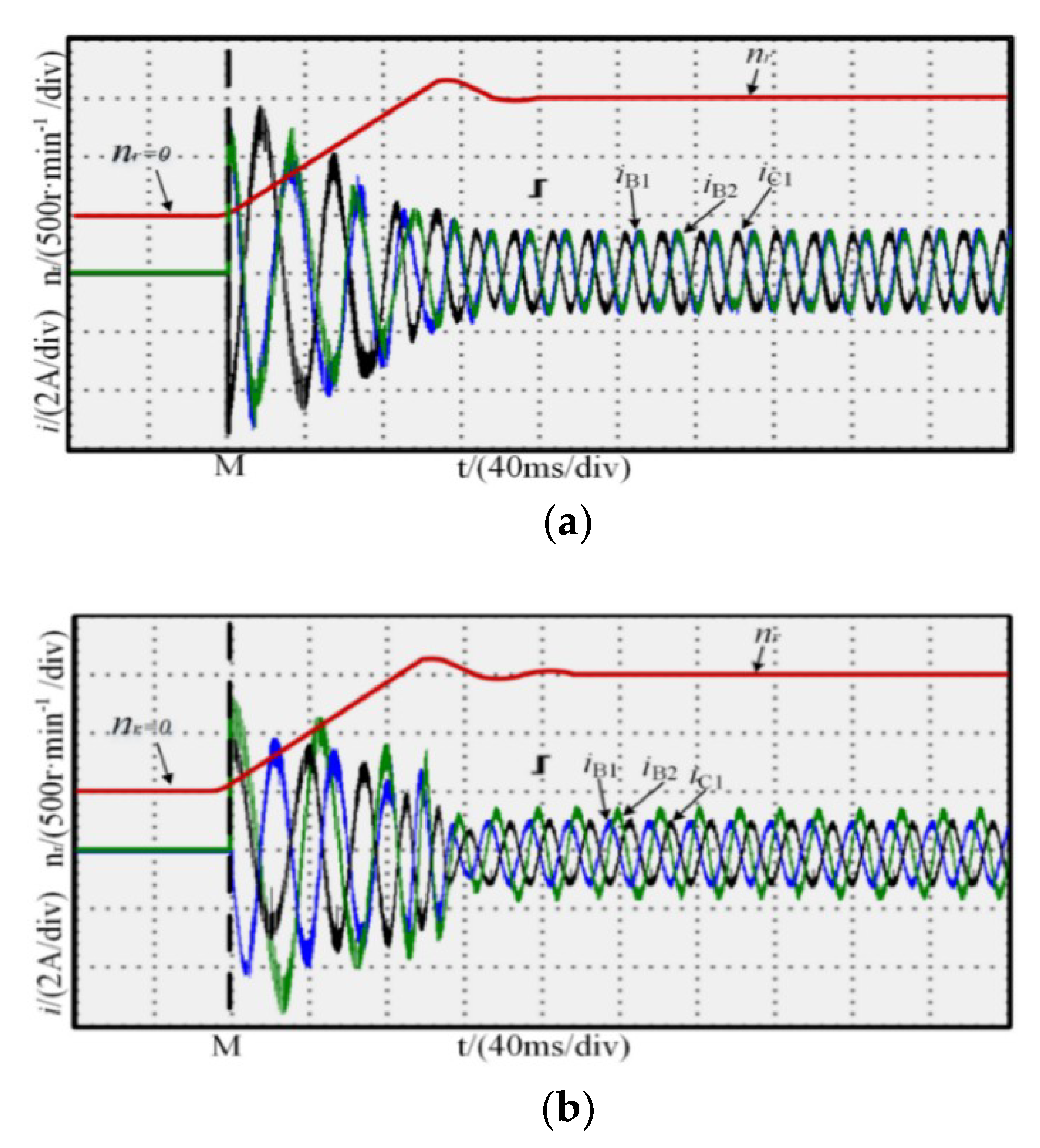
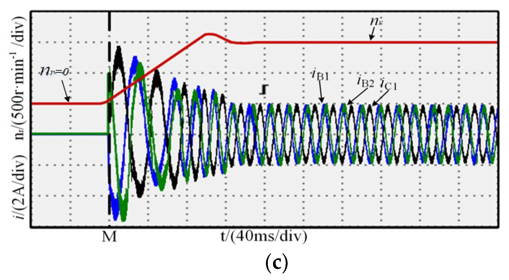
The rotor position is detected by a motor’s resolver, and when starting, speed adopts open-loop, and the output torque is so large that the motor can realize to speed up rapidly. For convenience, the time instant M was defined as the zero reference point, as shown in Figure 9. The figure shows the waveforms at the motor start for normal operation and one-phase open-circuit fault-tolerant operation; the rotor speed reached the reference speed within 0.15 s. There was no significant difference between the rotor speed in the normal and fault-tolerant operation modes, indicating that the fault-tolerant control strategy has good dynamic response capability.
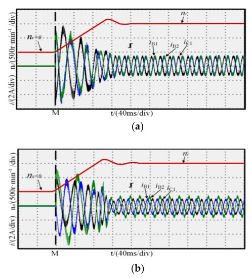

Figure 9.
Start-up process experiment: (a) normal; (b) MCC; (c) MTO.
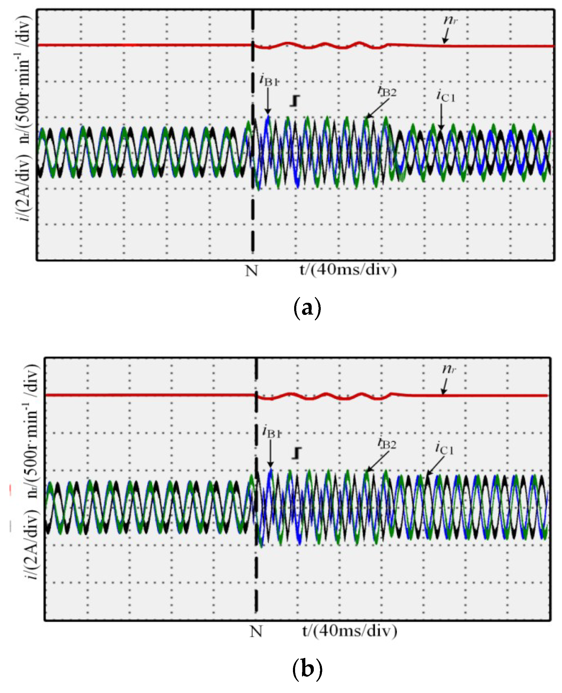
The motor reference rotor speed, nr, was 1000 r·min−1, the load torque, TN, was 4 N·m, the open-circuit fault of the A1 phase occured at 0.2 s of N, and after 0.12 s, the fault-tolerant control strategy was adopted. The experimental results of the online switching process from normal to fault to fault-tolerant operation are shown in Figure 10. When open-circuit fault occured in the A1 phase, the residual phase current was distorted, and the speed fluctuation was 3%. When the fault-tolerant control was adopted at 0.32 s, the speed fluctuation was reduced from 3% to 0.5%, the phase current and rotor speed quickly restored to the steady state, and the amplitude and phase of the current were consistent with the simulation results.
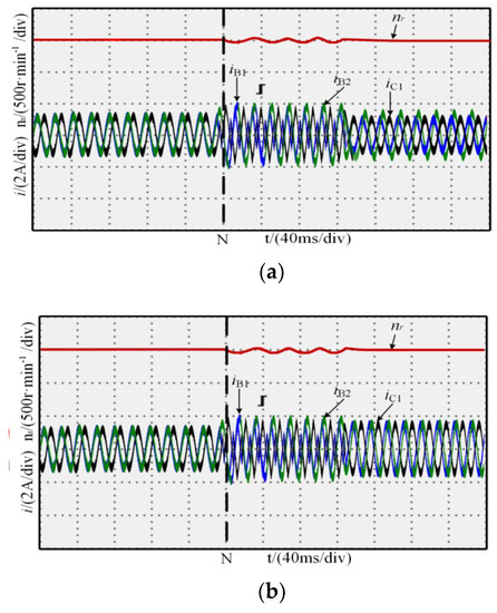
Figure 10.
Fault-tolerant control experiment: (a) MCC; (b) MTO.
6. Conclusions
In this study, the mathematical model of 12-phase permanent magnet synchronous motor is established in a static coordinate system, and the model is simplified according to the constraint condition of neutral-point isolation. At the same time, according to the principle of constant MMF under normal and fault conditions, a current control strategy with MCC and MTO as optimization targets is proposed. Both approaches have their own advantages, the motor winding loss is minimized when we adopted MCC under fault conditions. The amplitude of currents is too seriously unbalanced to guarantee the maximum torque output, however, the highest amplitude of the currents of MCC is smaller than that of MTO. Besides, the amplitude of the currents is almost the same, and the torque balance of each phase can be guaranteed when we adopted MTO under fault conditions. We adopt minimum and minimax function in the MATLAB to simplify constraint conditions, such as fault location, stator winding connection mode and control target, etc., and the global closed-loop solution of the residual phase current is carried out. In addition, the optimal residual reference current in the case of any phase open-circuit is given in this study, and the numerical solution of any phase current under fault conditions can be directly obtained by Table 1 and Table 2, which is simple and easy to operate, and ensure real-time performance and seamless switching between normal operation and fault-tolerant operation. Finally, the system simulation and experimental research are carried out. The results show that the control strategy proposed in this research can ensure the motor has good dynamic performance in normal operation and fault operation, and realize smooth switching between normal operation and fault operation. The above results verify the correctness and feasibility of the control method.
Author Contributions
H.G. conceived and designed the simulations and experiments; W.Z. analyzed the data; Y.W. and Z.C. wrote the paper and checked the paper.
Funding
This research work was funded by the National Natural Science Foundation of China grant number 51177031 and the Science and Technology Planning Project of Guangdong Province of China (2016B010135001).
Conflicts of Interest
The authors declare no conflict of interest.
References
- Guo, Q.; Yan, J.; Xu, W. Localized Fault Tolerant Algorithm Based on Node Movement Freedom Degree in Flying Ad Hoc Networks. Symmetry 2019, 11, 106. [Google Scholar] [CrossRef]
- Baek, H.; Lee, J. Task-Level Re-Execution Framework for Improving Fault Tolerance on Symmetry Multiprocessors. Symmetry 2019, 11, 651. [Google Scholar] [CrossRef]
- Wu, N.; Zuo, D.; Zhang, Z. Dynamic Fault-Tolerant Workflow Scheduling with Hybrid Spatial-Temporal Re-Execution in Clouds. Information 2019, 10, 169. [Google Scholar] [CrossRef]
- Peng, N.; Zhang, W.; Ling, H.; Zhang, Y.; Zheng, L. Fault-Tolerant Anomaly Detection Method in Wireless Sensor Networks. Information 2018, 9, 236. [Google Scholar] [CrossRef]
- Lin, B.; Zhang, P.; Ding, S.; Hang, J.; Hu, C.; Wang, Q. Investigation of the modulation method of a five-phase permanent magnet synchronous motor drive system. In Proceedings of the 2018 13th IEEE Conference on Industrial Electronics and Applications (ICIEA), Wuhan, China, 31 May–2 June 2018; pp. 2435–2438. [Google Scholar]
- Kumar, P.A.; Kumar, K.V. Modelling, fault-analysis and vector-control implementation of a multi-phase induction motor. In Proceedings of the 2016 International Conference on Signal Processing, Communication, Power and Embedded System (SCOPES), Paralakhemundi, India, 3–5 October 2016; pp. 870–876. [Google Scholar]
- Lin, X.; Huang, W.; Jiang, W.; Zhao, Y. Robust Direct Torque Control for Six-Phase Symmetrical Winding Permanent Magnet Synchronous Motor. In Proceedings of the 2018 IEEE Energy Conversion Congress and Exposition (ECCE), Portland, OR, USA, 23–27 September 2018; pp. 6537–6541. [Google Scholar]
- Wang, P.; Zheng, P.; Wu, F.; Zhang, J.; Li, T. Research on dual-plane vector control of five-phase fault-tolerant permanent magnet machine. In Proceedings of the 2014 IEEE Conference and Expo Transportation Electrification Asia-Pacific (ITEC Asia-Pacific), Beijing, China, 31 August–3 September 2014; pp. 1–5. [Google Scholar]
- Munim, W.N.W.A.; Che, H.S.; Hew, W.P. Fault tolerant capability of symmetrical multi-phase machines under one open-circuit fault. In Proceedings of the 4th IET Clean Energy and Technology Conference (CEAT 2016), Kuala Lumpur, Malaysia, 14–15 November 2016; pp. 1–6. [Google Scholar]
- Zhou, H.; Zhao, W.; Liu, G.; Cheng, R.; Xie, Y. Remedial Field-Oriented Control of Five-Phase Fault-Tolerant Permanent-Magnet Motor by Using Reduced-Order Transformation Matrices. IEEE Trans. Ind. Electron. 2017, 64, 169–178. [Google Scholar] [CrossRef]
- Chen, Y.; Song, J.; Zhang, J.; Huang, Q. Design and analysis of six-phase fault-tolerant PMSM for electric vehicle. In Proceedings of the 2016 Prognostics and System Health Management Conference (PHM-Chengdu), Chengdu, China, 19–21 October 2016; pp. 1–6. [Google Scholar]
- Wang, X.L.; Zhong, Q.C.; Deng, Z.Q.; Yue, S.Z. Fault-tolerant control of multi-phase permanent magnetic bearingless motors. In Proceedings of the XIX International Conference on Electrical Machines (ICEM 2010), Rome, Italy, 6–8 September 2010; pp. 1–6. [Google Scholar]
- Mohammadpour, A.; Parsa, L. A Unified Fault-Tolerant Current Control Approach for Five-Phase PM Motors with Trapezoidal Back EMF Under Different Stator Winding Connections. IEEE Trans. Power Electron. 2013, 28, 3517–3527. [Google Scholar] [CrossRef]
- Wang, W.; Zhang, J.; Cheng, M. Fault-Tolerant Control of Dual Three-Phase Permanent-Magnet Synchronous Machine Drives Under Open-Phase Faults. IEEE Trans. Ind. Electron. 2017, 32, 2052–2063. [Google Scholar] [CrossRef]
- Hosseyni, A.; Trabelsi, R.; Iqbal, A. Fault Tolerant Vector Controlled Five-phase Permanent Magnet Synchronous Motor Drive with an Open Phase. In Proceedings of the 2018 15th International Multi-Conference on Systems, Signals & Device (SSD), Hammamet, Tunisia, 19–22 March 2018; pp. 780–784. [Google Scholar]
- Zhu, J.; Niu, X.B. Investigation of short-circuit fault-tolerant brushless permanent magnet AC motor drive with redundancy. In Proceedings of the 2010 5th IEEE Conference on Industrial Electronics and Applications, Taichung, Taiwan, 15–17 June 2010; pp. 1238–1242. [Google Scholar]
- Freire, N.M.A.; Cardoso, A.J.M. A Fault-Tolerant PMSG Drive for Wind Turbine Applications with Minimal Increase of the Hardware Requirements. IEEE Trans. Ind. Appl. 2014, 50, 2039–2049. [Google Scholar] [CrossRef]
- Wang, G.; Wang, Z.; Wang, D.; Li, Y.; Li, M. A Review on Fault-Tolerant Control of PMSM. In Proceedings of the 2017 Chinese Automation Congress (CAC), Jinan, China, 20–22 October 2017; pp. 3854–3859. [Google Scholar]
- Wu, F.; Zheng, P.; Jahns, T.M. Six-Phase Fault-Tolerant Permanent Magnet Motors Drives with Reduced Switch Counts: Topology Comparisons and Hardware Demonstration. In Proceedings of the 2015 IEEE Transportation Electricfication Conference and Expo (ITEC), Dearborn, MI, USA, 14–17 June 2015; pp. 1–6. [Google Scholar]
- Changpan, Z.; Wei, T.; Xiangdong, S.; Zhaoji, Z.; Guijie, Y.; Jianyong, S. Control strategy for dual three-phase PMSM based on reduced order mathematical model under fault condition due to open phases. J. Eng. 2018, 2018, 489–494. [Google Scholar] [CrossRef]
- Huang, Q.-L.; Yong, C.; Li, X. Fault-Tolerant Control Strategy for Five-Phase PMSM with Third-Harmonic Current Injection. IEEE Access. 2018, 6, 58501–58509. [Google Scholar] [CrossRef]
- Tani, A.; Mengoni, M.; Zarri, L.; Serra, G.; Casadei, D. Control of multiphase induction motors with an odd number of phases under open circuit phase faults. IEEE Trans. Power Electron. 2012, 27, 565–577. [Google Scholar] [CrossRef]
- Ting, D.; Fenghui, L.; Li, S. Fault-tolerant method for six-phase PMSM by adjusting phase angle. In Proceedings of the 2017 20th International Conference on Electrical Machines and Systems (ICEMS), Sydney, Australia, 11–14 August 2017; pp. 1–5. [Google Scholar]
- Moon, J.; Lee, W.; Park, S.; Kim, J. Fault tolerant control method of seven-phase BLDC motor in asymmetric fault condition due to open phase. In Proceedings of the 2015 9th International Conference on Power Electronics and ECCE Asia (ICPE-ECCE Asia), Seoul, South Korea, 1–5 June 2015; pp. 1591–1596. [Google Scholar]
- Yarlagadda, A.K.; Eate, V.K.; Babu, Y.S.K.; Chakraborti, A. A Modified Seven Level Cascaded H Bridge Inverter. In Proceedings of the 2018 5th IEEE Uttar Pradesh Section International Conference on Electrical, Electronics and Computer Engineering (UPCON), Gorakhpur, India, 2–4 November 2018; pp. 1–6. [Google Scholar]
- Feng, G.; Lai, C.; Li, W.; Tjong, J.; Kar, N. Open-phase Fault Modeling and Optimized Fault Tolerant Control of Dual Three-phase Permanent Magnet Synchronous Machines. IEEE Trans. Power Electron. 2019, 34, 11116–11127. [Google Scholar] [CrossRef]
- Barrero, F.; Prieto, J.; Levi, E.; Gregor, R. An Enhanced Predictive Current Control Method for Asymmetrical Six-Phase Motor Drives. IEEE Trans. Ind. Electron. 2011, 58, 3242–3252. [Google Scholar] [CrossRef]
- Fei, M. Multi-phase synchronous motors: Minimum dissipation fault-tolerant controls. In Proceedings of the International Symposium on Power Electronics Power Electronics, Electrical Drives, Automation and Motion, Sorrento, Italy, 20–22 June 2012; pp. 219–224. [Google Scholar]
- Barrero, F.; Arahal, M.R.; Gregor, R.; Toral, S.; Duran, M.J. One–step Modulation Predictive Current Control Method for the Asymmetrical Dual–three phase Induction Machine. IEEE Trans. Ind. Electron. 2009, 56, 974–1983. [Google Scholar] [CrossRef]
- Guzmán, H.; Durán, M.J.; Barrero, F.; Toral, S. Fault-tolerant current predictive control of five-phase induction motor drives with an open phase. In Proceedings of the 2011 37th Annual Conference of the IEEE Industrial Electronics Society (IECON), Melbourne, Australia, 7–11 November 2011; pp. 3680–3685. [Google Scholar]

© 2019 by the authors. Licensee MDPI, Basel, Switzerland. This article is an open access article distributed under the terms and conditions of the Creative Commons Attribution (CC BY) license (http://creativecommons.org/licenses/by/4.0/).