Abstract
In this study, both zinc oxide (ZnO) nanorods and aluminum-doped zinc oxide (AZO) nanosheets were deposited by hydrothermal growth on fluorine-doped tin oxide (FTO) glass. After a photoanode was added to ZnO nanorods or AZO nanosheets, the photovoltaic conversion efficiency (PCE) increased due to improved electron transport and enhanced dye absorption. The improvement in electron transport was verified by electrochemical impedance spectroscopy (EIS), and the increase in dye absorption was verified by ultraviolet-visible spectroscopy. Both of these factors facilitated an increase in PCE. Parameters for dye-sensitized solar cells (DSSCs) using ZnO nanorods/TiO2 and AZO nanosheets/TiO2 photoanodes were tested and the results were recorded using EIS. The results indicated that the addition of the ZnO nanorods increased the short-circuit current density (Jsc) from 9.07 mA/cm2 to 10.91 mA/cm2, the open circuit voltage (Voc) from 0.68 V to 0.70 V, and the PCE from 3.70% to 4.73%, respectively. When the DSSCs were produced in a parallel silver-grid device, the results showed that PCE could be increased from 3.67% to 4.04% due to the reduction in connection resistance.
1. Introduction
Increased energy demands have accelerated fossil fuel depletion. Some researchers have predicted that certain remaining fossil fuel reserves will only last forty years, whilst others, like natural gas, will last around 60 years, and coal will last approximately 100 years [1]. For this reason, renewable fuels are growing in importance to both industry and researchers; for instance, wind power, hydropower, biomass energy, photovoltaics, and geothermal heat, are all undergoing intensive theoretical and practical development.
Among the currently available renewable energy technologies, photovoltaics are particularly promising. They provide the means to transfer sunlight into electrical energy [2,3,4,5,6]. Solar cell developments thus far have been divided into four generations: (1) silicon-based solar cells, (2) thin-film cells, (3) organic and nano-material cells, and (4) multi-layer composite cells. Silicon-based solar cells are confined to the terrestrial photovoltaic market, due to their high production cost. Compared to high-cost traditional silicon-based solar cells, dye-sensitized solar cells are a cost-effective photovoltaic device, with some notable advantages. The production process is simple, low-cost, and quick; furthermore, the end-product is more flexible in its range of possible applications, and it can also operate under low light intensities [7,8,9,10,11]. Due to the dye-sensitized solar cells’ (DSSCs) ability to work efficiently, even in very low light conditions such as at dawn or dusk, this makes them an extremely promising development in the field of photovoltaics.
DSSCs are composed of a photoanode, an electrolyte, and a counter electrode. In general, the material applied to the photoanode is titanium dioxide (TiO2), which also has a good compatibility with dye molecules. The material selected for the photoanode is extremely important as it is the principle component responsible for transforming the received sunlight into electrical power [12]; thus, the photovoltaic conversion efficiency of DSSCs can be improved by modification of the photoanode. The subject of this paper is enhancement of the photovoltaic conversion point, which, in this case, will be conducted by modification of the photoanode of the DSSC.
Ref. [13] introduced the use of zinc oxide (ZnO) nanowire (a kind of metal oxide semiconductor) into DSSCs, which is based on aluminum-doped zinc oxide (AZO) thin film. This was followed by studies using either graphene oxide (GO) and/or ZnO [14] as an active layer, to enhance the amount of dye-loading and decrease carrier transfer impedance. In addition, some researchers [15] used GO and magnetic beads (MBs) in the counter electrode for improved photocatalytic activity and to create a fast electro-catalyst through triiodide reduction. Another group of researchers [16] used ferroferric oxide (Fe3O4) to apply an active layer, in order to decrease electron recombination. Aluminum (Al) is added to the ZnO, meaning that Zn2+ is replaced with Al3+. Al3+ occupies interstice lattice positions in the ZnO. The use of AZO has the following advantages: it is low cost, exhibits an outstanding electrical conductivity, demonstrates a high thermal stability, and displays high transmittance in the wavelength range between 300 nm and 700 nm [17]. M. Baradaran [18] et al. fabricated ZnO/AZO/ZnO and ZnO/AZO multilayer thin films. Photovoltaic properties, optical and structural, were studied by X-ray diffraction (XRD) and photoluminescence (PL) spectroscopy. F. Ajala [19] et al. synthesized AZO nanoparticles by the sol–gel method. This study indicated that the existence of aluminum did not change the electronic structure or optical characteristics. G. P. Daniel [20] et al. deposited ZnO on corning glass by radio frequency (RF) magnetron sputtering. J. Bhattacharya [21] et al. fabricated polymer solar cells based on AZO thin film as a counter electrode which could enhance the current density. L. CP. et al. [22] fabricated hexagonal clubs of a ZnO photoanode for DSSC and the photovoltaic conversion efficiency of 4.28%. J. Mou et al. [23] fabricated ZnO nanoflakes for DSSC and the photovoltaic conversion efficiency was raised to 3.64% using ZnO nanoflakes. J. Chang et al. [24] researched DSSCs with ZnO nanocone photoanodes. DSSCs sensitized with different dyes displayed a better photovoltaic conversion efficiency, with the highest photovoltaic conversion efficiency of 4.36% being observed with the C218 dye. In this study, we fabricated ZnO/TiO2 and AZO/TiO2 double layers. The AZO had a better electrical conductivity than ZnO. However, aluminum doping could lead to nanostructure changes, resulting in nanorods or nanosheets. Compared with ZnO nanorods, we found that aluminum doping using the hydrothermal method reduced the efficiency. This is because of the amount of dye absorbed was reduced in the AZO nanosheet. Therefore, this resulted in a loss of current density and photovoltaic conversion efficiency.
2. Materials and Methods
2.1. Materials
Titanium dioxide (TiO2) powders (P25) and ruthenium-535 bis-TBA (N719) were purchased from UniRegion Bio-Tech, Taiwan. The AZO sputter target (Al:Zn = 2:98) was purchased from Ultimate Materials Technology Co., Ltd., Taiwan. Ethanol was purchased from Katayama Chemical, Japan. The lithium iodide and 4-Tert-Butylpyridine (electrolyte) were purchased from Sigma-Aldrich, United States. 1-propyl-2, 3-dimethylimidazolium iodide (DMPII) was purchased from Tokyo Chemical, Japan. The silver conductive paste was purchased from Advanced Electronic Material Inc. (Taiwan).
2.2. Fabrication of the AZO Seed Layer
The AZO film was deposited on the fluorine-doped tin oxide (FTO) glass substrate by the radio frequency sputtering system. The base pressure and working pressure were at 3 × 10⁻⁶ torr and 3 × 10⁻³ torr, respectively. The RF power was 60 Watt, and the flow rate of argon and oxygen was 10 sccm and 1 sccm, respectively. The AZO film had a deposition time of 30 min [25].
2.3. Fabrication of the ZnO Nanorods and AZO Nanosheets
The substrate with an AZO seed layer was placed in an autoclave containing Zn(NO3)2·6H2O (0.0012 M) and hexamethylenetetramine (0.0012 M). The parameters for the hydrothermal method were growing the ZnO nanorods at 85 °C for 60 min. After the above hydrothermal process, the substrate was washed with deionized (D. I.) water, to finish preparing the ZnO nanorod substrate [26]. In addition, we added Al(NO3)3·9H2O to the aqueous solution, resulting in the formation of AZO nanosheets. The ratio of Al:Zn was 2:98 [27].
2.4. Fabrication of the DSSCs with ZnO Nanorods/TiO2 Photoanodes and AZO Nanosheets/TiO2 Photoanodes
The TiO2 paste contained 2 g of TiO2 (P25), 4 mL of D.I. water, and 0.4 mL of ethanol. We used insulating heat-resistant tape to control the working area of the photoelectrode, and the working area was 0.64 cm2. The TiO2 was deposited on the ZnO nanorods and AZO nanosheets by the doctor blade method, and the ZnO nanorods/TiO2 and AZO nanosheets/TiO2 were then subjected to annealing at 450 °C for 30 min. Subsequently, the double layers were immersed in N719 dye for 24 h. Finally, the platinum (Pt) counter electrode was fabricated on FTO glass by sputtering [25]. The DSSCs were sealed by Surlyn [28]. Figure 1a shows the structure of DSSCs and Figure 1b shows a photograph of the DSSC packaging.
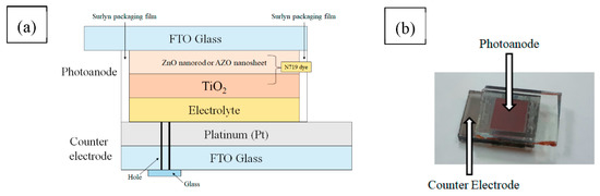
Figure 1.
(a) Schematic diagram of the dye-sensitized solar cell (DSSC) structure. (b) Photograph of the DSSC packaging.
2.5. Fabrication of Packaging for DSSCs in Parallel Connection
It was necessary to connect different active areas in parallel in order to fabricate the DSSC’s main area. First, the counter electrode drilled two holes. The purpose of the two holes was to facilitate the injection of the electrolyte. Then, the photoanode, the counter electrode, the Surlyn packaging film, and the small square normal glass were prepared. The hot press machine was used to heat press the Surlyn packaging film between the photoanode and the counter electrode at 100 °C for 60 s. Finally, the electrolytes were injected through the two holes into the component. A small square normal glass cap covered the two holes and epoxy to avoid electrolyte leakage This completed the production of the photoanode for DSSC 2 devices in parallel, and the schematic structure is shown in Figure 2a. In addition, we deposited the silver paste around the photoanodes by the doctor blade method for reducing the impedance between the connecting wire and transparent conductive oxide (TCO), as shown in Figure 2b.
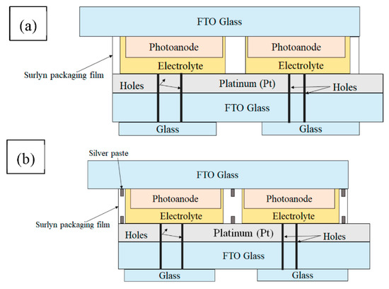
Figure 2.
Schematic diagram of (a) two parallel and (b) two parallel silver-grid DSSCs using zinc oxide (ZnO) nanorod photoanodes (one device exists in a silver-grid).
2.6. Instruments
The photovoltaic DSSC parameters were tested and recorded under an air mass of 1.5 global (AM 1.5 G) using a solar simulator (MFS-PV-Basic-HMT, New Taipei Taiwan). The Nyquist plots showing the interface impedance were generated using electrochemical impedance spectroscopy (BioLogic SP-150, Grenoble France) and the frequency range used for measurement ranged from 1 Mhz to 50 mHz. The absorbance level of the N719 dye was obtained using ultraviolet-visible spectroscopy (UV-vis) (LABOMED UVD-3500, Los Angeles USA).
3. Results and Discussion
3.1. Characterization of ZnO Nanorods and AZO Nanosheets
Figure 3 shows the X-ray diffraction (XRD) pattern of the ZnO nanorods and the AZO nanosheet deposition on the AZO seed layer. The AZO seed layer was deposited on pure glass. The sample showed the hexagonal wurtzite structure of ZnO (Joint Committee on Powder Diffraction Standards (JCPDS) card No. 36-1451) [29,30]. The ZnO nanorods were deposited on the AZO seed layer, which showed a stronger diffraction peak corresponding to the (002) plane, growing along the c-axis perpendicular to the substrate surface; weak (100), (101), (102), and (110) peaks were also observed. When Al(NO3)3·9H2O was added to the aqueous solution to form the AZO nanosheets, the reduced (002) peak intensity indicated that the AZO nanosheets did not exhibit an improved crystallinity [31,32]. Figure 4 shows the Field-Emission Scanning Electron Microscope (FE-SEM) forms for the ZnO nanorods and AZO nanosheets. Figure 4a shows the surface morphology of the ZnO nanorods. The thickness of ZnO nanorods was ~250 nm, as shown in Figure 4b. Figure 5a shows the surface morphology of the AZO nanosheets, and the thickness of the AZO nanosheets was ~241 nm, as shown in Figure 5b. Figure 6 shows the cross-view of the TiO2 layer with different photoanodes. Figure 6a,b indicate that the TiO2 film was deposited on ZnO nanorods or AZO nanosheets, and the thickness of TiO2 was ~16 μm, as shown in Figure 6c [33].
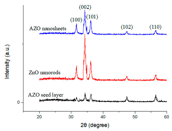
Figure 3.
X-ray diffraction (XRD) pattern of the ZnO nanorod and aluminum-doped zinc oxide (AZO) nanosheet deposition on the AZO seed layer.
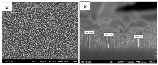
Figure 4.
Field-Emission Scanning Electron Microscope (FE-SEM) images of ZnO nanorods. (a) top view and (b) cross section.

Figure 5.
FE-SEM images of AZO nanosheets. (a) top view and (b) cross section.

Figure 6.
FE-SEM cross-view images of (a) ZnO nanorods/titanium dioxide (TiO2), (b) AZO nanosheets/TiO2, and (c) TiO2.
3.2. Ultraviolet-Visible Spectroscopy
ZnO is a material which can absorb dyes, and ZnO nanorods are a nanostructure which can increase the surface area. Therefore, when the photoanode is added to ZnO, which then becomes a double-layer structure, the amount of dye adsorption increases. Figure 7a shows characteristic peaks under ultraviolet-visible spectroscopy at ~500 nm. Figure 7a shows when the structures incorporating the ZnO nanorods or AZO nanosheets demonstrated enhanced dye absorption. Both the ZnO nanorods and AZO nanosheets displayed better dye absorption than the pure TiO2 structure. The ZnO nanorods and AZO nanosheets absorbed the dye, so they were deposited onto the FTO glass, which was also conducive to dye absorption. The dye sensitization effects on the ZnO nanorods/TiO2 and AZO nanosheets/TiO2 were compared. Figure 7a shows that for doped aluminum, the amount of dye absorption in AZO nanosheets decreases. Figure 8a shows that the values of the bandgap of the AZO seed layer, ZnO nanorods, and AZO nanosheet composite film were determined to be 3.39 eV, 3.33 eV, and 3.32 eV, respectively, by extrapolations of the linear regions of the plot to zero absorption. In addition, the bandgaps of TiO2 and FTO were 3.55 eV and 3.25 eV, respectively. Figure 8b shows the band gaps of ZnO nanorods/TiO2 and AZO nanosheets/TiO2 photoanodes for DSSCs [34].

Figure 7.
(a) Absorption spectra of different photoanodes against ruthenium-535 bis-TBA (N719) dye. (b) Nyquist plots of DSSCs with different photoanodes.
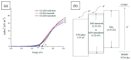
Figure 8.
(a) The relationship between (αhν)2 and energy for the AZO seed layer, ZnO nanorods, and AZO nanosheets films, respectively. (b) The band gaps of ZnO nanorods/TiO2 and AZO nanosheets/TiO2 photoanodes for DSSCs.
3.3. Electrochemical Impedance Spectroscopy (EIS)
Figure 7b shows the values generated by an equivalent circuit. The purpose of EIS is to measure the impedance (RS) between a connecting wire and a transparent conductive oxide (TCO), the interfacial impedance (R1) between an electrolyte and counter electrode, and the interfacial impedance (R2) between an electrolyte and a photoanode. This paper measured EIS by examining the changes in R2, to verify that adding AZO nanosheets and ZnO nanorods can improve electron transport.
As shown in Table 1, the R2 values for the TiO2, the ZnO nanorods/TiO2, and the AZO nanosheets/TiO2 were 76.43 Ω, 36.70 Ω, and 44.58 Ω, respectively. The R2 values for the ZnO nanorods/TiO2 and AZO nanosheets/TiO2 were smaller than that of the pure TiO2, and the results indicated that the AZO nanosheets and ZnO nanorods can improve electron transport when the electrons have a direct conduction pathway. Compared with the AZO nanosheets/TiO2 and ZnO nanorods/TiO2, the ZnO nanorods/TiO2 R2 value was smaller than the R2 for the AZO nanosheets/TiO2, verifying that the electron transport for the ZnO nanorods was superior to that of the AZO nanosheets. Impedance (RS) is defined as the wire resistance between a connecting wire and the transparent conductive oxide (TCO). When a layer of ZnO nanorods, or AZO nanosheets which facilitate electron transport, were deposited between the TCO and TiO2, Rs decreased, which resulted in an increase in the short-circuit current density (Jsc) [28], [35]. Compared with pure TiO2, the Rs of the ZnO nanorods/TiO2 and photoanode decreased from 27.00 Ω to 20.55 Ω, whereas that of the AZO nanosheets/TiO2 decreased from 27.00 Ω to 23.16 Ω.

Table 1.
Electrochemical impedance spectroscopy (EIS) spectra for the DSSCs with different photoanodes.
3.4. Photovoltaic Performance of DSSCs Based on ZnO Nanorods/TiO2 and AZO Nanosheets/TiO2
The ZnO nanorods and AZO nanosheets increased the current density and fill factor because these nanostructures had good electrical properties and improved electron transport to the FTO glass. Table 2 shows the photovoltaic performance parameters of the DSSC with ZnO nanorods/TiO2 and AZO nanosheet/TiO2 photoanodes. After the photoanode was added, the photovoltaic conversion efficiency (PCE) increased because electron transport was improved and dye absorption was enhanced. Improvement in electron transport was verified by EIS, and the increase in dye absorption was verified by ultraviolet-visible spectroscopy. Both of these factors facilitated an increase in PCE.
Table 2.
Photovoltaic performance parameters of the DSSCs with different photoanodes (the number of samples, n = 8).
Figure 9a shows J-V curves of TiO2, ZnO nanorods, and AZO nanosheets in DSSCs. The photoanodes were added as ZnO nanorods and AZO nanorods. Table 2 shows the results, which indicate that adding ZnO nanorods can increase the Jsc from 9.07 mA/cm2 to 10.91 mA/cm2, the Voc from 0.68 V to 0.70 V, and the PCE from 3.70% to 4.73%, respectively. In addition, this paper compared the ZnO nanorods/TiO2 with the AZO nanosheets/TiO2. The performance of the AZO nanosheets/TiO2 photoanodes was worse than the ZnO nanorods/TiO2 photoanodes. Figure 9b shows the incident photon-electron conversion efficiency (IPCE) of DSSCs with different photoanodes. We adopted IPCE to verify performance improvement. This result confirmed that the IPCE was improved after growing AZO nanosheets or ZnO nanorods on TiO2.

Figure 9.
(a) J-V curves of different photoanodes. (b) IPCE of DSSCs with different photoanodes.
3.5. Photovoltaic Performances of DSSCs in Parallel Connection
We fabricated DSSCs using a ZnO nanorod/TiO2 photoanode. When the active area became larger, the resistance became relatively larger, thereby reducing the photovoltaic conversion efficiency. DSSCs require a large active area, so we instead fabricated a parallel structure, hoping this would enable a type of applied modularization.
This study researched different active areas for the DSSCs using a ZnO nanorod/TiO2 photoanode. Table 3 and Figure 10 show the photovoltaic conversion efficiency of 4.73% for 0.64 cm2, 3.61% for 3.42 cm2, and 1.27% for 6.84 cm2. This shows that using a parallel structure can result in more effective use of larger DSSC areas. Figure 11a,b show the different parallel connections for DSSCs. In addition when fabricating the DSSCs, a parallel silver-grid device was produced, as shown in Figure 11c. Table 3 shows the results of using a parallel-grid device and Figure 12 shows a schematic of DSSCs with (a) two parallel and (b) two parallel-grid connections. The result of reducing the connection resistance is reflected in the fill factor. The fill factor is increased from 0.54 to 0.60. The main function of the grid is to increase electron transport, rather than increase the current density. The results indicated that the parallel silver-grid could reduce the connection resistance. The parallel-grid exhibits an enhanced photovoltaic conversion efficiency, with a PCE increase from 3.61% to 4.04%.
Table 3.
Photovoltaic property of DSSCs with different parallel (P) connections.

Figure 10.
J-V characteristics of different connections and active areas in DSSCs.
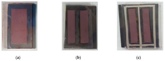
Figure 11.
Photographs of DSSCs with (a) single, (b) two parallel, and (c) two parallel silver-grid connections.
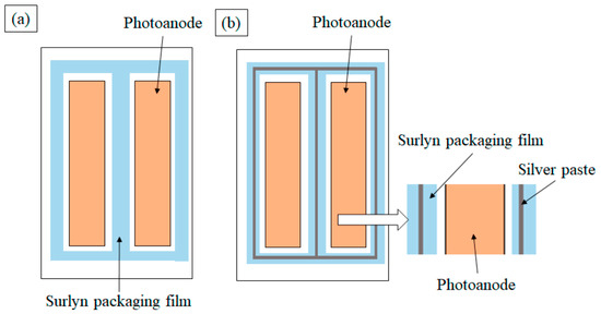
Figure 12.
Photographs of DSSCs with (a) two parallel and (b) two parallel silver-grid connections.
4. Conclusions
The properties of the DSSCs fabricated using ZnO nanorods/TiO2 and AZO nanosheets/TiO2 structures have been investigated. It has been shown here that the performance of the ZnO nanorod/TiO2 photoanode is better than that of the AZO nanosheet/TiO2 photoanode for DSSCs when measured by XRD, UV-vis, and EIS. Optimal parameters for the DSSCs were found using a ZnO nanorod/TiO2 photoanode, whereupon the photovoltaic conversion efficiency improved by 27.83%, from 3.70% to 4.73%. This improvement in the photovoltaic conversion efficiency was due to improvements in the short-circuit current density (Jsc). The photoanode of the DSSC used a ZnO nanorod/TiO2 double-layer structure, fabricated using the hydrothermal and doctor blade methods. Different combinations of DSSCs using alternate active areas and parallel connections were tested, and only relevant findings were reported. According to the experimental results, DSSCs in a parallel silver-grid can result in a higher photovoltaic conversion efficiency.
Author Contributions
Conceptualization, J.-C.C.; data curation, C.-C.K., J.-X.C., P.-Y.K., and G.-M.H.; formal analysis, C.-C.K., J.-X.C., C.-H.L., and Y.-H.N.; funding acquisition, J.-C.C. and Y.-H.N.; investigation, C.-C.K., J.-X.C., H.-H.C., and H.-H.H.; methodology, C.-C.K. and J.-X.C.; resources, J.-C.C. and Y.-H.N.; validation, C.-H.L., Y.-H.N., and P.-Y.K.; writing—original draft, C.-C.K.; writing—review & editing, J.-C.C., C.-H.L., and Y.-H.N.
Funding
This research and APC were funded by Taiwan [Ministry of Education and Ministry of Science and Technology] grant number [107-A055-8, MOST 107-2221-E-224-030 and MOST 108-2221-E-224-020].
Conflicts of Interest
The authors declare no conflicts of interest.
References
- Li, B.; Wang, L.; Kang, B.; Qiu, Y. Review of recent progress in solid-state dyesensitized solar cells. Sol. Energy Mater. Sol. Cells 2006, 90, 549–573. [Google Scholar] [CrossRef]
- Jiang, A.Y.; Xu, J.; Sun, Y.; Wei, C.; Wang, J.; Ke, D.; Li, X.; Yang, J.; Peng, X.; Tang, B. Day-ahead stochastic economic dispatch of wind integrated power system considering demand response of residential hybrid energy system. Appl. Energy 2017, 190, 1126–1137. [Google Scholar] [CrossRef]
- Chilkoti, V.; Bolisetti, T.; Balachandar, R. Climate change impact assessment on hydropower generation using multi-model climate ensemble. Renew. Energy 2017, 109, 510–517. [Google Scholar] [CrossRef]
- Tonini, D.; Vadenbo, C.; Astrup, T.F. Priority of domestic biomass resources for energy: Importance of national environmental targets in a climate perspective. Energy 2017, 124, 295–309. [Google Scholar] [CrossRef]
- Martin, S.S.; Chebak, A. Concept of educational renewable energy laboratory integrating wind, solar and biodiesel energies. Int. J. Hydrogen Energy 2016, 41, 21036–21046. [Google Scholar] [CrossRef]
- Donaldson, R.; Lord, E. Challenges for the implementation of the renewable heat incentive—An example from a school refurbishment geothermal scheme. Sustain. Energy Technol. Assess. 2014, 7, 30–33. [Google Scholar] [CrossRef]
- Nazeeruddin, M.K.; Baranoff, E.; Grätzel, M. Dye-sensitized solar cells: A brief overview. Sol. Energy 2011, 85, 1172–1178. [Google Scholar] [CrossRef]
- Yella, A.; Lee, H.W.; Tsao, H.N.; Yi, C.; Chandiran, A.K.; Nazeeruddin, M.K.; Diau, E.W.; Yeh, C.Y.; Zakeeruddin, S.M.; Grätzel, M. Porphyrin-sensitized solar cells with cobalt (II/III)-based redox electrolyte exceed 12 percent efficiency. Science 2011, 334, 629–634. [Google Scholar] [CrossRef]
- Qiu, J.; Guo, M.; Wang, X. Electrodeposition of hierarchical ZnO nanorod-nanosheet structures and their applications in dye-sensitized solar cells. ACS Appl. Mater. Interfaces 2011, 3, 2358–2367. [Google Scholar] [CrossRef]
- Balasingam, S.K.; Kang, M.G.; Jun, Y. Metal substrate based electrodes for flexible dyesensitized solar cells: Fabrication methods, progress and challenges. Chem. Commun. 2013, 49, 11457–11475. [Google Scholar] [CrossRef]
- Balasingam, S.K.; Kang, M.G.; Jun, Y. Improvement of dye-sensitized solar cells toward the broader light harvesting of the solar spectrum. Chem. Commun. 2013, 49, 1471–1487. [Google Scholar] [CrossRef] [PubMed]
- Obotowo, I.N.; Boot, I.B.; Eka, U.J. Organic sensitizers for dye sensitized solar cell(DSSC): Properties from computation, progress and future perspectivites. J. Mol. Struct. 2016, 1122, 80–87. [Google Scholar] [CrossRef]
- Lee, S.H.; Han, S.H.; Jung, H.S.; Shin, H.; Lee, J. Al-doped ZnO thin film: A new transparent conducting layer for ZnO nanowire-based dye-sensitized solar cells. J. Phys. Chem. C 2010, 114, 7185–7189. [Google Scholar] [CrossRef]
- Chou, J.C.; You, P.H.; Liao, Y.H.; Lai, C.H.; Chu, C.M.; Lin, Y.J.; Hsu, W.; Li, Y.C.C.; Nien, Y.H. Fabrication and photovoltaic properties of dye-sensitized solar cells based on graphene–TiO2 composite photoanode with ZnO nanowires view document. IEEE Trans. Semiconduct. 2017, 30, 531–538. [Google Scholar] [CrossRef]
- Chou, J.C.; Hsu, W.Y.; Liao, Y.H.; Lai, C.H.; Lin, Y.J.; You, P.H.; Chu, C.M.; Lu, C.C.; Nien, Y.H. Photovoltaic analysis of platinum counter electrode modified by graphene oxide and magnetic beads for dye-sensitized solar cell. IEEE Trans. Semiconduct. 2017, 30, 270–275. [Google Scholar] [CrossRef]
- Chou, J.C.; You, P.H.; Liao, Y.H.; Lai, C.H.; Chu, C.M.; Lin, Y.J.; Hsu, W.Y.; Li, C.C.; Nien, Y.H. An investigation on the photovoltaic properties of dye-sensitized solar cells based on Fe3O4-TiO2 composited photoanode. IEEE J. Electron. Dev. 2016, 4, 402–409. [Google Scholar]
- Yu, X.; Yu, X.; Zhang, J.; Hu, Z.; Zhao, G.; Zhao, Y. Effective light trapping enhanced near-UV/blue light absorption in inverted polymer solar cells via sol-gel textured Al-doped ZnO buffer layer. Sol. Energy Mater. Sol. Cells 2014, 121, 28–34. [Google Scholar] [CrossRef]
- Baradaran, M.; Ghodsi, F.E.; Bittencourt, C.; Llobet, E. The role of Al concentration on improving the photocatalytic performance of nanostructured ZnO/ZnO:Al/ZnO multilayer thin films. J. Alloys Compd. 2019, 788, 289–301. [Google Scholar] [CrossRef]
- Ajala, F.; Hamrouni, A.; Houas, A.; Lachheb, H.; Megna, B.; Palmisano, L.; Parrino, F. The influence of Al doping on the photocatalytic activity of nanostructured ZnO: The role of adsorbed water. Appl. Surf. SCI 2018, 445, 376–382. [Google Scholar] [CrossRef]
- Shivaraj, B.W.; Narasimha, M.H.N.; Krishna, M.; Satyanarayana, B.S. Effect of annealing temperature on the structural and optical properties of ZnO thin films prepared by RF magnetron sputtering. Procedia Mater. Sci. 2015, 10, 292–300. [Google Scholar] [CrossRef]
- Bhattacharya, J.; Peer, A.; Joshi, P.H.; Biswas, R.; Dalal, V.L. Blue photon management by inhouse grown ZnO:Al cathode for enhanced photostability in polymer solar cells. Sol. Energy Mater. Sol. Cells 2018, 179, 95–101. [Google Scholar] [CrossRef]
- Lee, C.P.; Lin, J.C.; Wang, Y.C.; Chou, C.Y.; Yeh, M.H.; Vittal, R.; Ho, K.C. Synthesis of hexagonal ZnO clubs with opposite faces of unequal dimensions for the photoanode of dye-sensitized solar cells. Phys. Chem. Chem. Phys. 2011, 13, 20999–21008. [Google Scholar] [CrossRef] [PubMed]
- Mou, J.; Zhang, W.; Fan, J.; Deng, H.; Cheng, W. Facile synthesis of ZnO nanobullets/nanoflakes and their applications to dye-sensitized solar cells. J. Alloys Compd. 2011, 509, 961–965. [Google Scholar] [CrossRef]
- Chang, J.; Ahmed, R.; Wang, H.; Liu, H.; Li, R.; Wang, P.; Waclawik, E.R. ZnO nanocones with high-Index {1011} facets for enhanced energy conversion efficiency of dye-sensitized solar cells. J. Phys. Chem. C 2013, 117, 13836–13844. [Google Scholar] [CrossRef]
- Chou, J.C.; Ko, C.C.; Kuo, P.Y.; Lai, C.H.; Nien, Y.H.; Chang, J.X. Fabrication of dye-sensitized solar cells using zinc oxide nanorod-modified titanium dioxide photoanode. IEEE Trans. Nanotechnol. 2019, 19, 553–561. [Google Scholar] [CrossRef]
- Kim, K.H.; Utashiro, K.; Abe, Y.; Kawamura, M. Structural properties of zinc oxide nanorods grown on Al-doped zinc oxide seed layer and their applications in dye-sensitized solar cells. Materials 2014, 7, 2522–2533. [Google Scholar] [CrossRef]
- Young, S.J.; Liu, Y.H. Field emission properties of Al-doped ZnO nanosheet based on field emitter device with UV exposure. RSC Adv. 2017, 7, 14219–14223. [Google Scholar] [CrossRef]
- Bella, F.; Gallia, S.; Piana, G.; Giacona, G.; Viscardi, G.; Grätzel, M.; Barolob, C.; Gerbaldi, C. Boosting the efficiency of aqueous solar cells: A photoelectrochemical estimation on the effectiveness of TiCl4 treatment. Electrochimica Acta 2019, 302, 31–37. [Google Scholar] [CrossRef]
- Craciun, P.V.; Garoi, F.; Staicu, A. Effect of annealing treatment on the structural and optical propertiesof AZO samples. Appl. Surf. SCI 2015, 352, 23–27. [Google Scholar]
- Yang, T.; Song, S.; Li, Y.; Xin, Y.; Du, G.; Lv, M.; Han, S. The enhanced conductivity and stability of AZO thin films with a TiO2 buffer layer. Physica B 2012, 407, 4518–4522. [Google Scholar] [CrossRef]
- Li, C.; Hou, S. Comparison of the photoluminescence properties of ZnO nanorods synthesized by multi-annealing and chemical bath deposition methods. ITE Trans. MTA 2016, 4, 320–325. [Google Scholar] [CrossRef][Green Version]
- Shrisha, B.V.; Bhat, S.; Kushavah, D.; Naik, K.G. Hydrothermal growth and characterization of Al-doped ZnO nanorods. Mater. Today 2016, 3, 1693–1701. [Google Scholar] [CrossRef]
- Kim, H.J.; Kim, J.H.; Kumar, C.S.S.P.; Punnoose, D.; Kim, S.K.; Gopi, C.V.V.M.; Rao, S.S. Facile chemical bath deposition of CuS nano peas like structure as a high efficient counter electrode for quantum-dot-sensitized solar cells. J. Electroanal. Chem. 2015, 739, 20–27. [Google Scholar] [CrossRef]
- Chou, J.C.; Chu, C.M.; Liao, Y.H.; Lai, C.H.; Lin, Y.J.; You, P.H.; Hsu, W.Y.; Lu, C.C.; Nien, Y.H. An investigation on the photovoltaic properties of dye-sensitized solar cells based on Fe3O4-TiO2 composited photoelectrode. IEEE J. Electron. Dev. 2016, 5, 32–39. [Google Scholar] [CrossRef]
- Dao, V.D.; Kim, S.H.; Choi, H.S.; Kim, J.H.; Park, H.O.; Lee, J.K. Efficiency enhancement of dye-sensitized solar cell using Pt hollow sphere counter electrode. J. Phys. Chem. C 2011, 115, 25529–25534. [Google Scholar] [CrossRef]
- Chou, H.T.; Lina, K.M.; Hsu, H.C. Fabrication of TiO2 compact layer precursor at various reaction times for dye sensitized solar cells. Microelectron. Reliab. 2015, 55, 2208–2212. [Google Scholar] [CrossRef]
- Ramasamy, E.; Lee, W.J.; Lee, D.Y.; Song, J.S. Portable, parallel grid dye-sensitized solar cell module prepared by screen printing. J. Power Sour. 2007, 165, 446–449. [Google Scholar] [CrossRef]


© 2019 by the authors. Licensee MDPI, Basel, Switzerland. This article is an open access article distributed under the terms and conditions of the Creative Commons Attribution (CC BY) license (http://creativecommons.org/licenses/by/4.0/).