Article

Heat-Absorbing Capacity of High-Heat-Flux Components in Nuclear Fusion Reactors

1
Department of Mechanical Engineering, Yonsei University, 50 Yonsei-ro, Seodaemun-gu, Seoul 03722, Korea
2
National Fusion Research Institute (NFRI), 169-148 Gwahak-ro, Yuseong-gu, Daejeon 34133, Korea
*
Author to whom correspondence should be addressed.
Energies 2019, 12(19), 3771; https://doi.org/10.3390/en12193771
Submission received: 26 August 2019 / Revised: 26 September 2019 / Accepted: 1 October 2019 / Published: 3 October 2019
(This article belongs to the Section J: Thermal Management)

Abstract

:
Nuclear fusion energy is a solution to the substitution of fossil fuels and the global energy deficit. However, among the several problems encountered for realizing a nuclear fusion reactor, the divertor presents difficulties due to the tremendous heat flux (~10 MW/m2) from high-temperature plasma. Also, neutrons produce additional heat (~17.5 MW/m3) from collisions with the materials’ atoms. This may lead to unexpected effects such as thermal failure. Thus, a comprehensive investigation on the divertor module is needed to determine the heat-absorbing capacity of the divertor module so to maintain the effect of incident heat flux. In this study, using an analytical approach and a simulation, the quantitative effect of heat generation on the thermophysical behavior, such as temperature and thermal stress, was analyzed while maintaining the incident heat flux. Then, a correlated equation was derived from the thermal design criteria, namely, the maximum thimble temperature and the safety factor at the vulnerable point. Finally, on the basis of the thermal design criteria, the heat-absorbing capacity of a nuclear fusion reactor in operating conditions was determined. This study contributes to the understanding of the divertor’s effects in nuclear fusion reactors for high-heat-flux and high-temperature applications.

1. Introduction

Nuclear fusion energy is a solution to the substitution of fossil fuels and the global energy deficit. For these reasons, several countries (China, European Union, India, Japan, Korea, Russia, and United states) have conducted research on the International Thermonuclear Experimental Reactor (ITER), which is the first fusion device maintaining fusion for long periods, and the demonstration reactor (DEMO), designed to prove the generation of electricity over several years [1]. However, there are several scientific/technological problems in developing nuclear fusion reactors, related to plasma instability [2], superconducting systems [3], blankets [4,5], and materials [6,7]. In particular, the divertor, which has the role of removing exhausted particles from the plasma and securing the shape of the plasma in the tokamak [1], is one of the most challenging components of a fusion plant, whose function is complicated by the requirement to dissipate large quantities of heat (~10 MW/m2). For this reason, investigations have been conducted on the thermal management of divertor modules by using water, helium, liquid lithium, and others [8,9].
For high-heat-flux components such as the divertor module, several cooling techniques, namely, pin fins [10,11,12], rib turbulators [13,14,15], and impingement jets [16,17,18], have been utilized for applications with various working fluids such as water [19,20], refrigerants [21,22], gas [23,24], and others [25,26,27]. Of the cooling techniques, impingement jet cooling is a powerful technique that achieves the highest heat transfer coefficient. In particular, the multi-array impingement jet (MAIJ), which applies the cooling performance of an impingement jet onto a larger area than that covered by a single impingement jet presented in Figure 1, has been adopted for the thermal management of divertors in nuclear fusion reactors because of its high heat transfer coefficient and thermal stability on a heated surface compared to other techniques [1,28,29,30]. In addition, helium is a prominent working fluid to manage the thermal load on the divertor module because of its high thermal conductivity (~0.23 W/mK) and chemical and neutronic inertness, despite its high pumping power. Thus, MAIJ with helium has been studied for several years to manage the high thermal load on the divertor module [31,32,33,34,35].
Recently, neutronics, which is the investigation of neutron effect on materials, has been the focus of several researchers connected with the irradiation of materials [36,37] and penetration depth [38,39]. In particular, the thermophysical behavior of a solid material upon neutron collision has been an issue of study for several years [1,40,41]. Researchers have found that, upon collision with tungsten (solid material) atoms, the neutron wall load (~2.3 MW/m2) causes volumetric heating (~17.5 MW/m3) in tungsten and additional thermal load on the nuclear fusion reactors [1]. The problem is that there is not enough thermal margin for the divertor, except for the incident heat flux (~10 MW/m2) from the high-temperature plasma. Additionally, it is impossible to measure the exact value of heat generation rate by neutron collision in full-scale nuclear fusion reactors because they are under construction or in the planning stage, which means that the additional volumetric heating can be changed. Furthermore, there have been a few studies on the heat transfer characteristics when the incident heat flux and the heat generated by neutrons affect the divertor in a nuclear fusion reactor. The additional thermal effect caused by neutronic heating, causes the divertor in a nuclear fusion reactor to undergo melting of the brazing material or thermal stress above the limits of allowable strength. Thus, a comprehensive investigation of the divertor system is required to determine not only the effect of the heat generation rate on the divertor module, but also the heat-absorbing capacity in relation to the incident heat flux.
Here, we investigated the effect of the heat generation rate on the thermophysical behavior of the divertor module and the heat-absorbing capacity considering the incident heat flux in relation to the design of the divertor module. We determined the correlation as a function of the incident heat flux and heat generation by combining mathematical results with those of a simulation, for the comprehensive understanding of heat transfer characteristics. The domain range of heat generation rate and heat flux was 0 to 140 MW/m3 and 4 to 12 MW/m2, respectively, on the basis of past research [1,42]. On the basis of previous work [42], we set the thermal design criteria, which are the maximum temperature of the thimble for relieving the difference of thermal expansion with respect to the tile, as shown in Figure 1, as well as the safety factor, considering thermal stress and yield strength in the divertor module. From the results of the simulation, we analyzed the thermophysical behavior of the MAIJ by changing the incident heat flux and heat generation by neutron heating. In addition, we calculated the heating contribution of the incident heat flux and neutron heating to the temperature and thermal stress of the divertor module. Finally, on the basis of the correlated equations of design elements such as maximum thimble temperature and thermal stress, we determined the heat-absorbing capacity corresponding to changes in the incident heat flux. This work is expected to improve our understanding of the thermophysical behavior of the divertor module in relation to the heat generation rate.

2. Material and Methods

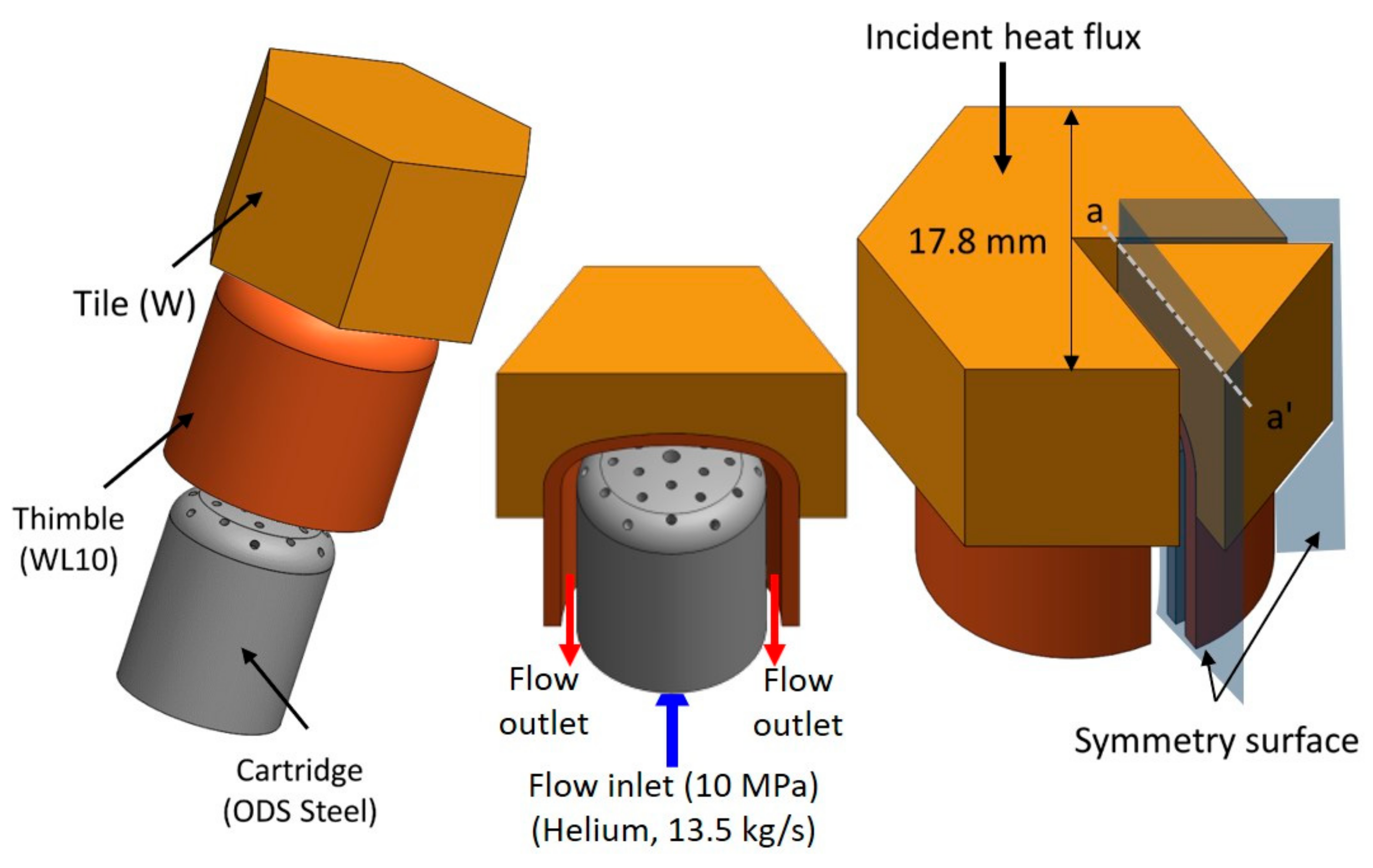
2.1. Geometry and Configuration of Multi-Array Impingement Jet Modules

Figure 1 shows the MAIJ of the divertor system in nuclear fusion reactors. A divertor unit cell with hexagonal shape consists of a tile, a thimble, and a cartridge [1,42]. The tile is made of tungsten, which has a high melting temperature (3422 °C) and a thermal conductivity of ~100 W/mK over 1000 °C. The width of the top surface was 17.8 mm, and the thickness ranged from 5 to 12 mm; the bottom of the tile had a concave shape. The thimble was installed below the tile and consisted of WL10, which has an operating windows between the ductile-brittle transition (600 °C), a recrystallization temperature (1300 °C) in the neutron-exposed condition, and intermediate thermal expansion coefficient (4.6 μm/m°C) between those of tungsten (4.0 μm/m°C) and of the cartridge (13.4 μm/m°C) at 20 °C with a thickness of 1 mm [43]. Between the tile and the thimble, a brazing material was used to fix the solid interface as a criterion of thermal design of the divertor module based on a melting temperature of 1050 °C [44]. Under the thimble, there was the cartridge with the MAIJ for cooling the divertor module. The MAIJ was composed of a center hole of 1 mm diameter and 24 holes of 0.6 mm diameter, along with four concentric arrays of six holes. Between the cartridge and the thimble, a space of 0.9 mm was used as the flow path after impinging on the heated surface toward the outlet.

2.2. Numerical Details

2.2.1. Modeling of the Thermo-Hydraulic Analysis

For the thermo-hydraulic simulation to investigate the thermal and fluid behaviors of the divertor module, we used a commercial code of CFX 15.0, which is widely utilized for similar investigations. We considered the continuity, momentum, and energy equations to evaluate the thermophysical behavior expressed as follow [45]:
· ρ v = 0
v · v = p ρ + μ + μ t 2 v
ρ v · U · k T + p · v = 0
where ρ , v , p , μ , μ t , U , k , and T are the helium density, velocity, pressure, dynamic viscosity, turbulent viscosity, internal energy, thermal conductivity, and temperature, respectively. The Reynolds Averaged Navier Stokes (RANS) equation was used to characterize turbulent phenomena in the fluid region. The shear stress transport model (SST model) was selected to study the multi-array impingement jet phenomena because an SST model is more effective in simulating results compared to the other turbulent models. In past research with k-ε and k-ω models, it was hard to estimate the adverse pressure gradient nearby the wall jet region; conversely, the SST model can predict the adverse pressure gradient in the wall jet region, thus increasing the accuracy of the simulation compared to the k-ε and k-ω models [46]. In addition, since there were some complex fluid phenomena near the impinging surface, we used a high-resolution scheme, which is second-order advection scheme to calculate the advection terms in finite volume methods [45], to capture the fluid behavior.
The thermo-hydraulic simulation was conducted on a segment corresponding to one-sixth of the divertor module, and the cut surface indicated symmetric conditions. The top surface of the tile was assumed to have a constant heat flux from 4 to 12 MW/m2 considering previous works [1,28,32,47]. The heat generation rate ranged from 0 to 140 MW/m3 on solid elements such as tile, thimble, and cartridge, which, according to several papers, corresponds to a wide range of heat generation rates [1,40,41]. The outer surface of the segment was set according to adiabatic conditions. The working fluid of the divertor module was the ideal gas of helium, whose properties were sourced from the NIST Webbook at a constant pressure of 10 MPa [48]. The inlet static pressure and temperature were set to 10 MPa and 540 °C, respectively. The total mass flow rate of the single divertor module was 13.5 g/s [42]. The thermophysical properties of tungsten and WL 10 were sourced from the ITER Materials Properties Handbook (MPH) [49]. The density and specific heats of tungsten and WL 10 are the same according to the reference, but thermal conductivity differs [50].
To study the thermal design of the high-heat-flux components, thermal stress is an important parameter by which to analyze the thermophysical behavior of the system. Thermal stress is caused by the thermal expansion of the divertor components owing to the presence of a temperature gradient in the system. In high-heat-flux components, thermal stress is a cause of thermal failure in the mechanical system. To analyze the thermal stress of the divertor module, we considered the temperature data calculated by thermal fluid analysis in the initial conditions of the thermo-mechanical analysis. The governing equation of thermal stress is expressed:
σ t h e r m a l   s t r e s s =   E 1 ν δ T s T r e f
where E, δ, ν, Ts, and Tref indicate the Young’s modulus of the solid, thermal expansion coefficient, Poisson’s ratio, temperature of the solid, and reference temperature, respectively. From the simulation, we inducted the equivalent stress (i.e., von Mises stress) for the evaluation of the system’s reliability in relation to the yield strength of the solid materials.
The geometry considered for the mechanical analysis was based only on the tile and the thimble, because the cartridge inside the divertor module does not affect the thermal stress. The elastic modulus (Young’s modulus), Poisson’s ratio, and coefficient of thermal expansion (CTE) were in accordance with ITER MPH [49]. In addition, we assumed that the elastic modulus and Poisson’s ratio of WL 10 are the same as those of tungsten. The cut surface was cyclic to reflect the hexagonal shape. A frictionless support condition was set on the bottom of the thimble, and the other parts could expand freely according to the temperature [1]. Furthermore, since the temperature range of the divertor module was wide, all properties were a function of the temperature.

2.2.2. Grid Formation and Validation

The grid for the thermohydraulic analysis consisted of an unstructured mesh generated by ANSYS Meshing, as shown in Figure 2a, with a grid number of 9.4 million to estimate the thermohydraulic behavior in the fluid path. To capture the thermo-fluidic behavior near the wall, the grid was concentrated around the solid–fluid interface. Moreover, the wall y plus value was considered near 1 on the impinging surface to capture the heat transfer characteristics. The numerical validation of the thermohydraulic analysis was compared to the reported experimental data [44,47], and the discrepancy was within 5.38% of the maximum temperature of the divertor module and 3.14% of the difference between the working fluid inlet and the outlet temperatures, as shown in in Figure 2b. The grid number of the thermomechanical analysis was 0.5 million, generated by ANSYS Meshing and determined by the grid independence test.

2.3. Analytical Approach

When a 1-D heat conduction equation is assumed for the analysis of the temperature behavior in a divertor module, this temperature has linear characteristics that enable the superposition of several effects on the temperature [51,52]. Thus, it can be separated from the factors that affect the temperature of the divertor module, such as heat flux and heat generation. On the basis of this assumption, we can express an arbitrary point temperature ( T p o i n t ) in the divertor module considering the variation of heat flux and temperature as follows:
T p o i n t = T f ,   i n + Δ T h e a t   f l u x + Δ T h e a t   g e n e r a t i o n
In Equation (5), this temperature can be divided into the three terms of reference temperature, temperature variation of heat flux, and heat generation. Δ T h e a t   f l u x is determined by the incident heat flux from the upper surface of the divertor module, and Δ T heat   generation is determined by the heat generation caused in the divertor module by neutronic heating. If the superposition of the factors is applied for the incident heat flux and heat generation, T point is affected by the increase in the temperature caused by the incident heat flux and heat generation rate. Considering the effect of the incident heat flux without heat generation, the thermal circuit of the divertor module [52] is applicable and expressed by the increase in temperature caused by heat flux in Equation (5) as follows:
T p o i n t   b y   h e a t   f l u x T r e f = q 1 h j e t + L t h i m b l e k t h i m b l e + L t i l e k t i l e = Δ T h e a t   f l u x
where q , R t o t , h j e t k t h i m b l e , L t h i m b l e , k t i l e , and L t i l e are the incident heat flux, total thermal resistance from the jet to an arbitrary point in the divertor module, heat transfer coefficient of the jet, thermal conductivity of the thimble, characteristic length of the thimble, thermal conductivity of the tile, characteristic length of the tile, and total thermal resistance of the specific point, respectively. The reference temperature in the study was the fluid inlet temperature ( T f ,   i n ) because it was a factor used to determine the temperature in the impingement jet system in previous works [42,44,53]. The heat transfer coefficient due to the impingement jet is a function of the Reynolds number, which expresses the mass flow rate of the jet [42,52]. The conduction terms of the thimble and tile are minor terms compared to the heat transfer coefficient term in the operating domain of the study. Thus, by analyzing the local temperature at the same mass flow rate and a specific point, in Equation (6), it is recognized that the temperature is a function of the heat flux, which is the total thermal resistance up to the specific point. Additionally, on the basis of the temperature related to the incident heat flux, the total thermal resistance derived from the slope of the temperature at the specific point can be determined.
In Equation (5), the third term regarding the increase in temperature caused by the heat generation rate is expressed by the energy balance between heat generation and dissipation at the interface of thimble and working fluid. On the basis of this consideration, we describe the energy balance as follows:
Q h e a t   g e n e r a t i o n =   q V = h j e t A j e t T j e t T r e f =   Q D i s s i p a t i o n
where Q, ρ , c p , V , T are the density, specific heat, volume, and temperature, respectively. The subscript “jet” means the interfacial area at the bottom of the thimble surface. Most of the heat transfer phenomena occur at the interfacial area by intersecting the bottom of the tile surface, thus the temperature is expressed on the impinged surface as follows:
T j e t =   T r e f + q V h j e t A j e t
In Equation (8), the heat transfer coefficient of the impinged surface is calculated by the simulation. On the basis of the temperature on the impinged surface, the energy balance in the solid part is considered to obtain the temperature of an arbitrary point. By assuming 1-D conduction corresponds to the deduction of the increase in temperature by heat flux, the equation is expressed by Fourier’s law as follows:
k A d T d x k A T j e t T p o i n t   b y   h e a t   g e n e r a t i o n L x = q A L x
where Lx and A express the distance from the interfacial surface and the area of conduction heat transfer inside the solid domain, respectively. Integrating Equation (9) with Equation (8), Equation (10) is obtained, considering the increase in temperature by heat generation as follows:
T p o i n t   b y   h e a t   g e n e r a t i o n T r e f = q V h j e t A j e t + L x k = Δ T h e a t   g e n e r a t i o n
Based on Equations (6) and (10), the temperature at the arbitrary point is finally obtained as follows:
T p o i n t = T f ,   i n + R t o t q + V h j e t A j e t + L x k q =   T f ,   i n + α q * + β q * *
q * = q / 10 M W m 2 ,   q * * = q / 17.5 M W m 3
where α, β, q*, and q** are non-dimensionalized terms to express the ratio of heat flux to heat generation magnitude compared to the reference heat flux and heat generation values [1]. From Equation (11), the continuous wide range of thermophysical behavior can be estimated using the correlated equation with the simulated data, obtaining the design guidelines of a helium-cooled divertor.

3. Results and Discussions

3.1. Heat Generation Effect on the Maximum Thimble Temperature

Figure 3a presents the temperature distribution in the divertor module. Since we can infer that the shortest heat flow path for the same amount of heat flux results in higher temperature at the end of the heat flow path, we can recognize that the maximum thimble temperature occurs at the top center of the thimble. To evaluate the heat-absorbing capacity with respect to the change in heat flux, we analyzed the temperature behavior in the divertor module. In the divertor module, there were three design limits related to the temperature, namely, the melting point of the tile and thimble (~3422 °C) [54], the recrystallization temperature of the thimble (~1300 °C), and the brazing temperature of STEMET® (1050 °C) between the tile and the thimble [44]. From the design limits, the brazing temperature at the lowest value represented an important criterion for the thermal design of the divertor module. In addition, the design temperature of the brazed region was determined according to the maximum thimble temperature, because the brazed part reached the highest temperature. Thus, we found that the local temperature at the top center of the thimble can represent the main design criterion of the divertor module [42].
In Equation (11), we presented the linear relation between the normalized heat generation rate and incident heat flux and the local temperature; α in Equation. (11) is the temperature increase due to the heat flux and is determined by the thermal conductivity and heat flow length. This linearity was already explained in a previous work [42], since the heat flow length was the same according to the analysis of the maximum thimble temperature, and the thermal conductivity was almost constant, within 5.8% in the range from 500 to 1050 °C in the study. Interestingly, β in Equation (11), which represents the effect of normalized heat generation on the increase in temperature, is also linearly proportional to the temperature at the maximum thimble temperature. It means that our assumption of 1-D equation and constant properties is reliable for the estimation of the temperature in the helium-cooled divertor module. On the basis of the simulation results and the analytical approach, we could deduce the coefficients α and β in Equation (11). For α, we used the slope of linear fitting of the simulation data in the case of lack of heat generation because it is reasonable to analyze only the heat flux effect to determine the coefficient.
Consequently, α was 431.4 °C on the basis of the results of the cases without heat generation. In addition, β was determined using the averaged heat transfer coefficient on the impinged surface, the ratio between volume and impinged surface, the averaged thermal conductivity in the thimble, and the distance between the impinged surface and the point of maximum thimble temperature. The averaged heat transfer coefficient on the impinged surface was 36,214.6 W/m2K, which was area-averaged on the intersected surface by the bottom of the tile. The ratio of volume and interfacial area was 8.75 mm in this study. The averaged thermal conductivity was 99 W/mK, which was determined for the range of 540 to 1400 °C. In addition, the distance was 1 mm, extracted from the geometry of the divertor module. On the basis of these values, β was 5.77 °C. Regarding the values of α and β in Equation (11), firstly, we inferred the contribution of maximum thimble temperature increase in terms of heat flux and heat generation. The increase in temperature was 431.4 °C per heat flux of 10 MW/m2 and 5.77 °C per heat generation of 17.5 MW/m3. In addition, the heat flux of 0.13 MW/m2 gave the same contribution as the heat generation of 17.5 MW/m3. This means that the reliable heat flux was reduced by the heat generated by neutron heating, which we should consider, as it might affect thermal design point. Using the coefficients α and β, we drew the correlation line from 4 to 12 MW/m2 of heat flux and from 0 to 140 MW/m3 of heat generation in Figure 3b. As shown in Figure 3b, the discrepancy between the simulation results and those form the correlated equation was within 2%, and the correlation supported the expression of the temperature behavior of the divertor module according to the changes in heat generation and heat flux. Therefore, we judged that we can use the correlation results to deduce the heat-absorbing capacity on the basis of the changes in heat flux for the thermal design of the divertor module.

3.2. Thermomechanical Behavior Caused by Heat Generation Rate

In high-heat-flux applications, thermal stress should be considered in the thermal design because it causes thermal failure due to harsh temperature gradients in the system [55,56]. In addition, thermal stress should be considered with the yield strength in the elastic region, since thermal stress alone cannot characterize vulnerable points in a mechanical system [42]. Thus, we analyzed thermal stress and evaluated the integrated factor considering the yield strength in the divertor module. Figure 4a shows the equivalent stress (von Mises stress) distribution of the divertor module in the study. As shown in Figure 4a, we could guess three vulnerable points: top of the tile (low stress and yield strength), periphery of the tile and thimble connection (high stress and yield strength), and inner curved surface of the thimble (high stress and yield strength). Among these three vulnerable points, in a previous work [42], we showed that the most vulnerable one in the divertor is the inner surface of the thimble because it is the location of the highest stress and because the thimble material has a lower yield strength than the tile in the temperature range considered. Thus, we analyzed the thermomechanical behavior in the region of the inner curved surface.
Figure 4b shows the thermal stress results at the vulnerable point. In Figure 4b, the thermal stress is linearly proportional to the heat generation and heat flux in the simulation. This is because the governing Equation (4) is based on the difference between the solid’s temperature and the reference temperature. The first term in Equation (4), which is a function of elastic modulus, Poisson’s ratio, and thermal expansion coefficient, is almost constant (within 7.3%) in the temperature range from 500 to 1700 °C. This means that the thermal stress is a linear function of the solid’s temperature, because the reference temperature is constant in this study. Since the temperature at the vulnerable point is also linearly proportional to the heat flux, we inferred that the thermal stress is also linearly proportional to the heat flux [42]. Thus, we determined the correlation of thermal stress with respect to the temperature at the vulnerable point as follows:
T s t r e s s ,   p o i n t = T f ,   i n + α q * + β q * *
σ s t r e s s ,   p o i n t = a + b q * + c q * *
where α′, β′, a, b, and c are correlation coefficients from the simulation results covering the operating domain in the study. From the linear curve fitting of the simulation results in the no-heat-generation case at the vulnerable point, the correlated coefficients of α′ and β′ were 215.9 °C and 4.2 °C. On the basis of Equation (13) and the thermal stress results at the vulnerable point, the coefficients a, b, and c were –78.89, 466.68, and 5.51 MPa, respectively. From the correlation, in the design point of thermal stress, the heat flux of 0.12 MW/m2 was converted into a heat generation of 17.5 MW/m3. As shown in Figure 4b, the maximum discrepancy between the simulation results and the correlation was 5% for the area studied. This shows that the correlation analysis is valid for the investigation of the thermo-mechanical behavior of the divertor module.
As mentioned above, to evaluate the thermomechanical reliability of the divertor module, we should integrate the thermal stress with the yield strength. In this study, we used the concept of safety factor expressed as follows:
N =   σ y i e l d   s t r e n g t h q * , q * * / σ c a l c u l a t e d   s t r e s s q * , q * *
where both yield strength and calculated stress are functions of the temperature expressed as a function of normalized heat flux and heat generation. Figure 5 shows the safety factor at the vulnerable point with changes in heat generation. In Figure 5, the safety factor decreases gradually with increasing heat generation, since the increase in heat generation causes an increase in temperature, increase in thermal stress, and decrease in yield strength. With the design criterion of the safety factor set as 1.1 in the ideal conditions [57], a heat flux over 12 MW/m2 makes it difficult for the divertor module to manage a high heat load. This means that, in terms of thermophysical behavior, an incident heat flux over 10 MW/m2 deteriorates the divertor module, despite the lack of heat generation. Additionally, the discrepancy of between the results of the correlated equation and the simulation results was within 10%. Therefore, we evaluated the heat-absorbing capacity with changes in heat flux using Equations (11) and (15).

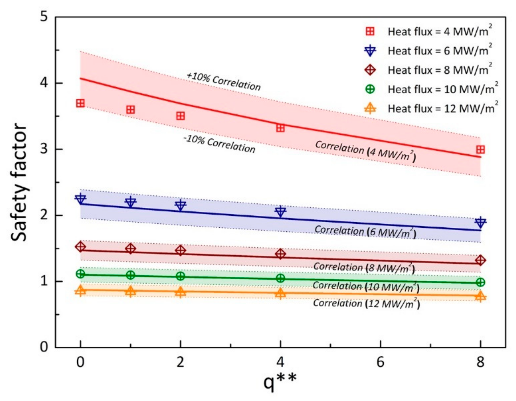
3.3. Heat-Absorbing Capacity for the Satisfaction of System Reliability

Figure 6 shows the thermal design map of maximum thimble temperature with changes in the normalized heat flux (q*) (0–1.4) and heat generation (q**) (0–100) based on Equation (11). As shown in Figure 6, the temperature has a linearly proportional trend with respect to both heat generation and heat flux. On the basis of the temperature criteria, the red-dashed line represents the thermal design guideline of the maximum thimble temperature in the divertor module. In contrast, in Figure 7, the graph trend has a curved shape according to by Equation (15), since the yield strength is a function of heat generation and heat flux, and thermal stress is a linear function of heat generation and heat flux. On the basis of the safety factor criteria of 1.1 in the ideal conditions [57], the region with satisfying reliable operation is also characterized by low heat generation and low heat flux. To determine the heat-absorbing capacity for the thermal design of the divertor, we deduced the results of Figure 6 and Figure 7.
Figure 8 expresses the heat-absorbing capacity with changes in heat flux over the whole range of the study. As shown in Figure 8, we determined the different heat-absorbing capacities with respect to heat generation related to the maximum thimble temperature and safety factor. Using curve fitting, we derived the equation for the line of the margin. At the maximum thimble temperature, the equation of heat-absorbing capacity can be expressed as follows:
q m a r g i n ,   t e m p . * * = 74.71 q * + 88.32
Equation (16) means that the heat-absorbing capacity of 1545.6 MW/m3 (q** = 88.32) was allowed at 0 MW/m2, and no increase of the heat-absorbing capacity is possible for a heat flux higher than 11.82 MW/m2 (q* = 1.182). In a similar manner, we calculated the heat-absorbing capacity in relation to the safety factor of 1.1 as follows [53]:
q m a r g i n ,   s a f e t y   f a c t o r * * = 80.50 q * + 80.69
Equation (17) shows that the heat-absorbing capacity of 1408.17 MW/m3 (q** = 80.69) was allowed at 0 MW/m2 and was effective for a heat flux up to 10.002 MW/m2. Consequently, the satisfying region in Figure 8 has a favorable heat-absorbing capacity, when considering maximum thimble temperature and safety factor at the vulnerable point. Furthermore, of primary concern in the analysis of the heat-absorbing capacity is the safety factor of the thimble for the thermal design of the divertor.

4. Conclusions

This study investigated the effect of the additional heat generation caused by neutronic collision on the divertor module and determined the heat-absorbing capacity considering the incident heat flux, using an analytical approach and a numerical simulation. On the basis of a previous study, the design criteria, namely, the maximum thimble temperature, which is related to the brazing material between the tile and the thimble, and the safety factor of the thimble at the vulnerable point were evaluated, together with thermal stress and yield strength. From the analytical approach and simulation, correlation equations were used to determine the design criteria and deduce the heat-absorbing capacity. From these results, firstly, the maximum thimble temperature and thermal stress appeared to be linearly proportional to both the heat generation and the heat flux according to the analytical approach. This can help to understand the heat transfer characteristics in the harsh conditions of the nuclear fusion reactor. Secondly, the effect of heat flux on the thimble temperature was much bigger than the effect of the heat generation, because the reported values of heat generation caused by neutron collision were lower than those of the incident heat flux. However, around the steady-state conditions of incident heat flux (10 MW/m2), the small amount of heat generation affected the heat-absorbing capacity seriously. Thirdly, a thermal design map is suggested to overcome the limitation of some of the simulation data, because the margin of the heat-absorbing capacity is meager in the real conditions of the nuclear fusion reactor. Finally, the heat-absorbing capacity using the heat flux of the helium-cooled divertor module was deduced. The presented approach is meant for research on the divertor module in nuclear fusion reactors, as well as for various high-heat-flux applications.

Author Contributions

Conceptualization, N.L., B.S.K. and H.H.C.; Investigation, N.L., B.S.K., H.M. and J.-S.L.; Supervision, H.H.C.; Writing—original draft, N.L.; Writing—review & editing, B.S.K., H.M., J.-S.L. and H.H.C.

Funding

This work was funded by the Human Resources Development program (No. 20174030201720) of the Korea Institute of Energy Technology Evaluation and Planning (KETEP) grant funded by the Korea government Ministry of Trade, Industry and Energy.

Acknowledgments

This work was supported by the Human Resources Development program (No. 20174030201720) of the Korea Institute of Energy Technology Evaluation and Planning (KETEP) grant funded by the Korea government Ministry of Trade, Industry and Energy.

Conflicts of Interest

The authors declare no conflict of interest.

References

  1. Norajitra, P. Divertor Development for a Future Fusion Power Plant; KIT Scientific Publishing: Karlsruhe, Germany, 2014. [Google Scholar]
  2. Bagryansky, P.A.; Gospodchikov, E.D.; Ivanov, A.A.; Lizunov, A.A.; Kolesnikov, E.Y.; Konshin, Z.E.; Korobeynikov, O.A.; Kovalenko, Y.V.; Maximov, V.V.; Murakhtin, S.V.; et al. Studies of Plasma Confinement and Stability in a Gas Dynamic Trap: Results of 2016-2018. Plasma Fus. Res. 2019, 14, 2402030. [Google Scholar] [CrossRef]
  3. Tamura, H.; Goto, T.; Yanagi, N.; Miyazawa, J.; Tanaka, T.; Sagara, A.; Ito, S.; Hashizume, H. Effect of coil configuration parameters on the mechanical behavior of the superconducting magnet system in the helical fusion reactor FFHR. Fus. Eng. Des. 2019, in press. [Google Scholar] [CrossRef]
  4. Lei, M.; Song, Y.; Ye, M. Thermal hydraulic analysis of the HECLIC blanket breeder unit for CFETR. Int. J. Energy Res. 2015, 39, 370–376. [Google Scholar] [CrossRef]
  5. Lei, M.; Xu, S.; Guo, C.; Liu, S.; Song, Y.; Lu, K.; Pei, K.; Xu, K. Design and thermal-hydraulic evaluation of helium-cooled ceramic breeder blanket for China fusion engineering test reactor. Int. J. Energy Res. 2018, 42, 1657–1663. [Google Scholar] [CrossRef]
  6. Tejado, E.; Müller, A.V.; You, J.H.; Pastor, J.Y. Evolution of mechanical performance with temperature of W/Cu and W/CuCrZr composites for fusion heat sink applications. Mater. Sci. Eng. A 2018, 712, 738–746. [Google Scholar] [CrossRef] [Green Version]
  7. Coenen, J.W.; Mao, Y.; Sistla, S.; Müller, A.V.; Pintsuk, G.; Wirtz, M.; Riesch, J.; T Hoeschen, A.T.; Terraa, A.; You, J.H.; et al. Materials development for new high heat-flux component mock-ups for DEMO. Fusion Eng. Des. 2019, 146, 1431–1436. [Google Scholar] [CrossRef]
  8. You, J.; Visca, E.; Barrett, T.; Böswirth, B.; Crescenzi, F.; Domptail, F.; Fursdon, M.; Gallay, F.; Ghidersa, B.; Greuner, H.; et al. European divertor target concepts for DEMO: Design rationales and high heat flux performance. Nucl Mat. Energy 2018, 16, 1–11. [Google Scholar] [CrossRef]
  9. Rindt, P.; Morgan, T.W.; Jaworski, M.A.; Cardozo, N.J.L. Power handling limit of liquid lithium divertor targets. Nucl. Fusion 2018, 58, 104002. [Google Scholar] [CrossRef] [Green Version]
  10. Yuan, W.; Zhao, J.; Tso, C.P.; Wu, T.; Liu, W.; Ming, T. Numerical simulation of the thermal hydraulic performance of a plate pin fin heat sink. Appl. Eng. 2012, 48, 81–88. [Google Scholar] [CrossRef]
  11. Zhao, J.; Huang, S.; Gong, L.; Huang, Z. Numerical study and optimizing on micro square pin-fin heat sink for electronic cooling. Appl. Eng. 2016, 93, 1347–1359. [Google Scholar] [CrossRef]
  12. Park, J.S.; Kim, K.M.; Lee, D.H.; Cho, H.H.; Chyu, M. Heat Transfer in Rotating Channel with Inclined Pin-Fins. J. Turbomach. 2011, 133, 021003. [Google Scholar] [CrossRef]
  13. Kim, K.M.; Lee, D.H.; Cho, H.H. Pressure drop and thermal performance in rotating two-pass ducts with various cross rib arrangements. Heat Mass Trans. 2007, 44, 913–919. [Google Scholar] [CrossRef]
  14. Kim, K.M.; Lee, H.; Kim, B.S.; Shin, S.; Lee, D.H.; Cho, H.H. Optimal design of angled rib turbulators in a cooling channel. Heat Mass Trans. 2009, 45, 1617–1625. [Google Scholar] [CrossRef]
  15. Ma, T.; Wang, Q.-W.; Zeng, M.; Chen, Y.-T.; Liu, Y.; Nagarajan, V. Study on heat transfer and pressure drop performances of ribbed channel in the high temperature heat exchanger. Appl. Energy 2012, 99, 393–401. [Google Scholar] [CrossRef]
  16. Han, B.; Goldstein, R. Jet-Impingement Heat Transfer in Gas Turbine Systems. Ann. N. Y. Acad. Sci. 2001, 934, 147–161. [Google Scholar] [CrossRef] [PubMed]
  17. Hong, S.K.; Lee, D.H.; Cho, H.H. Effect of jet direction on heat/mass transfer of rotating impingement jet. Appl. Therm. Eng. 2009, 29, 2914–2920. [Google Scholar] [CrossRef]
  18. Wang, B.; Lin, D.; Xie, Q.; Wang, Z.; Wang, G. Heat transfer characteristics during jet impingement on a high-temperature plate surface. Appl. Therm. Eng. 2016, 100, 902–910. [Google Scholar] [CrossRef]
  19. Whelan, B.P.; Kempers, R.; Robinson, A.J. A liquid-based system for CPU cooling implementing a jet array impingement waterblock and a tube array remote heat exchanger. Appl. Eng. 2012, 39, 86–94. [Google Scholar] [CrossRef]
  20. Wu, S.-J.; Shin, C.H.; Kim, K.M.; Cho, H.H. Single-phase convection and boiling heat transfer: Confined single and array-circular impinging jets. Int. J. Multiph. Flow 2007, 33, 1271–1283. [Google Scholar] [CrossRef]
  21. Shin, C.H.; Kim, K.M.; Lim, S.H.; Cho, H.H. Influences of nozzle-plate spacing on boiling heat transfer of confined planar dielectric liquid impinging jet. Int. J. Heat Mass Trans. 2009, 52, 5293–5301. [Google Scholar] [CrossRef]
  22. Shin, S.; Choi, G.; Kim, B.S.; Cho, H.H. Flow boiling heat transfer on nanowire-coated surfaces with highly wetting liquid. Energy 2014, 76, 428–435. [Google Scholar] [CrossRef]
  23. Tahat, M.; Kodah, Z.; Jarrah, B.; Probert, S. Heat transfers from pin-fin arrays experiencing forced convection. Appl. Energy 2000, 67, 419–442. [Google Scholar] [CrossRef]
  24. Bi, C.; Tang, G.H.; Tao, W.Q. Heat transfer enhancement in mini-channel heat sinks with dimples and cylindrical grooves. Appl. Eng. 2013, 55, 121–132. [Google Scholar] [CrossRef]
  25. Yang, J.; Pais, M.R.; Chow, L.C. Critical Heat Flux Limits in Secondary Gas Atomized Liquid Spray Cooling. Exp. Heat Trans. 1993, 6, 55–67. [Google Scholar] [CrossRef]
  26. Hsieh, S.-S.; Fan, T.-C.; Tsai, H.-H. Spray cooling characteristics of water and R-134a. Part I: Nucleate boiling. Int. J. Heat Mass Trans. 2004, 47, 5703–5712. [Google Scholar] [CrossRef]
  27. Kim, J. Spray cooling heat transfer: The state of the art. Int. J. Heat Fluid Flow. 2007, 28, 753–767. [Google Scholar] [CrossRef]
  28. Weathers, J.B.; Crosatti, L.; Kruessmann, R.; Sadowski, D.L.; Abdel-Khalik, S.I. Development of modular helium-cooled divertor for DEMO based on the multi-jet impingement (HEMJ) concept: Experimental validation of thermal performance. Fus. Eng. Des. 2008, 83, 1120–1125. [Google Scholar] [CrossRef]
  29. Rader, J.D.; Mills, B.H.; Sadowski, D.L.; Yoda, M.; Abdel-Khalik, S.I. Verification of thermal performance predictions of prototypical multi-jet impingement helium-cooled divertor module. Fus. Sci. Technol. 2013, 64, 282–287. [Google Scholar] [CrossRef]
  30. Jung, H.-Y.; Kim, K.-Y. Thermal-hydraulic performance of a multiple jet cooling module with a concave dimple array in a helium-cooled divertor. Fus. Eng Des. 2017, 114, 102–112. [Google Scholar] [CrossRef]
  31. Hermsmeyer, S.; Kleefeldt, K. Review and Comparative Assessment of Helium-Cooled Divertor Concepts; Forschungszentrum: Karlsruhe, Germany, 2001. [Google Scholar]
  32. Ovchinnikov, I.; Giniyatulin, R.; Ihli, T.; Janeschitz, G.; Komarov, A.; Kruessmann, R.; Kuznetsov, V.; Mikhailov, S.; Norajitra, P.; Smirnov, V. Experimental study of DEMO helium cooled divertor target mock-ups to estimate their thermal and pumping efficiencies. Fus. Eng. Des. 2005, 73, 181–186. [Google Scholar] [CrossRef]
  33. Krüßmann, R.; Messemer, G.; Zinn, K. Overview of Thermohydraulic Simulations for the Development of a Helium-Cooled Divertor; Forschungszentrum: Karlsruhe, Germany, 2008. [Google Scholar]
  34. Lee, N.; Lim, J.-S.; Ghidersa, B.; Cho, H.H. Nozzle-to-target distance effect on the cooling performances of a jet-impingement helium-cooled divertor. Fus. Eng Des. 2018, 136, 803–808. [Google Scholar] [CrossRef]
  35. Lim, J.-S.; Lee, N.; Ghidersa, B.-E.; Cho, H.H. Enhancement of cooling performance of a helium-cooled divertor through the addition of rib structures on the jet-impingement area. Fus. Eng. Des. 2018, 136, 655–660. [Google Scholar] [CrossRef]
  36. Materna-Morris, E.; Lindau, R.; Schneider, H.-C.; Möslang, A. Tensile behavior of EUROFER ODS steel after neutron irradiation up to 16.3 dpa between 250 and 450 °C. Fus. Eng. Des. 2015, 98–99, 2038–2041. [Google Scholar] [CrossRef]
  37. Hasegawa, A.; Fukuda, M.; Yabuuchi, K.; Nogami, S. Neutron irradiation effects on the microstructural development of tungsten and tungsten alloys. J. Nucl. Mat. 2015, 471, 175–183. [Google Scholar] [CrossRef]
  38. Gilbert, M.; Dudarev, S.; Zheng, S.; Packer, L.; Sublet, J.-C. An integrated model for materials in a fusion power plant: Transmutation, gas production, and helium embrittlement under neutron irradiation. Nucl. Fus. 2012, 52, 083019. [Google Scholar] [CrossRef]
  39. Batistoni, P.; Fischer, P.U.; Ochiai, K.; Petrizzi, L.; Seidel, K.; Youssef, M. Neutronics and nuclear data issues in ITER and their validation. Fus. Eng. Des. 2008, 83, 834–841. [Google Scholar] [CrossRef]
  40. Serikov, A.; Fischer, U.; Große, D.; Heidinger, R.; Spah, P.; Strauß, D. Nuclear-safety-related and shielding analyses of the ITER quasi-optical ECH launcher. IEEE Trans. Plasma Sci. 2010, 38, 224–231. [Google Scholar] [CrossRef]
  41. Serikov, A.; Fischer, U.; Grosse, D. High performance parallel Monte Carlo transport computations for ITER fusion neutronics applications. Prog. Nucl. Sci. Tech. 2011, 2, 294–300. [Google Scholar] [CrossRef]
  42. Lee, N.; Kim, B.S.; Kim, T.; Bae, J.-Y.; Cho, H.H. Thermal design of helium cooled divertor for reliable operation. Appl. Eng. 2017, 110, 1578–1588. [Google Scholar] [CrossRef]
  43. Norajitra, P.; Giniyatulin, R.; Ihli, T.; Janeschitz, G.; Karditsas, P.; Krauss, W.; Kruessmann, R.; Kuznetsov, V.; Maisonnier, D.; Mazul, I.; et al. European development of He-cooled divertors for fusion power plants. Nucl. Fus. 2005, 45, 1271–1276. [Google Scholar] [CrossRef]
  44. Končar, B.; Norajitra, P.; Oblak, K. Effect of nozzle sizes on jet impingement heat transfer in He-cooled divertor. Appl. Therm. Eng. 2010, 30, 697–705. [Google Scholar] [CrossRef] [Green Version]
  45. ANSYS. ANSYS CFX-Solver Theory Guide; ANSYS: Canonsburg, PN, USA, 2013. [Google Scholar]
  46. Zuckerman, N.; Lior, N. Jet Impingement Heat Transfer: Physics, Correlations, and Numerical Modeling. Adv. Heat Transf. 2006, 39, 565–631. [Google Scholar]
  47. Končar, B.; Draksler, M.; Oblak, K.; Norajitra, P.; Widak, V. Numerical investigation of multiple-jet cooling concept for helium cooled divertor. In Proceedings of the International Conference Nuclear Energy for New Europe, Portoroz, Slovenia, 8–11 September 2008. [Google Scholar]
  48. NIST. Thermophysical Properties of Fluid Systems. Available online: http://webbook.nist.gov/chemistry/fluid/ (accessed on 1 October 2018).
  49. Davis, J.; Smith, P. ITER material properties handbook. J. Nucl. Mat. 1996, 233, 1593–1596. [Google Scholar] [CrossRef]
  50. Kruessmann, R.; Norajitra, P. Conceptual Design of a He-Cooled Divertor with Integrated Flow and Heat Transfer Promoters (PPCS Subtask TW3-TRP-001-D2): Part II: Detailed Version; Forschungszentrum: Karlsruhe, Germany, 2004. [Google Scholar]
  51. Kreyszig, E.; Norminton, E.J. Advanced Engineering Mathematics; John Wiley: New York, NY, USA, 2006. [Google Scholar]
  52. Çengel, Y.A.; Ghajar, A.J. Heat and Mass Transfer: Fundamentals & Applications; McGraw-Hill: New York, NY, USA, 2011. [Google Scholar]
  53. Hwang, S.D.; Cho, H.H. Effects of acoustic excitation positions on heat transfer and flow in axisymmetric impinging jet: Main jet excitation and shear layer excitation. Int. J. Heat Fluid Flow. 2003, 24, 199–209. [Google Scholar] [CrossRef]
  54. Brooks, J.; Cha, Y.; Hassanein, A.; Majumdar, S.; Mattas, R.; Smith, D. Engineering Design of a Liquid Metal Cooled Self-Pumped Limiter for a Tokamak Reactor; Argonne National Lab: Lemont, IL, USA, 1987.
  55. Kim, K.M.; Shin, S.; Lee, D.H.; Cho, H.H. Influence of material properties on temperature and thermal stress of thermal barrier coating near a normal cooling hole. Int. J. Heat Mass Trans. 2011, 54, 5192–5199. [Google Scholar] [CrossRef]
  56. Moon, H.; Kim, K.M.; Jeon, Y.H.; Shin, S.; Park, J.S.; Cho, H.H. Effect of thermal stress on creep lifetime for a gas turbine combustion liner. Eng. Fail. Anal. 2015, 47, 34–40. [Google Scholar] [CrossRef]
  57. Ullman, D.G. The Mechanical Design Process; McGraw-Hill: New York, NY, USA, 1992. [Google Scholar]
Figure 1. Schematic of the divertor module with multi-array impingement jet (MAIJ) cooling, indicating sizes, materials, and boundary conditions.
Energies 12 03771 g001
Figure 2. (a) Picture of generated mesh and inflation layer for the study and (b) graph of validation between the simulation and reported experimental data.
Energies 12 03771 g002
Figure 3. (a) Temperature distribution of divertor module at q* = 1.0 and q** = 0.0 and (b) simulated and correlated results of maximum thimble temperature with change in normalized heat flux (q*) and heat generation (q**).
Energies 12 03771 g003
Figure 4. (a) Equivalent (Von-Mises) stress distribution due to temperature distribution of divertor module at q* = 1.0 and q** = 0.0 and (b) simulated and correlated results of maximum thimble stress of divertor module with change in normalized heat flux (q*) and heat generation (q**).
Energies 12 03771 g004aEnergies 12 03771 g004b
Figure 5. Simulated and correlated analytical results of the safety factor at the vulnerable point with changes in normalized heat flux (q*) and heat generation (q**).
Energies 12 03771 g005
Figure 6. 3D thermal design map of maximum thimble temperature with changes in normalized heat flux (q*) and heat generation (q**).
Energies 12 03771 g006
Figure 7. 3D thermal design map of the safety factor at the vulnerable point changes in normalized heat flux (q*) and heat generation (q**).
Energies 12 03771 g007
Figure 8. Heat-absorbing capacity of the divertor module considering the design criteria of temperature and safety factor with changes in normalized heat flux (q*) and heat generation (q**).
Energies 12 03771 g008

