Article

A Hybrid Compensation Topology for Battery Charging System Based on IPT Technology

1
School of Electrical Engineering, Beiijing Jiaotong University, Beijing 100044, China
2
China Electrotechnical Society, Beijing 100055, China
*
Author to whom correspondence should be addressed.
Energies 2019, 12(20), 3818; https://doi.org/10.3390/en12203818
Submission received: 7 September 2019 / Revised: 28 September 2019 / Accepted: 2 October 2019 / Published: 9 October 2019

Abstract

:
Based on the double-sided LCC (DLCC) compensation topology circuit, a battery charging method is proposed to meet various charging requirements. Firstly, mathematical model was obtained by modeling primary and secondary sides of DLCC. The current gain and voltage gain of the inductive power transfer (IPT) system are derived. Then, taking into account the smooth conversion of charging mode, the parameter configuration conditions for constant current (CC) output and constant voltage (CV) output are designed systematically. Finally, after choosing parameters, the CC and CV modes can be achieved by adding one switch and an auxiliary capacitor. With few additional components and non-sophisticated control, both cost and complexity can be significantly reduced. An experimental prototype with 64 V charging voltage and 1A charging current is built. The experimental results show that the charging voltage and current fluctuation of the system are small and the method can meet the above requirements.

1. Introduction

With the advantages of convenience, safety, and being environment-friendly, inductive power transfer (IPT) has attracted considerable attention in low-power biomedical implants [1], medium-power consumer electronics [2], high-power electric vehicles (EVs) [3,4,5], and so on [6,7,8]. The promising technology utilizes a time-varying electromagnetic field to transfer energy without cable. Recently, high performance lithium-ion batteries have been widely used in various energy storage applications due to their high energy density, self-discharge rate, and negligible memory effect [9,10]. The charging method of batteries is one of the key technologies to realize popularization. A typical charging profile of a battery comprises constant output current (CC) charging mode and constant output voltage (CV) charging mode [5,11]. To be specific, initially, the battery is charged in CC mode which means the output current is constant, and the battery voltage increases rapidly. When the battery voltage reaches a specified voltage, the charger changes to the CV mode with the constant output voltage until the battery current reaches nearly zero. The equivalent resistance of the battery varies significantly during the entire charging profile, which makes the design of the IPT charger complicated. To prolong the battery lifetime and recycle time, an IPT charger should provide expected output current and voltage efficiently for different charging stages of the battery.
In order to satisfy the battery charging curve (from CC mode to CV mode), lots of approaches for IPT system have been proposed. These approaches can be roughly divided into two categories: control schemes and hybrid compensation topologies. According to the different control objects, control methods can be classified into primary side control and secondary side control. For secondary side control, the regulation of output current and voltage depends on an extra DC–DC converter [12]. This approach will lead to the change of the secondary side reflection impedance, which makes the energy picked up by the magnetic coupler vary greatly and its output stabilization ability is limited. A front-end converter added before the primary-side inverters is also applied in [13], however, this approach requires additional components and increases the associated energy losses. Besides, for continued regulation, a wireless communication between the primary side and the secondary side is needed. The high-frequency inverter (HFI) is another critical and indispensable converter to regulate the output voltage of the source. Load-independent output current or output voltage can be realized by phase-shift control (PSC) [14] or variable frequency control (VFC) [9,15,16,17]. However, it is difficult to achieve zero-voltage switching under light load condition with PSC and the frequency bifurcation phenomenon which would lose controllability and stability, which may occur under variable load with VFC. Obviously, the additional power converter makes the whole system not only inefficient, bulky, and uneconomical, but also more complicated.
Besides the sophisticated control strategies which have been aforementioned, some researchers have focused their research on the new topologies to realize load-independent output current and voltage without control strategies. There are four basic compensation topologies: series–series (SS), series–parallel (SP), parallel–series (PS), and parallel–parallel (PP). Based on the four topologies, some dual hybrid topologies to realize CC and CV modes are put forward [13], [18,19,20]. In [18], it is realized by changing topology between SS and SP with different parameters, but the circuit is complicated, containing a center-tapped loosed transformer, four switches, and two additional capacitors. In [19], an additional capacitor and two switching at the primary side form a hybrid topology of SS–PS. In [20], after full discussion of series connected and parallel connected compensation circuits, two hybrid topologies are proposed by switching between either SP and PP topology or SS and PS topology. Nevertheless, not only are three switches and an additional inductance introduced, but the wireless link is also required.
Another hybrid topology combining high-order compensation topologies with seven additional components is proposed in [21,22,23]. In [21], an auxiliary capacitor and two switches are employed at the receiver side, which the basic topology adopts S–LCC with a series (S) compensation network on the primary side and an inductor-capacitor-capacitor (LCC) compensation network on the secondary. In [22], CC and CV outputs are realized by switching between double-sided LCC (DLCC) and LCC–S modes. The output of HFI can achieve zero phase angle (ZPA) when using two switches and an auxiliary capacitor. Based on double-sided inductor-capacitor-inductor (DLCL) compensation alteration, CC mode and CV mode are achieved in [23]. The compensation tank consists of one additional switch, one auxiliary capacitor, and two auxiliary inductors. What is more, the process of switching is not analyzed without considering continuous charging under two modes.
Because of the lack of freedom, the four basic compensations may not be able to meet the required output, which is difficult to optimize design. Thus, higher order compensation topologies are better to apply to implement CC and CV output. Although some have been used in aforementioned work, each has its own shortcomings. Since the LCC topology has three parameters design freedoms [24,25,26], it will be better to implement this by changing the components of the topology. This paper develops a new IPT charging method to meet various charging requirements, including five sections. In Section 2, simplified circuits of DLCC topology and the output characteristics are theoretically analyzed. Detailed systematic analysis of parameters to achieve constant voltage and current output is also presented. Considering the smooth transition between two modes, the parametric design method of LCC network is carried out in Section 3. In Section 4, an experimental prototype is implemented and experimental results are presented in detail to evaluate the performance of the designed IPT system. The experimental results are in good agreement with the performance of the method, indicating that the method proposed in the paper is effective and feasible.

2. Analysis of Circuits

2.1. System Topology

As Figure 1 shows, the typical IPT charging system consists of three parts; power supply, resonant tank, and load. The power supply consists of a constant voltage source and a high-frequency full-bridge square-wave inverter. The resonant tank includes primary and secondary compensation networks, and magnetic coupled coils. The load includes a full bridge rectifier, a filter, and a battery load.
In this paper, the resonant tank is what we have focussed on. The input voltage of the resonator is the square wave obtained by the high frequency inverter (HFI). Owing to the filtering function of compensation network, the current of primary coil is nearly sinusoidal, containing only the fundamental component. As a result, the fundamental harmonic approximation (FHA) is employed. When the duty cycle of the inverter is 50%, the relationship between the inverters’ AC output RMS voltage Uin and the input DC voltage Ud can be expressed in the equation as follows:
U i n = 2 2 π U d
The relationship between input voltage UO, current IO of full bridge rectifier, and charging voltage UB, IB at the power receiver can be expressed as follows:
{ U O = 2 2 π U B I O = 2 π 4 I B
The equivalent resistance of the battery load to the resonant tank is:
R O = 8 π 2 R B
To facilitate the analysis of the inductive power transfer characteristics, the fundamental wave equivalent only containing the compensation topology and the coil system was considered. Uin, Iin, UO, IO, RO derived from Figure 1 were adopted to analyze at the primary side and the secondary side.

2.2. Realization of CC Mode and CV Mode

Varied from T-type network, the inductor-capacitor-inductor (LCL) compensation network is promoted widely for its good output characteristics. By adding another capacitance to the coil branch, which decreases the device pressure of compensate inductance and improves the power transmission capability, the LCC compensation network was built. According to the T-type compensation, the equivalent circuit of double-side LCC is put forward in Figure 2. M is the mutual inductance of transmitting and receiving coils, and the parasitic resistance of the capacitance and inductance coil is ignored. Uin is the AC input voltage source after HFI. LP and LS represent the self-inductance of the transmitting and receiving coils, respectively. L1, C1, and C2 form the primary side LCC resonant compensation network, and L4, C3, and C4 form the secondary side LCC resonant compensation network. In order to facilitate the analysis, L2 was used instead of the branch composed of C2 and LP, and L3 was used instead of the branch composed of C3 and LS.
Firstly, the primary side was analyzed. Assuming that the secondary impedance is Zs and the primary side impedance reflected from the secondary side is Zr, the overall input impedance of HFI is
Z i n = j ω L 1 + ( 1 j ω C 1 ) ( 1 j ω C 2 + j ω L p + Z r ) = Z r + j ω ( L 2 A 1 C 2 Z r 2 + L 1 A 1 2 + L 1 A 2 2 ) A 1 2 + A 2 2
where
Z r = ( ω M ) 2 Z s A 1 = 1 ω 2 C 1 L 2 A 2 = ω C 1 Z r L 2 = L P 1 ω 2 C 2
The w is the angular frequency. The current flowing through the transmitting coil can be expressed as
I p = U i n ( 1 ω 2 C 1 L 1 ) Z r j ω ( ω 2 C 1 L 2 L 1 L 1 L 2 )
The symmetrical T-type is employed as the primary side compensation network. The resonance condition of the parameters for the equivalent circuit are given by
j ω L 1 + 1 j ω C 1 = 0
j ω L P + 1 j ω C 1 + 1 j ω C 2 = 0
From (4) and (6), the input impedance Zin and the current Ip at the resonance condition can be derived as
Z i n = ( ω L 1 ) 2 Z r
I p = U i n j ω L 1
It can be seen that the input impedance is pure resistance when Zr is resistive. Zero phase angle (ZPA) between output voltage and output current of the HFI can be achieved. The current Ip of the primary transmitting coil is only related to the input voltage Uin and L1 with the load-independent characteristic. In order to reduce the communication link between the primary and the secondary side, the primary side adopts symmetrical LCC compensation network to provide a constant voltage source for the receiving coil and the induced voltage of receiving coil is
U S = j ω M I p
Constant current output and constant voltage output is achieved by changing the topology of the secondary side. From Figure 2, there are three components in the T-type network besides the inductance of receiving coil. The output characteristics are different under asymmetric conditions. In order to get constant current output and constant voltage output, the impedances of XC3, XC4, and XL4 for the left side, the down side, and the right side in a general LCC compensation network are introduced here. The impedance of receiving coil XLS is set as reference quantity. Then the T-type provides three freedom degrees to adjust the transmission characteristic: λ1 is the ratio of the capacitance C3 in the left side to XLS, λ2 is the ratio of the capacitance C4 in the down side to XLS, and λ3 is the ratio of the inductance L4 in the right side to XLS. λ1, λ2, and λ3 are defined as follows:
λ 1 = X C 3 X L S   λ 2 = X C 4 X L S   λ 3 = X L 4 X L S
Similar to the primary side, the receiver side equivalent impedance is
Z s = j ω L s + 1 j ω C 3 + ( 1 j ω C 4 ) ( j ω L 4 + R o ) = B 1 X L S + j B 2 X L S R O j B 3 X L S + R O
where
B 1 = λ 2 λ 3 λ 1 λ 2 + λ 1 λ 3 + λ 2 λ 3 B 2 = 1 λ 1 λ 2 B 3 = λ 3 λ 2
The voltage and current of load are derived from the following formula:
I O = U S ( 1 ω 2 L 3 C 4 ) R O j ω ( ω 2 L 3 L 4 C 4 L 3 L 4 )
U O = U S R O ( 1 ω 2 L 3 C 4 ) R O j ω ( ω 2 L 3 L 4 C 4 L 3 L 4 )
By substituting (12) into (15) and (16), we have
I O = λ 2 U S ( λ 1 + λ 2 1 ) R O j ( λ 3 λ 2 + λ 1 λ 2 λ 1 λ 3 λ 2 λ 3 ) X L S
U O = λ 2 U S R O ( λ 1 + λ 2 1 ) R O j ( λ 3 λ 2 + λ 1 λ 2 λ 1 λ 3 λ 2 λ 3 ) X L S
To achieve constant current output (CC mode) independent of load, the coefficient of RO in (17) should be equal to zero, and we get
λ 1 = 1 λ 2
The relationship between C3, C4, and LS in CC mode can be expressed as
j ω L S + 1 j ω C 3 + 1 j ω C 4 = 0
Then, the current IO can be calculated as
I O = U S j ( 1 λ 1 ) ω L S = U S j λ 2 ω L S
From (21), the condition of constant current is also independent of the compensation inductance λ3. Accordingly, by substituting (10) and (11) into (21), the ratio of the output current IO to the input voltage Uin, which is marked as the transconductance gain GCC, is derived as
G C C = M j ( 1 λ 1 ) ω L 1 L S
Transconductance gain GCC is load-independent constant at a certain input voltage Uin and a certain frequency f. It can be easily deduced that the CC mode can be implemented at this coefficient regardless of the variable load. The value of ZS can be simplified as
Z s = ( 1 2 λ 1 + λ 1 2 ) X L S j ( λ 1 + λ 3 1 ) X L S + R O
Taking λ2 = λ3, which means the down hand capacitor C4 and the right-hand inductance L4 is under resonant condition, the pure resistance of ZS can be realized and the solution can be obtained as follows:
Z s = ( 1 2 λ 1 + λ 1 2 ) X L S R O
To realize the constant voltage output (CV mode) against variable resistive load RO, the coefficient of XLS in (18) should be set to zero, and we get
λ 3 = ( λ 1 1 ) λ 2 λ 1 + λ 2 1
From (25), it can be seen that if the sum of λ1 and λ2 is equal to 1, the λ3 cannot be regulated and the CV mode cannot be realized. Therefore, the (20) cannot be maintained. The relationship between C3, C4, L4, and LS in CV mode can be expressed as
( j ω L S + 1 j ω C 3 ) ( j ω L 4 + 1 j ω C 4 ) L 4 C 4 = 0
Then, the output voltage Uo can be calculated as
U O = λ 2 U S λ 1 + λ 2 1
The voltage gain GCV is given by substituting (10), (11) into (27) as
G C V = λ 2 M ( λ 1 + λ 2 1 ) L 1
The coefficients of B1, B2, B3 in (14) and the ZS in (13) can be simplified as
B 1 = 0 B 2 = 1 λ 1 λ 2 B 3 = λ 2 1 λ 1
Z s = ( 1 λ 1 λ 2 ) ( 1 λ 1 ) X L S R O [ λ 2 X L S + j ( 1 λ 1 ) R O ] λ 2 2 X L S 2 + ( 1 λ 1 ) 2 R O 2
From (19), it can be seen that by reasonably configuring the parameters of λ1 and λ2, the load-independent constant current output can be achieved. The CC mode is independent of L4 but L4 has an effect on the receiver equivalent impedance. From (25), by reasonably configuring the parameters of λ1, λ2, and λ3, the load-independent constant voltage output can be achieved, and the receiver equivalent impedance is related to these three variables.

2.3. Parameters Analysis

In order to analyze the influence of key parameters on the system characteristics and provide a theoretical basis for the reasonable configuration of parameters, the effects of f, λ1, λ2, and λ3 on the output of IPT system were analyzed as follows. For the size of transmitting and receiving coils fixed in practical application, LP and LS were set as a reference value to design other parameters. In order to provide a constant voltage source for the secondary side, the symmetrical T-type compensation network is adopted in the primary side. The original parameters of the analysis are shown in Table 1.
From (20) and (26), the resonant frequency fCC in CC mode and fCV CV mode can be derived as
f C C = 1 2 π C 3 + C 4 L S C 3 C 4
f C V = 1 2 π D 1 ± D 1 4 D 2 2 L S L 4
where
D 1 = L S C 4 + L 4 C 3 + L 4 C 4 D 2 = L S L 4 C 3 C 4
Figure 3 shows the constant current output and constant voltage output can be achieved under different parameters with specific resonant frequency. The output characteristics vary with f for different loads, but at a specific resonant frequency, the output current or voltage are load independent. In Figure 3a, λ1, λ2, and λ3 are set at 0.28, 0.72, and 0.72, respectively. It can be seen that there is a resonant frequency at about 85 kHz for CC mode and 115.6/54.5 kHz for CV mode. The constant current output is 1.1 A and the constant voltage output is 54 V and 56 V, respectively. Moreover, changing the value of inductor L4 to make XL4 = XC3, there are other resonant frequencies. CC mode at 85 kHz with 2.8 A constant current output, and CV mode at 90.9/43.5 kHz with 100/24 V constant voltage output. It is shown that different L4 does not affect the resonant point of the CC mode. The resonant frequency to realize CV mode is different, with frequency bifurcation phenomenon. What is more, if the parameters are not carefully chosen, the outputs of the system are very sensitive to frequency. It is unfavourable to IPT system. This method needs to vary resonant frequency, which increases the cost of control [9,17].
The inductance Ls is related to the design of the magnetic coupler, i.e., the receiving coil. Considering the transmission capacity and efficiency, the receiving coil is fixed and can not be designed too small. In order to reduce the size and cost of compensation network parameters, parameter λ1 was introduced. The current output curve versus λ1 with different loads in DLCC compensation network is shown in Figure 4. For a given λ2, there is a λ1 so that the output current is independent of the load, as shown in Figure 4. When λ2 equals 0.72 and λ1 equals 0.28, the constant current output is 1.48 A. The larger deviation of λ1 from 0.28, the more obvious the change of current with load, and the smaller the current is. When λ2 equals 0.28 and λ1 equals 0.72, the constant output current is 9 A. With the deviation increase of λ1, the current output has the same trend, but the stability is worse. It is shown that with the specific resonant frequency and source voltage, the constant current output is proportional to λ1 and is inversely proportional to λ2.
Figure 5 shows the current output curve versus the different normalized parameters of λ1, λ2, and λ3 with different load conditions in CC mode. The four subgraphs in Figure 5 correspond to 20 Ω, 40 Ω, 60 Ω, and 80 Ω, respectively. The sensitivity of parameters to the output current was studied. It can be seen from the brown dotted line in Figure 5 that the current output is independent of λ3. Under different loads, the variation of λ1 has a relatively small influence on current output and it is not sensitive. With the increase of load, the sensitivity of output current to λ2 decreases and λ1 increases. However, the sensitivity of λ2 is greater than that of λ1 overall, obviously.
The voltage output curve versus λ2 with different loads is shown in Figure 6. It is shown that different parameters can achieve different load-independent constant voltage outputs. The same load-independent constant voltage output can also be achieved by different parameters. When the output voltage is set to 64 V, there are two sets of implementation parameters, i.e., λ1 = 0.28, λ2 = 0.36, λ3 = 0.72, and λ1 = 0.44 λ2 = 0.28, λ3 = 0.56. When the output voltage is set to 100 V, it can be achieved by parameters λ1 = 0.54 λ2 = 0.28, λ3 = 0.72. Figure 7 shows constant voltage output capability under different parameters. With the increase of λ1, the output voltage capacity becomes larger, but λ1 is limited to less than 0.72. The smaller the λ1 is, the smaller the sensitivity of output voltage UO to parameter λ1 is and the more stable it is. Under the same condition of λ1, the output capacity increases with the increase of λ2. With the increase of λ2, the starting voltage satisfying CV mode increases, and the range of λ1 satisfying constant voltage decreases. It cannot meet the requirements of low constant voltage output.
Taking into account the primary side, the input phase angle between the output current Iin and voltage Uin of the HFI is the main concern and is analyzed in the following. For the DLCC compensation network, the input impedances of HFI are different in CC and CV modes for different values of λ1 and λ2. The receiver equivalent impedance ZS can be calculated by (23) in CC mode and (30) in CV mode. By substituting (23) and (30) into (9), the input impedances ZCC in CC mode and ZCV in CV mode can be obtained as
Z CC = ( L 1 M ) 2 ( 1 2 λ 1 + λ 1 2 ) X L S j ( λ 1 + λ 3 1 ) X L S + R O
Z CV = ( L 1 M ) 2 ( 1 λ 1 λ 2 ) ( 1 λ 1 ) X L S R O [ λ 2 X L S + j ( 1 λ 1 ) R O ] λ 2 2 X L S 2 + ( 1 λ 1 ) 2 R O 2
The input phase angle θi can be derived as
θ C C / V = 180 ° π arctan   [ Im ( Z C C / V ) Re ( Z C C / V ) ]
where the “Im” is imaginary components of the variable and the “Re” is resistive components. The results of the input phase angle in CC mode (θCC) and CV mode (θCV) are shown in Figure 8 and Figure 9.
According to (24), the constant current output can make the secondary impedance pure resistance by the change of λ3. From Figure 8, when λ3 equals 0.72 (marked as λ3_R), no matter what the values of λ1 and λ2 are, the input impedance is pure resistance, which means no reactive power in the IPT system. The input impedance of the HFI is inductive when λ3 is less than λ3_R and capacitive when λ3 is greater than λ3_R. Additionally, it is also shown that the phase angle decreases with the increase of load.
The phase angle of the IPT system in CV mode is shown in Figure 9. The input impedance cannot be pure resistance. When λ2 equals 0.72 (marked as λ2_R), the phase difference is 90 degrees. The input impedance of the HFI is inductive when λ2 is less than λ2_R and capacitive when λ2 is greater than λ2_R. The larger the difference between λ2 and λ2_R, the smaller phase angle between the output current Iin and voltage Uin of the HFI. Hard switching will occur and the switching loss will increase if the input impedance of the IPT system is capacitive. Therefore, λ2 less than λ2_R is adopted in practical application.
According to the transconductance gain GCC (22) and the voltage gain GCV (28), the relationship between battery charging current, charging voltage, and source voltage of IPT system can be expressed as
G B C = 8 π 2 G C C = 8 π 2 M j ( 1 λ 1 ) ω L 1 L S
G B V = G C V = λ 2 M ( λ 1 + λ 2 1 ) L 1
The current output in CC mode and voltage output in CV mode are related to the output voltage of HFI under the condition of fixed parameters. By adjusting the output voltage of HFI, the output voltage and current can be controlled, realizing the charging target of multi-voltage and current levels.

3. Parameters Design

From the above analysis, the constant voltage output and constant current output can be realized by configuring different parameters using DLCC compensation. The parameter λ1 related to C3 and the parameter λ2 related to C4 for achieving constant current output and constant voltage output were studied, respectively. For a battery that needs continuous charging, it is necessary to take into account the smooth conversion of charging mode. Assume the charging voltage and current of the battery are UB and IB. At the particular moment t, the charging mode is switched from CC mode to CV mode, and the switching load is RO. The voltage of the RO in CC mode at time t- is marked as UCC (t), and the voltage in CV mode at time t+ is marked as UCV (t+). There are two ways to change the charging mode by changing one parameter. With the constant input voltage, the voltages of batteries in CC mode and CV mode are derived, respectively, as
U C C ( t ) = I ( t ) R O = U S R O ( 1 λ 1 ) ω L S = U S R O λ 2 ω L S
U C V ( t + ) = λ 2 U S λ 1 + λ 2 1 = λ 3 U S 1 λ 1 = ( 1 λ 3 λ 2 ) U S
where
R O = 8 π 2 U B I B
During switching operation, UCC (t-) should be equal to UCV (t+). If it is achieved by changing λ2, the parameters are related by
U S R O ( 1 λ 1 ) ω L S = λ 3 U S 1 λ 1
The parameter λ3 can be obtained as
λ 3 = 8 π 2 U B ω L S I B
Therefore, for a given battery known as constant charging voltage UB and the constant charging current IB, the right-hand compensation inductor L4 can be derived firstly by changing λ2 as
L 4 = 8 π 2 U B ω I B
According to (2) and (21), the value of λ1 can be derived by
λ 1 = 1 2 2 π U S ω L S I B
After we get λ1 and λ3, the parameter λ2 for CC mode and λ2 can be given directly by solving (19) and (25) as
λ 2 _ C C = 1 λ 1
λ 2 _ C V = ( λ 1 1 ) λ 3 λ 1 λ 3 1
If the charging profile is achieved by changing λ1, the value of λ3 should be chosen according to
U S R O λ 2 ω L S = ( 1 λ 3 λ 2 ) U S
By solving (48), the parameter λ3 is given by
λ 3 = λ 2 + 8 π 2 U B ω L S I B
From (49), λ2 should be calculated firstly by solving (26)
λ 2 = 2 2 π U S ω L S I B
By substituting (50) into (49), L4 is given as following
L 4 = 2 2 U S + 8 π 2 U B ω I B
The parameter λ1 for CC mode and λ2 can be given by solving (19) and (25) as
λ 1 _ C C = 1 λ 2
λ 1 _ C V = 1 + λ 2 λ 3 λ 2 λ 3
After we get λ1 and λ2, the corresponding compensation capacitance C3 and C4 can be obtained by solving (12). A design method of DLCC compensated IPT system is proposed in this section to realize CC output and CV output. For a given input voltage and an output charging profile, two methods with different C3, C4, and L4 can be obtained by the following flowchart shown in Figure 10.
According to the comprehensive analysis of the parameter characteristics in Section 2, more than one set of parameters can be achieved for a specific output voltage in the CV mode. As shown in Figure 10, two methods achieve constant voltage output by changing the capacitance parameters: the parallel capacitance of C’4 or C3′. The left branch of the flowchart is the first method by changing C4 only, and the right branch is the second method by changing C3 only. The two methods are implemented in different ways and require different components. The first method requires an additional switch and an auxiliary capacitor to realize the change from CC mode to CV mode. The λ3 of CC mode makes the IPT system realize ZPA. From (21), it can be seen that the value of λ3 in CC mode does not affect the constant current output. If the ZPA of the IPT system is not considered, λ3 and λ2 can be calculated in CV mode firstly, and change λ1 to achieve the conversion between the two modes by an auxiliary capacitor and an additional switch. However, this method increases the reactive power of the system. To realize ZPA in CC mode by changing λ1, λ3 also needs to be changed at the same time. Comparing with the above two methods, two parameters in the CV mode have changed, i.e., two additional switches and an auxiliary capacitor and an auxiliary inductor are needed. This method is not adopted for the increasing of cost and complexity.
The input voltage Ud is 40 V and the operating frequency of IPT system set to 85 kHz. For a given receiving coil set to be 106.24 μH, two sets (two for each set) of parameters were designed according to Figure 11. The values of inductance and capacitance are listed in Table 2 and Table 3. Both methods need an additional switch operation to change from CC mode to CV mode, but the first method can realize ZPA in CC mode. From the analysis of the parameters in the Section 2, it can be seen that the stability of the system is affected by the sensitivity of different parameters to operational frequency and parameter offset. It can be seen from Figure 3 and Figure 4 that the frequency offset and parameter offset has less influence on the current output when λ1 = 0.28. From Figure 7, it can be seen that smaller λ1 is beneficial to the stability of constant voltage output. Consequently, the next part of the experimental platform adopts the first method.

4. Experimental Verification

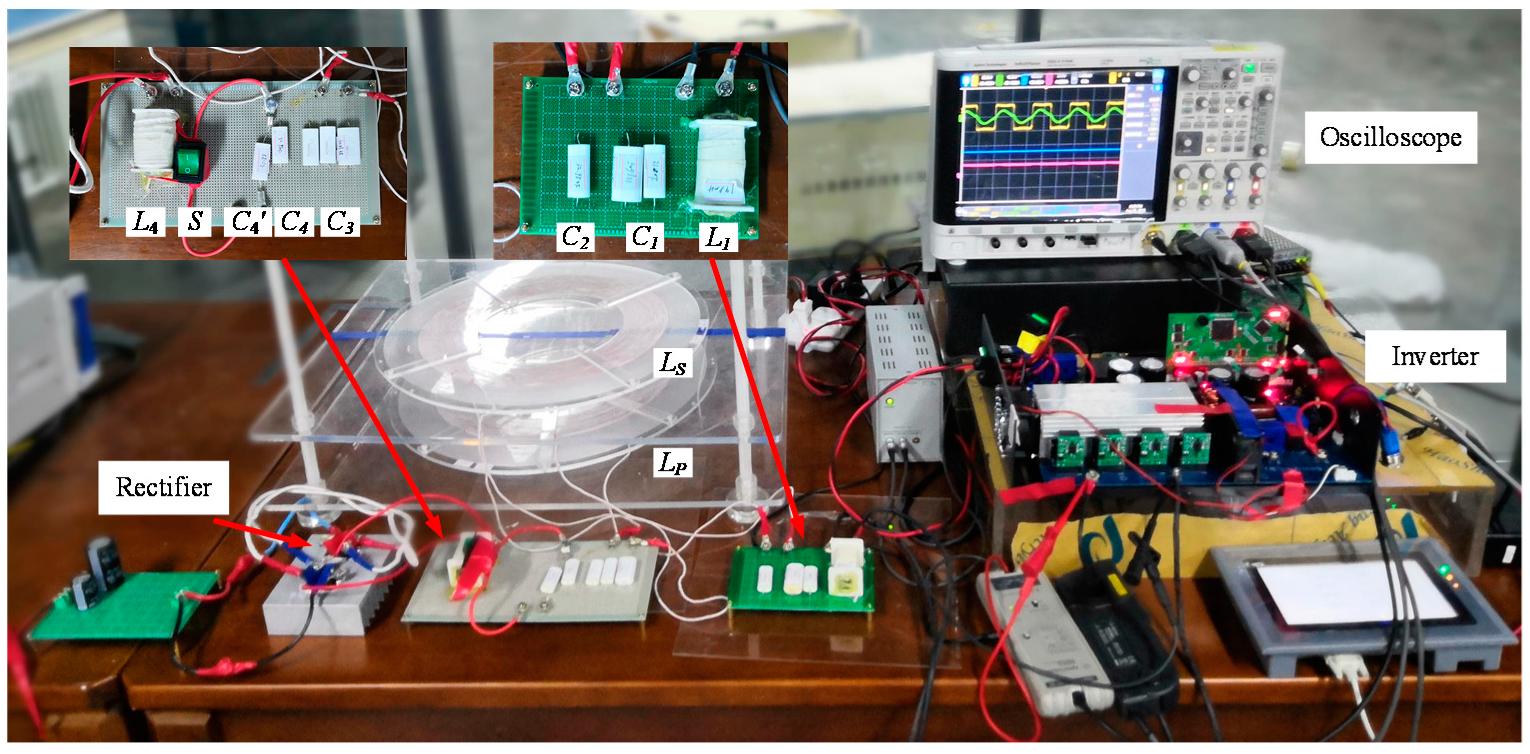
To verify the analysis above, an experimental prototype shown in Figure 12 was built. The value of L4 can be directly calculated by battery parameters and is independent of other parameters through the first method, as shown in Figure 10. So, the experimental platform is set up according to Figure 11. The parameters of the compensation networks are provided in Table 2. The dc input voltage Ud is 40 V. The primary and secondary coils are both round structures, the diameters are 75 mm and 35 mm, respectively. The air gap is set to 8 mm. Switches S1,2,3,4 of full bridge inverter are IPW90R120C3 and secondary rectifier diodes are DSEI2 × 101. The output filter uses Cf of 560 µF. The internal resistance of battery can be equivalent to the non-linear resistance [15,16]. In this experiment, an electronic load with wide range was used to simulate the equivalent behavior of batteries during charging. For simplicity, the whole charging profile is set to two sections: charging current IB 1A and charging voltage UB 64 V.
Firstly, the results of CC mode were analyzed. With different load resistance, the output waveforms uin, iin of the inverter, and the current iP are shown in Figure 13. The transient waveforms uB and iB with load resistance switching from 40 Ω to 60 Ω are shown in Figure 14. It can be seen that under the symmetrical T-type compensation parameters, the waveform of iin is always nearly in phase with uin. Nearly zero reactive power is generated in this case of well compensation. The current flowing through the transmitting coil is independent of the load. In Figure 14, the charging current IB of IPT is 1.0 A at RB = 40 Ω and 994 mA at 60 Ω. The fluctuation margin of charging current is less than 1% and the charging process is basically constant. After the circuit is stabilized, the load voltage increases with the increase of the load.
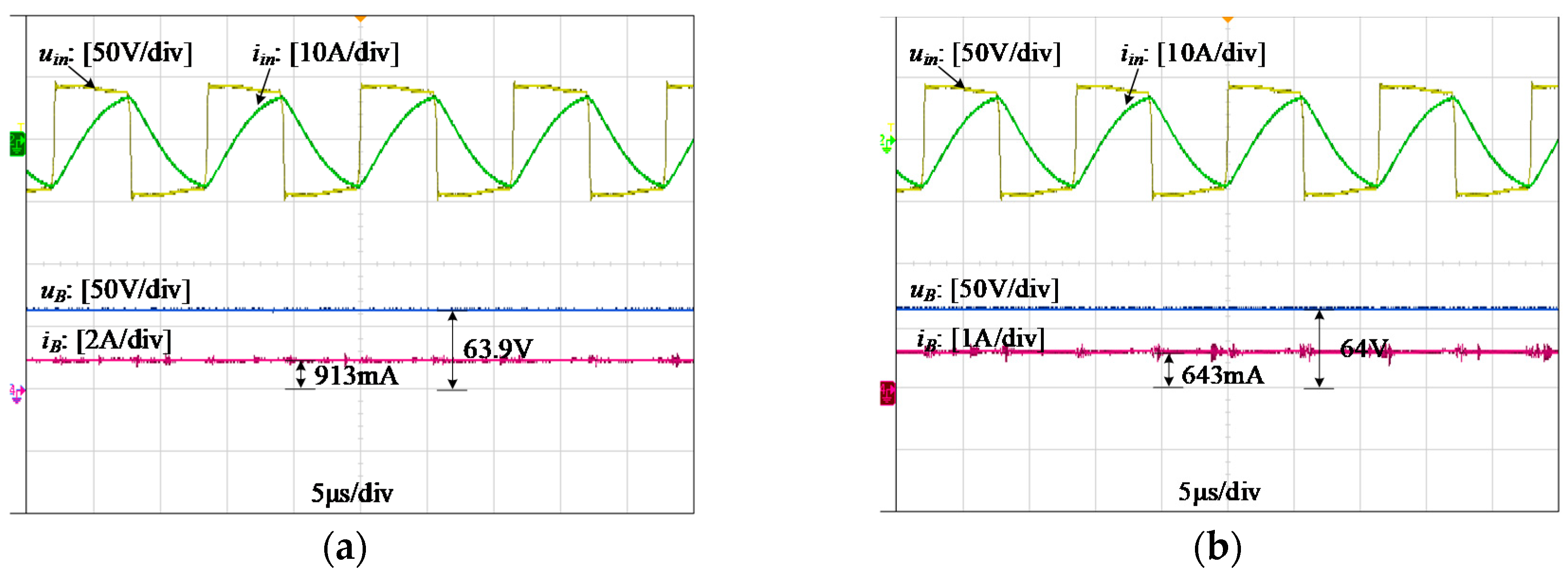
The results of CV mode are shown in Figure 15 and Figure 16. As shown in Figure 11, the IPT system operates in CV mode when switch S is ON, in which the capacitor changes from C4 to C4_CV by paralleled connection of C4′ to C4. The value of equivalent capacitor is given as
C 4 _ C V = C 4 + C 4
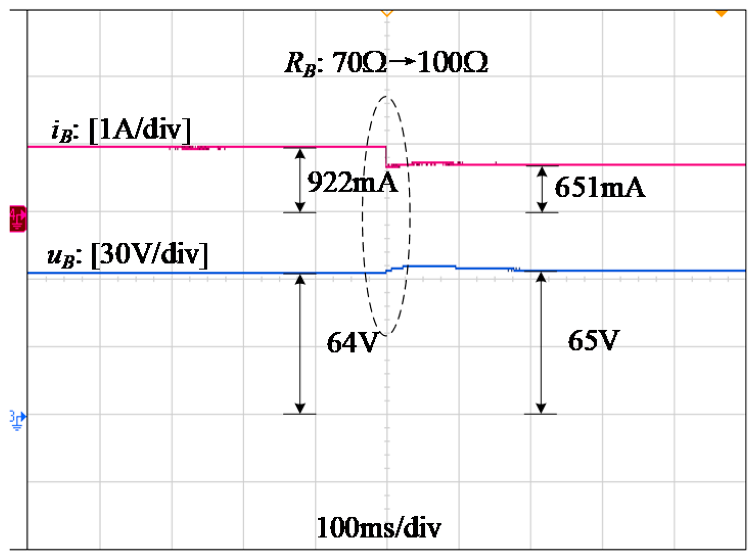
The capacitance C4 changes from 33 uH to 66 uH. Figure 15 shows the output waveforms uin, iin of the inverter, and the output waveforms uB, iB of load under different resistance. The waveform of iin lags behind uin, which illustrates that IPT is charging with reactive power at CV mode. In Figure 16, the charging voltage uB of IPT system is 63.9 V at RB = 70 Ω and 64 V at 100 Ω. It remains constant after the circuit is stabilized, and the load current decreases with the increase of the load. The fluctuation margin of charging voltage is less than 1% and the charging process is basically constant.
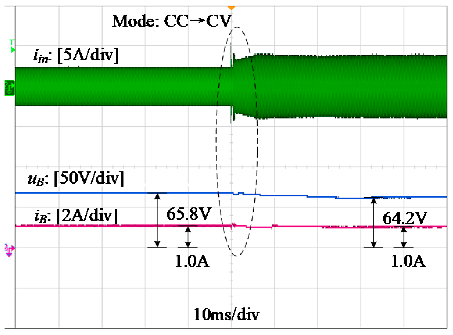
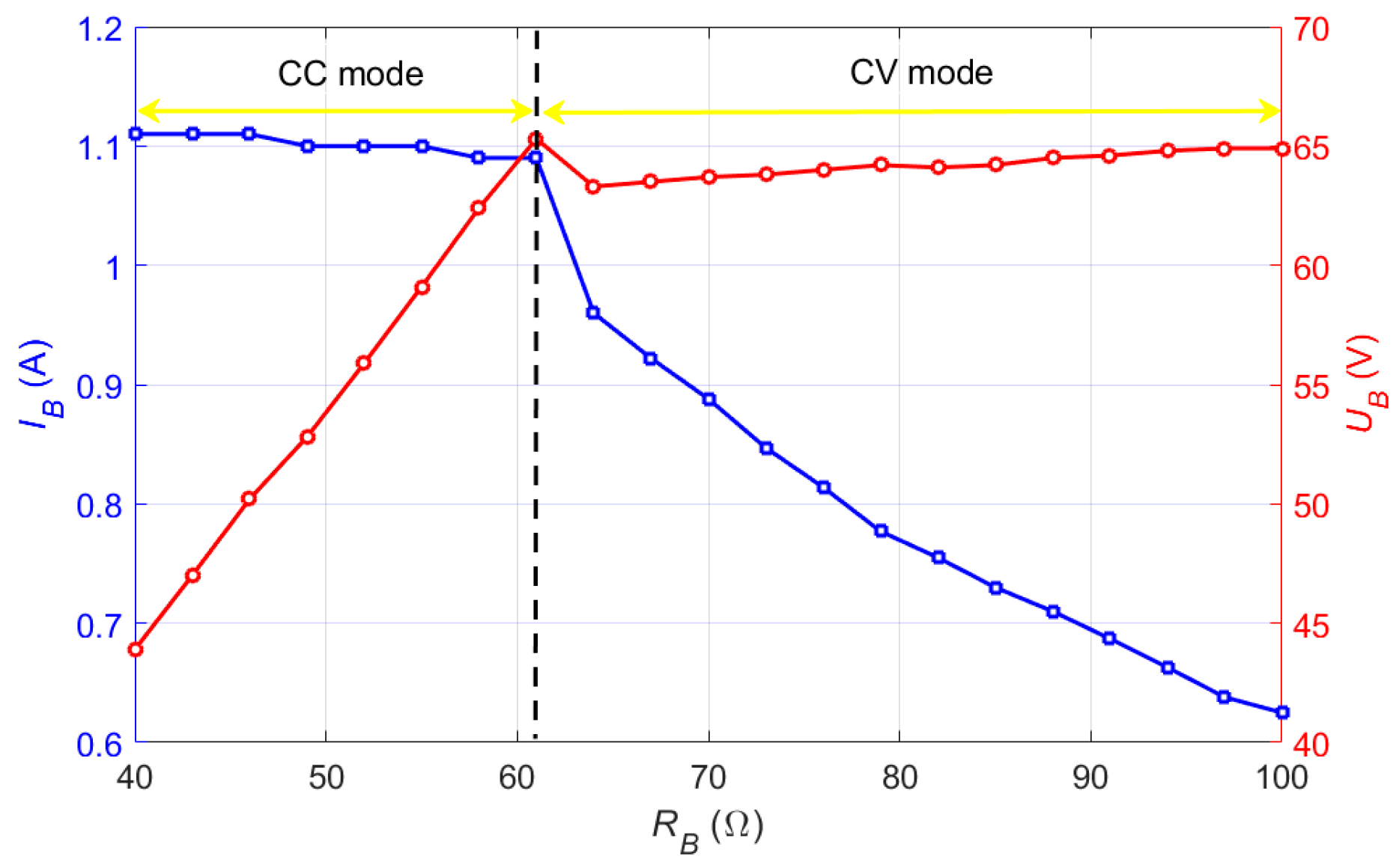
Figure 17 shows the charging mode changing from CC mode to CV mode, while the battery voltage uB and current iB change smoothly during the mode transition. In CC mode, the charging current iB varies from 1.11 A at RB = 40 Ω to 1.09 A at RB = 64 Ω, and the fluctuation margin of iB is 1.8%. The charging voltage uB varies from 63.5 V at RB = 67 Ω to 64.9 V at RB = 100 Ω, and the fluctuation margin of uB is less than 2.5%. The whole charging profile, including charging current IB and charging voltage UB versus RB, is shown in Figure 18. At the beginning of charging, the battery current is maintained at 1 A. With the increase of the equivalent battery load, the battery voltage increases to the required 64 V and then remains stable.

5. Conclusions

In this study, a DLCC compensated IPT system was designed to achieve load independent constant current output and constant voltage output for battery charging applications. The characteristics of LCC compensate network with three design freedoms has been analyzed in detail. According to the theoretical analysis, two parametric design methods of realizing CC mode and CV mode have been proposed. With one switch and an additional capacitor, a smooth mode transition can be achieved. The fluctuation margins of charging current and charging voltage are both less than 2.5%, which meets the charging requirements of batteries. The experimental results agree well with the performance of the proposed method which demonstrates that it is feasible to a given charging characteristics of battery.

Author Contributions

Writing—original draft, J.Y.; formal analysis, X.Y.; investigation, Q.L. and Y.S.; writing—review & editing, X.Z.

Funding

This research was funded by the Fundamental Research Funds for the Central Universities, grant number E19JB500180.

Conflicts of Interest

The authors declare no conflict of interest.

References

  1. RamRakhyani, A.K.; Mirabbasi, S.; Chiao, M. Design and optimization of resonance-based efficient wireless power delivery systems for biomedical implants. IEEE Trans. Biomed. Circuits Syst. 2011, 5, 48–63. [Google Scholar] [CrossRef] [PubMed]
  2. Wu, R.; Li, W.; Luo, H.; Sin, J.K.; Yue, C.P. Design and characterization of wireless power links for brain–machine interface applications. IEEE Trans. Power Electron. 2014, 29, 5462–5471. [Google Scholar] [CrossRef]
  3. Patil, D.; Mcdonough, M.K.; Miller, M.; Fahimi, B.; Balsara, P.T. Wireless Power Transfer for Vehicular Applications: Overview and Challenges. IEEE Trans. Transp. Electrifi. 2018, 4, 3–37. [Google Scholar] [CrossRef]
  4. Li, S.; Mi, C.C. Wireless Power Transfer for Electric Vehicle Applications. IEEE J. Emerg. Sel. Topics Power Electron. 2015, 3, 4–17. [Google Scholar]
  5. Buja, G.; Bertoluzzo, M.; Mude, K.N. Design and Experimentation of WPT Charger for Electric City Car. IEEE Trans. Ind. Electron. 2015, 62, 7436–7447. [Google Scholar] [CrossRef]
  6. Han, W.; Chau, K.T.; Zhang, Z. Flexible induction heating using magnetic resonant coupling. IEEE Trans. Ind. Electron. 2016, 64, 1982–1992. [Google Scholar] [CrossRef]
  7. Han, H.; Mao, Z.; Zhu, Q.; Su, M.; Hu, A.P. A 3D Wireless Charging Cylinder with Stable Rotating Magnetic Field for Multi-Load Application. IEEE Access. 2019, 7, 35981–35997. [Google Scholar] [CrossRef]
  8. Kang, X.U.; Chen, X.; Liu, D. Electrical Impedance Transformation Techniques for an Ultrasonic Coupling Wireless Power Transfer System under Sea Water. Proc. CSEE 2015, 35, 4461–4467. [Google Scholar]
  9. Qu, X.; Chu, H.; Wong, S.C.; Chi, K.T. An IPT Battery Charger with Near Unity Power Factor and Load-independent Constant Output Combating Design Constraints of Input Voltage and Transformer Parameters. IEEE Trans. Power Electron. 2019, 34, 7719–7727. [Google Scholar] [CrossRef]
  10. Yilmaz, M.; Krein, P.T. Review of Battery Charger Topologies, Charging Power Levels, and Infrastructure for Plug-In Electric and Hybrid Vehicles. IEEE Trans. Power Electron. 2013, 28, 2151–2169. [Google Scholar] [CrossRef]
  11. Khaligh, A.; Li, Z. Battery, Ultracapacitor, Fuel Cell, and Hybrid Energy Storage Systems for Electric, Hybrid Electric, Fuel Cell, and Plug-In Hybrid Electric Vehicles: State of the Art. IEEE Trans. Veh. Technol. 2010, 59, 2806–2814. [Google Scholar] [CrossRef]
  12. Li, T.; Wang, X.; Zheng, S.; Liu, C. An Efficient Topology for Wireless Power Transfer over a Wide Range of Loading Conditions. Energies 2018, 11, 141. [Google Scholar] [CrossRef]
  13. Li, H.; Li, J.; Wang, K.; Chen, W.; Yang, X. A Maximum Efficiency Point Tracking Control Scheme for Wireless Power Transfer Systems Using Magnetic Resonant Coupling. IEEE Trans. Power Electron. 2015, 30, 3998–4008. [Google Scholar] [CrossRef]
  14. Wu, H.H.; Gilchrist, A.; Sealy, K.D.; Bronson, D. A High Efficiency 5 kW Inductive Charger for EVs Using Dual Side Control. IEEE Trans. Ind. Electron. 2012, 8, 585–595. [Google Scholar] [CrossRef] [Green Version]
  15. Li, Z.; Zhu, C.; Jiang, J.; Song, K. A 3 kW Wireless Power Transfer System for Sightseeing Car Supercapacitor Charge. IEEE Trans. Power Electron. 2017, 32, 3301–3316. [Google Scholar] [CrossRef]
  16. Liu, N.; Habetler, T.G. Design of a Universal Inductive Charger for Multiple Electric Vehicle Models. IEEE Trans. Power Electron. 2015, 30, 6378–6390. [Google Scholar] [CrossRef]
  17. Wang, C.S.; Covic, G.A.; Stielau, O.H. Power Transfer Capability and Bifurcation Phenomena of Loosely Coupled Inductive Power Transfer Systems. IEEE Trans. Ind. Electron. 2004, 51, 148–157. [Google Scholar] [CrossRef]
  18. Auvigne, C.; Germano, P.; Ladas, D.; Perriard, Y. A Dual-topology ICPT Applied to an Electric Vehicle Battery Charger. In Proceedings of the 2012 International Conference on Electrical Machines, Marseille, France, 2–5 September 2012; pp. 2287–2292. [Google Scholar]
  19. Sun, Y.; Zhang, H.; Tao, W.; Ma, J.; Li, L.; Xia, J. Constant-Voltage Inductively Coupled Power Transfer System with Wide Load Range Based on Variable Structure Mode. Autom. Electr. Power Syst. 2016, 40, 109–114. [Google Scholar]
  20. Qu, X.; Han, H.; Wong, S.C.; Tse, C.K.; Chen, W. Hybrid IPT topologies with constant current or constant voltage output for battery charging applications. IEEE Trans. Power Electron. 2015, 30, 6329–6337. [Google Scholar] [CrossRef]
  21. Mai, R.; Chen, Y.; Zhang, Y.; Yang, N.; Cao, G.; He, Z. Optimization of the Passive Components for an S-LCC Topology-Based WPT System for Charging Massive Electric Bicycles. IEEE Trans. Ind. Electron. 2018, 65, 5497–5508. [Google Scholar] [CrossRef]
  22. Ji, L.; Wang, L.; Liao, C.; Li, S. Design of Electric Vehicle Wireless Charging System with Automatic Charging Mode Alteration at Secondary Side. Autom. Electr. Power Syst. 2017, 23, 143–148. [Google Scholar]
  23. Liu, G.; Bai, J.; Cui, Y.; Li, Z.; Yue, C. Double-Sided LCL Compensation Alteration Based on MCR-WPT Charging System. Trans. China Electrotech. Soc. 2019, 34, 1569–1579. [Google Scholar]
  24. Qu, X.; Jing, Y.; Han, H.; Wang, S.; Tes, C.K. Higher Order Compensation for Inductive-Power-Transfer Converters with Constant-Voltage or Constant-Current Output Combating Transformer Parameter Constraints. IEEE Trans. Power Electron. 2017, 32, 394–405. [Google Scholar] [CrossRef]
  25. Li, S.; Li, W.; Deng, J.; Nguyen, T.D.; Mi, C. A double-sided LCC compensation network and its tuning method for wireless power transfer. IEEE Trans. Veh. Technol. 2015, 64, 2261–2273. [Google Scholar] [CrossRef]
  26. Kan, T.; Nguyen, T.D.; White, J.C.; Malhan, R.K.; Mi, C. A New Integration Method for an Electric Vehicle Wireless Charging System Using LCC Compensation Topology: Analysis and Design. IEEE Trans. Power Electron. 2017, 32, 1638–1650. [Google Scholar] [CrossRef]
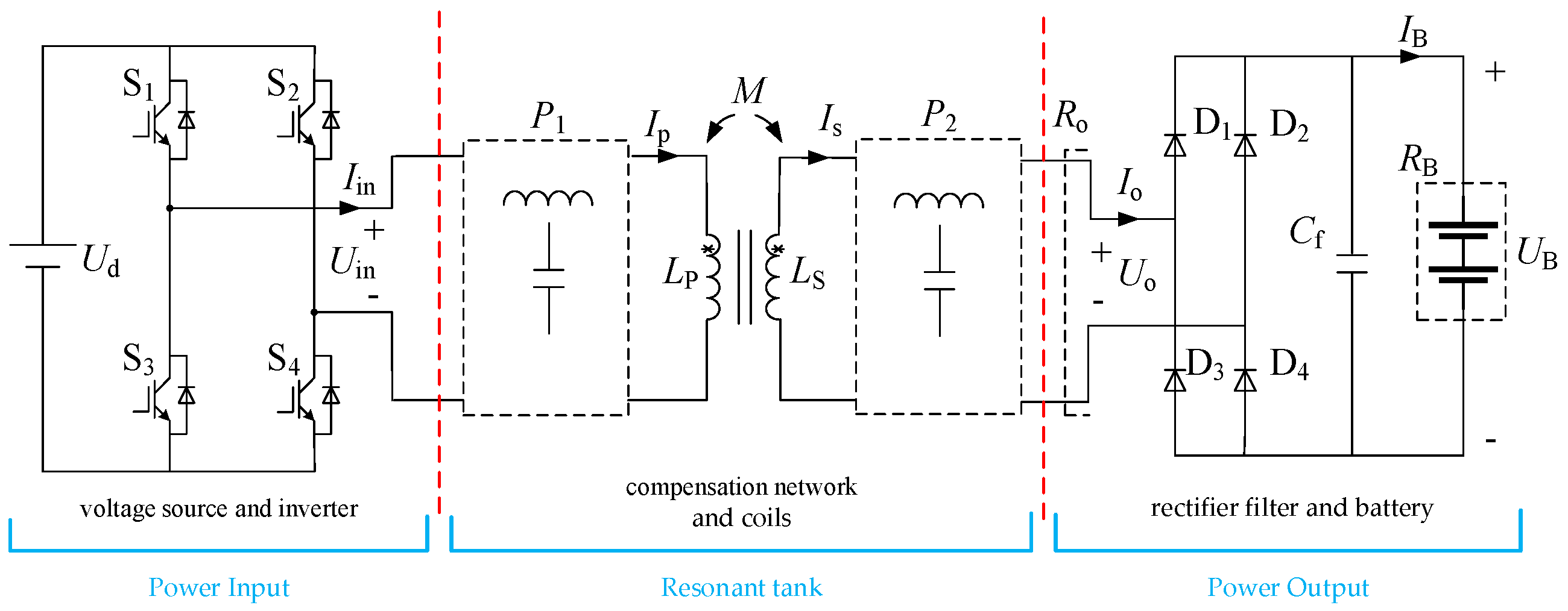
Figure 1. Wireless battery charging system.
Energies 12 03818 g001
Figure 2. Circuit of DLCC compensation topology.
Energies 12 03818 g002
Figure 3. Relationship between IO, UO and f. (a) λ3 = λ2 = 1-λ1 = 0.72; (b) λ3 = λ2 = 1-λ1 = 0.28.
Energies 12 03818 g003
Figure 4. Relationship between IO and λ1, λ2.
Energies 12 03818 g004
Figure 5. IO versus normalized parameters.
Energies 12 03818 g005
Figure 6. Relationship between of UO and λ1, λ2.
Energies 12 03818 g006
Figure 7. UO versus λ1, λ2 in CV mode.
Energies 12 03818 g007
Figure 8. Phase angle of input impedance in CC mode.
Energies 12 03818 g008
Figure 9. Phase angle of input impedance in CV mode.
Energies 12 03818 g009
Figure 10. Flowchart of parameters design.
Energies 12 03818 g010
Figure 11. Two methods of charging mode conversion.
Energies 12 03818 g011
Figure 12. Prototype of the WPT charging system.
Energies 12 03818 g012
Figure 13. Experimental waveforms of uin, iin, and iP in CC mode when (a) RB = 40 Ω and (b) RB = 60 Ω.
Energies 12 03818 g013
Figure 14. Transient waveforms switch from 40 Ω to 60 Ω at CC mode.
Energies 12 03818 g014
Figure 15. Experimental waveforms of uin, iin in CV mode when (a) RB = 70 Ω and (b) RB = 100 Ω.
Energies 12 03818 g015
Figure 16. Transient waveforms from 70 Ω switch to 100 Ω at CV mode.
Energies 12 03818 g016
Figure 17. Transient waveforms of iin, uB and iB from CC mode to CV mode.
Energies 12 03818 g017
Figure 18. Measured charging profile versus RB.
Energies 12 03818 g018
Table 1. System specification and parameter values.
SymbolValueSymbolValue
L119.95 μHLS147.6 μH
LP603.8 μHL4106.24 μH
C1183.02 nFC380.94 nF
C25.94 nFC433 nF
Ui40 VRO40–100 Ω
M34.21 μHf85 kHz
Table 2. Theoretically calculated parameter values of first method.
λ1λ2 for CC Modeλ2 for CV Modeλ3
0.280.720.360.72
C3C4C4L4
80.94 nF33 nF66 nF106.24 μH
Table 3. Theoretically calculated parameter values of second method.
λ1 for CC Modeλ1 for CV Modeλ2λ3
0.720.440.280.56
C3C3C4L4
33 nF51.51 nF80.94 nF82.63 μH