Abstract
An experimental investigation has been carried out to compare the performance and emissions of a low-compression-ratio Euro 5 diesel engine featuring high EGR rates, equipped with different injector technologies, i.e., solenoid, indirect-acting, and direct-acting piezoelectric. The comparisons, performed with reference to a state-of-the-art double fuel injection calibration, i.e., pilot-Main (pM), are presented in terms of engine-out exhaust emissions, combustion noise (CN), and fuel consumption, at low–medium engine speeds and loads. The differences in engine performance and emissions of the solenoidal, indirect-acting, and direct-acting piezoelectric injector setups have been found on the basis of experimental results to mainly depend on the specific features of their hydraulic circuits rather than on the considered injector driving system.
1. Introduction
In the last few years, significant improvements have been made, by the automotive industry, in the development of innovative solutions that are able to comply with increasingly stringent international regulations, in terms of reduction of both CO2 and pollutant emissions [1]. One of the main research fields in the diesel sector deals with the development of the Common Rail (CR) fuel injection systems [2,3,4] and the related fuel injection strategies [5].
Fuel spray formation plays a fundamental role in diesel engines, as the interaction between the injected fuel and the in-cylinder intake charge affects pollutant formation to a great extent [6]. For instance, a greater air entrainment in the spray can lead to a reduction in soot emissions, but can also increase NOx as combustion temperatures increase [7]. In this regard, a major role is played by diesel injectors, which are one of the core components of CR systems [8,9]. Two main driving technologies exist to control the needle lift, and diesel injectors can thus be classified into solenoid- [10,11] or piezoelectric-driven [12,13]. In this latter category, it is possible to further distinguish between direct- and indirect-acting piezo injectors.
Solenoid injectors obtain the needle upstroke thanks to a magnetic field that is generated by means of an electric current circulating in a coil, while the piezoelectric ones use piezoelectric crystals that are able to elongate when subjected to an electric potential difference [14]. The solenoid technology has proved to be robust and simple, and it is the most widely adopted in diesel automotive engines. Nevertheless, it is often claimed that the piezoelectric alternatives have a wider range of potentialities than their conventional solenoid counterparts [15]. Ueda et al. [16], applying the same fuel injection calibration (featuring a double pilot injection), stated that a 4th generation indirect-acting piezoelectric injector could achieve lower soot emissions, thanks to its steeper fuel injection rate than a 4th generation solenoid reference measurement. Moreover, a potential fuel consumption reduction of up to 2.8% was also pointed out, thanks to the fast opening and closing of the needle which creates a short injection and combustion duration. Kim et al. [17] compared direct- and indirect-acting piezo injector performance, and pointed out that direct-acting piezo injectors could reduce NOx emissions, with only slight HC penalties, in most of the analyzed tested conditions. In fact, most of the conditions considered in their study resulted in a higher heat release rate in the premixed combustion phase when an indirect piezo injector was used.
The fuel spray pattern and atomization characteristics of indirect-acting piezo injection systems may be different from those of the solenoid-driven technology, and may be a potential source of improvement for fuel consumption and reduction of exhaust pollutant emissions from the engine [18]. In this regard, not only can the particular driving technology (piezo or solenoid) play an important role, but also the hydraulic layout and the mechanical setup of each injector [19]. If a solenoid-driven injector features an innovative pressure-balanced pilot-valve layout, its static leakage can be reduced significantly, by up to 25% less than similar injectors featuring standard pilot valves [20,21]. Moreover, a further reduction, of up to 50%, may be obtained if the innovative pressure-balanced pilot-valve is coupled with an integrated Minirail [22]. The hydraulic setups commonly applied to modern indirect-acting piezo injectors may be endowed with 3-way pilot valves [23] and bypass-circuits [19], with both devices affecting the dynamics of the injector control chamber, which is placed at the rear of the needle. The 3-way pilot-valve has the potential to reduce the dynamic leakage of the injector, while the bypass-circuit can improve the dynamic response of the needle during the nozzle closure phase [23].
When the direct-acting piezoelectric technology is implemented, the injector needle is directly actuated by the piezoelectric driving system, without the need for any pilot-valve: in this way, a reduction of the injector leakage, major control of the injected quantity, flexible multiple injections and flowrate shaping capabilities are all claimed benefits of this solution [24].
The present work has the aim of comparing the performance of solenoid-driven, direct, and indirect piezo-driven injectors in terms of engine-out pollutant emissions, fuel consumption and combustion noise (CN), under different working conditions in a low-compression-ratio diesel engine for passenger cars. The considered solenoid-driven injector is equipped with a pressure-balanced pilot-valve and an integrated Minirail, while the indirect-acting piezo-driven injector is endowed with a bypass-circuit and the direct-acting one features a feedback control strategy of the injected fuel mass.
2. Experimental Setup and Engine Conditions
The experimental tests were performed on a 2.0 L, four-cylinder, four-stroke diesel engine, fueled with conventional diesel oil (EN 590), whose main technical specifications are reported in Table 1.

Table 1.
Main technical specifications of the engine adopted for the experimental tests.
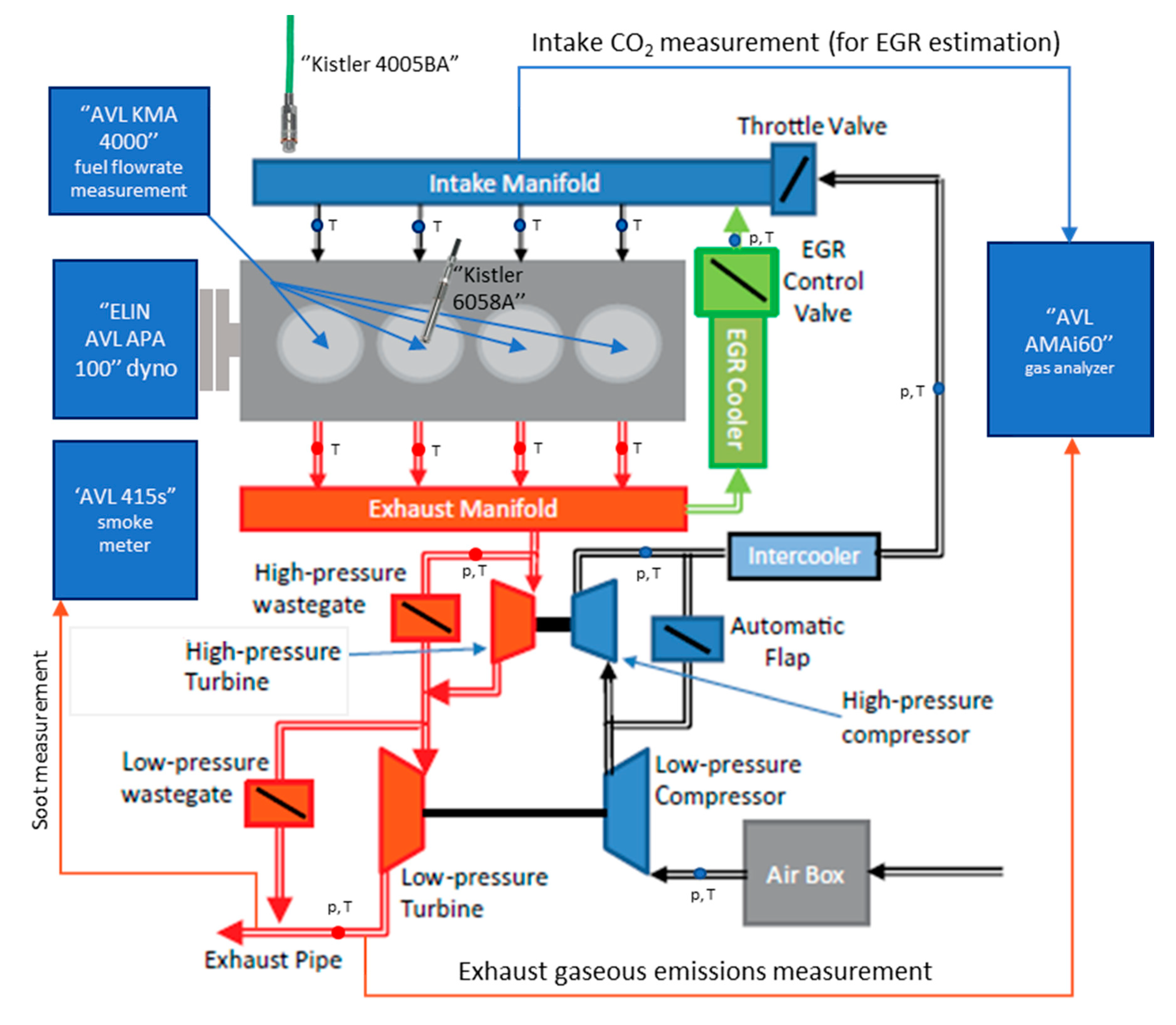
A simplified scheme of the engine is shown in Figure 1. It is homologated for Euro 5 regulations and equipped with a high-pressure CR fuel injection system, a twin-stage turbocharger regulated by means of valve actuators and wastegate valves and a short-route high-pressure EGR system endowed with an EGR cooler. The EGR valve is installed downstream of the EGR cooler.
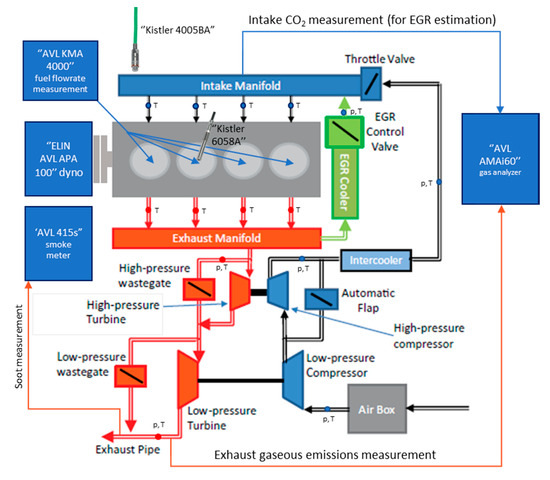
Figure 1.
Scheme of the tested engine installed on the dynamic test bench at the Politecnico di Torino.
The experimental tests were carried out at the dynamic test cell of the Politecnico di Torino (ICEAL—Internal Combustion Engines Advanced Laboratories). This test cell is equipped with an “ELIN AVL APA 100” AC dynamometer and an “AVL KMA 4000” fuel flowrate measuring system. The brake specific fuel consumption (bsfc) values reported in the “Results and discussion” Section were calculated as the ratio of this fuel flowrate measurement to the brake power of the engine.
An “AVL AMAi60” was used to measure the raw gaseous emissions from the engine. It includes a complete analyzer train endowed with devices capable of simultaneously measuring gaseous concentrations of NO, NOx, HC, CH4, CO, CO2, and O2 chemical species, while another analyzer train is only equipped with a CO2 measurement instrument, which was mounted at the intake manifold to estimate the EGR rate to the engine, defined as the ratio of the recirculated exhaust gas mass flowrate to the total mass flowrate inducted in the cylinders [25]:
where and represent the EGR and fresh air mass flowrates, respectively. In the present investigation the calculation of XEGR was performed considering the accurate expression developed in [26], which requires the evaluation of the volumetric concentrations of all the species at the exhaust and the knowledge of the combustion air composition at the inlet. An “AVL 415S” smokemeter was used to measure the soot engine-out emissions.
The test engine was instrumented with a high-frequency piezoelectric pressure transducer (Kistler 6058 A), which was installed on the cylinder head to provide measurements of the gas in-cylinder pressure temporal traces in cylinder #2. A high-frequency piezoresistive pressure transducer (Kistler 4005 BA) was installed in the corresponding intake runner of the same cylinder to obtain the absolute in-cylinder pressure measurement, which was used as a reference. Furthermore, slow-frequency piezoresistive pressure transducers and thermocouples were installed at different positions of the gas flow path (e.g., upstream and downstream of the turbocompressor, intercooler and turbine, in the intake manifold, in the cylinder runners and along the EGR circuit) to perform pressure and temperature measurements (cf. Figure 1).
Finally, all the above-mentioned measurement devices are controlled by AVL Puma Open 1.3.2 and IndiCom automation software. Data post-elaboration was performed with AVL CONCERTO 5 software. AVL CONCERTO 5 was in particular used to calculate the reported CN values, based on the measured in-cylinder pressure signals, which were filtered by means of a low-pass filter with a cut-off frequency of 5 kHz. Each in-cylinder pressure acquisition was averaged over 100 consecutive engine cycles.
Table 2 and Table 3 report the available data to establish the accuracy of the measured pollutant emission values. Previous works [27] have shown that the expanded uncertainties of pollutant emission measurements taken at this engine test facility fall within a 2–4% range. As far as the extended uncertainties pertaining to the brake specific emissions are concerned, the fuel flowrate system accuracy (0.1% over a 0.28–110 kg/h fuel flowrate measurement range) and the maximum errors of the engine speed (1.50 rpm at full scale) and torque (0.30 Nm at full scale) also have to be taken into account.

Table 2.
Composition of the gas calibration cylinder and extended uncertainty (95% confidence interval).

Table 3.
Manufacturer’s data for the measurement errors of the CLD, NDIR, and HFID analyzers.
3. Injector Hydraulic Performance
The three considered injector types, that is a new-generation indirect-acting solenoid (for brevity here referred to as IAS), an indirect-acting piezoelectric (IAP) and a direct-acting piezoelectric (DAP) injector, all feature the same nozzle, conical angle, and geometrical sizes of the needle. However, the IAP and IAS injectors both have a ballistic needle (i.e., it does not reach its stroke end position for all the engine working conditions) with the same key features, while the DAP injector needle is not ballistic and reaches the stroke end at 0.1 mm [12]. Consequently, the capability of the injected fuel flowrate of the DAP injector differs from the other two solutions. In general, the injected mass results to be lower for medium to high ET and prail values, while it leads to a larger injected fuel mass for low ET and prail values, than for IAS and IAP types [22,23]. In the former case, this is due to the reduced needle lift of the DAP injector, which yields a smaller flow restriction in correspondence to the needle-seat passage. In the latter case, the DAP injector delivers more fuel than the other two solutions, because the elongation of its piezoelectric crystal is linked directly to the mechanical actuation of the needle, which is thus able to open more quickly than in the case of an indirect actuation for both IAP and IAS [22,23]. In fact, it has been verified that the injected fuel flowrate of the DAP injector increases with the highest time derivative, at least for lower prail levels than 1200 bar [23].
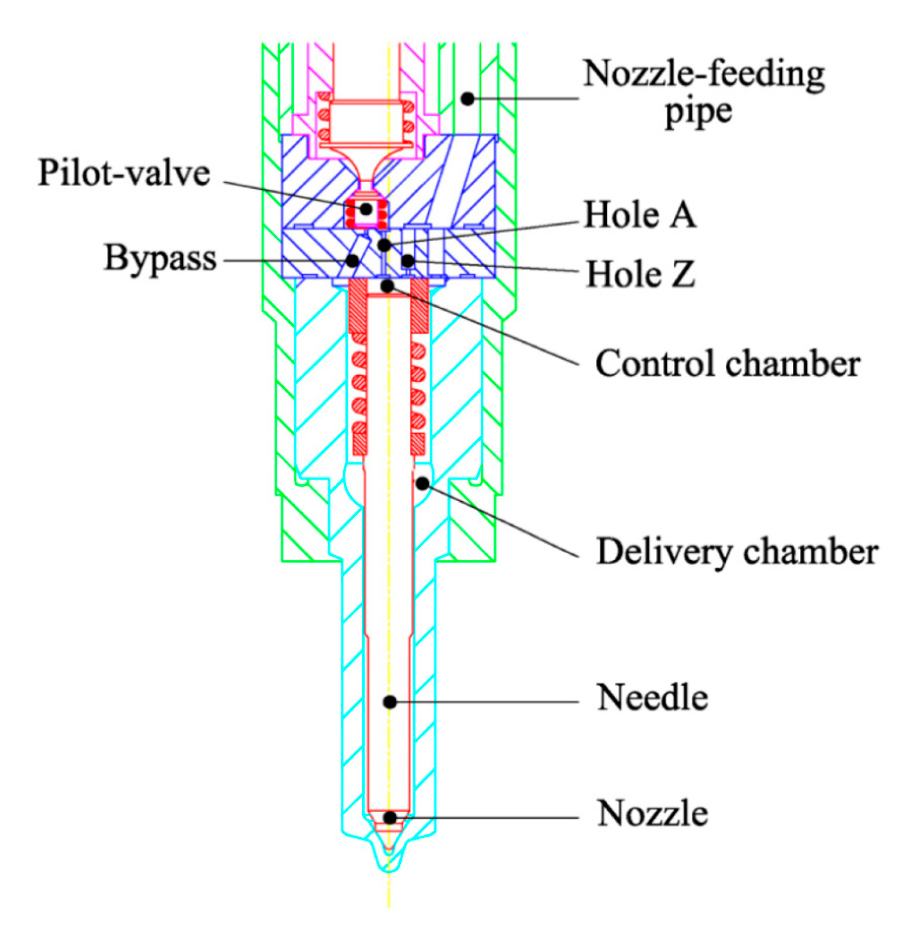
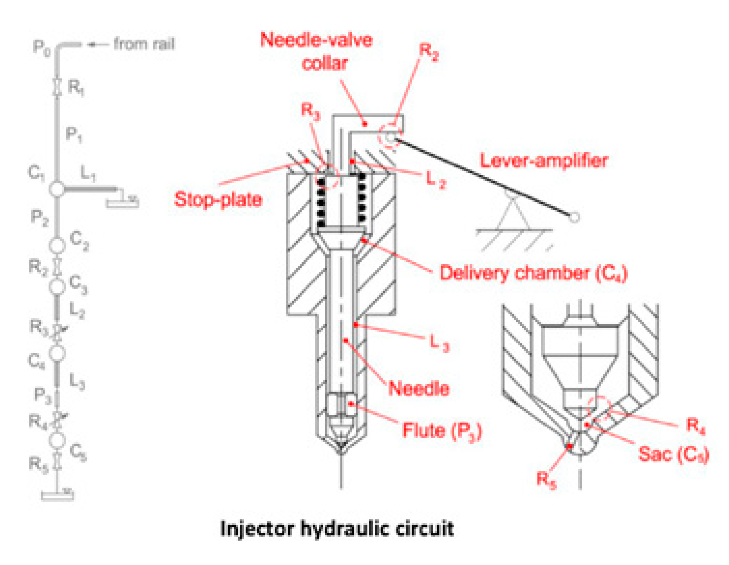
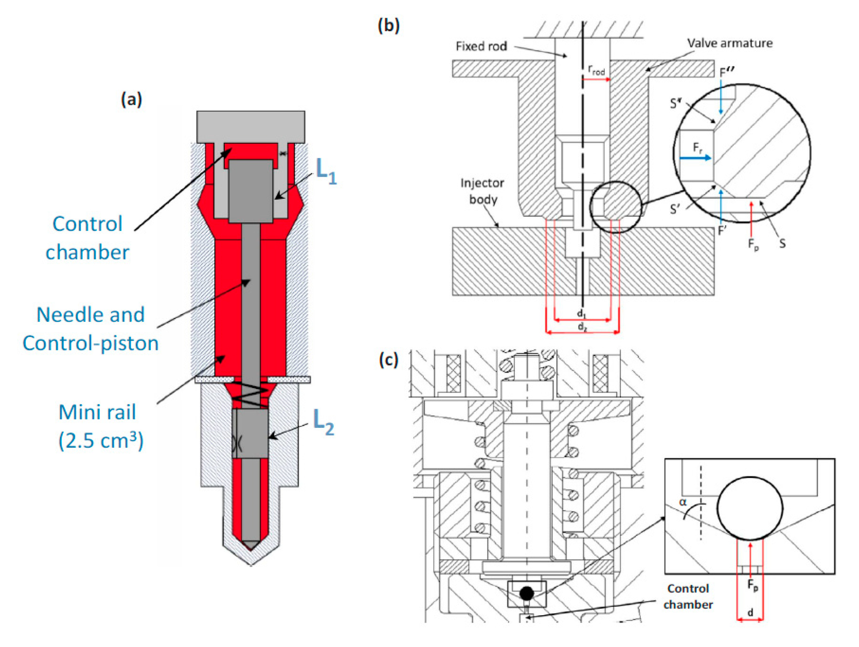
Figure 2 shows a schematic of the indirect-acting piezo-driven injector, endowed with the bypass-circuit [23], while Figure 3 and Figure 4 represent the direct-acting piezo injector [12] and the solenoid-driven one, respectively; the latter highlights the pressure-balanced pilot-valve [22] and a standard pilot-valve.
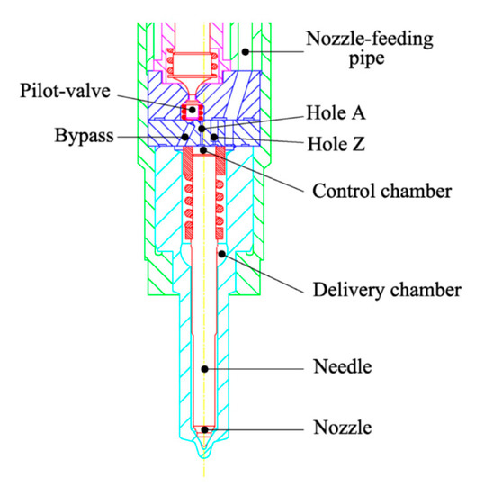
Figure 2.
Schematic of the indirect-acting piezoelectric injector.
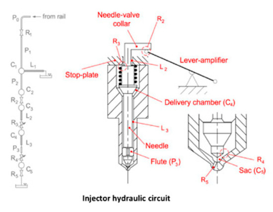
Figure 3.
Schematic of the direct-acting piezoelectric injector.
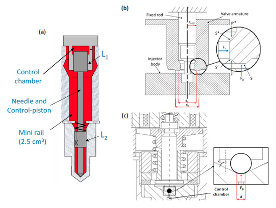
Figure 4.
Solenoid injector. (a) Hydraulic circuit of the injector; (b) Pressure-balanced pilot-valve; (c) Standard pilot-valve.
4. Results and Discussion
The results pertaining to the experimental tests carried out at the dynamometer test cell are presented in what follows, and the performance of the engine is highlighted (in terms of engine-out pollutant emissions, bsfc and CN) when equipped with IAS, IAP, or DAP injectors. The engine was originally provided by the OEM with a state-of-the-art pilot-main (pM) fuel injection calibration referring to IAP injectors. Experimental tests were then carried out with DAP and IAS injectors instead of IAP ones, keeping the same fuel injection calibration, to perform a comparison and investigate their different performance.
Some engine operating points, which were representative of an application of the tested engine to a vehicle over the New European Driving Cycle (NEDC), were selected for the analysis. The resulting key-points (expressed in terms of speed n [rpm] × bmep [bar]) were in the 1.5 bar ≤ bmep ≤ 12 bar and 1000 rpm ≤ n ≤ 2750 rpm ranges. For conciseness reasons, only three key-points are analyzed hereafter: a low load and speed condition, namely 1500 × 2, (whose results are presented in paragraph 4.1), and two medium–high speed and load points, namely 2000 × 5 and 2500 × 8 (whose results are presented in paragraph 4.2). For each working condition, results are presented for the three different injector technologies along some EGR sweeps, to have a wider comparison than that based on the single baseline points. The aim is to compare the performance of IAP, DAP and IAS injectors when the same fuel injection calibration is implemented and to highlight the impact of the particular injector technology on CN, bsfc, and engine-out pollutant emissions.
4.1. Low Load and Speed (1500 × 2)
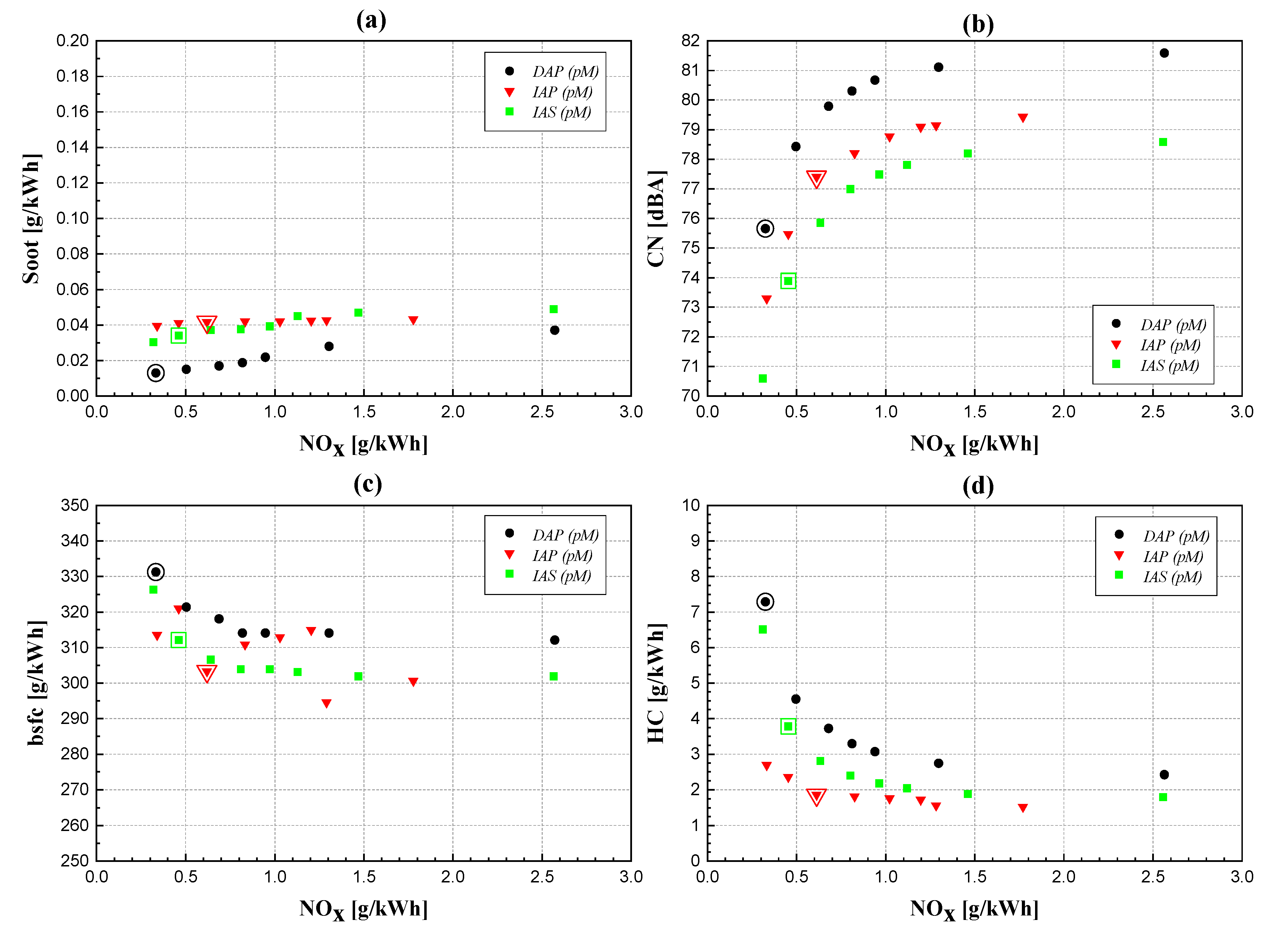
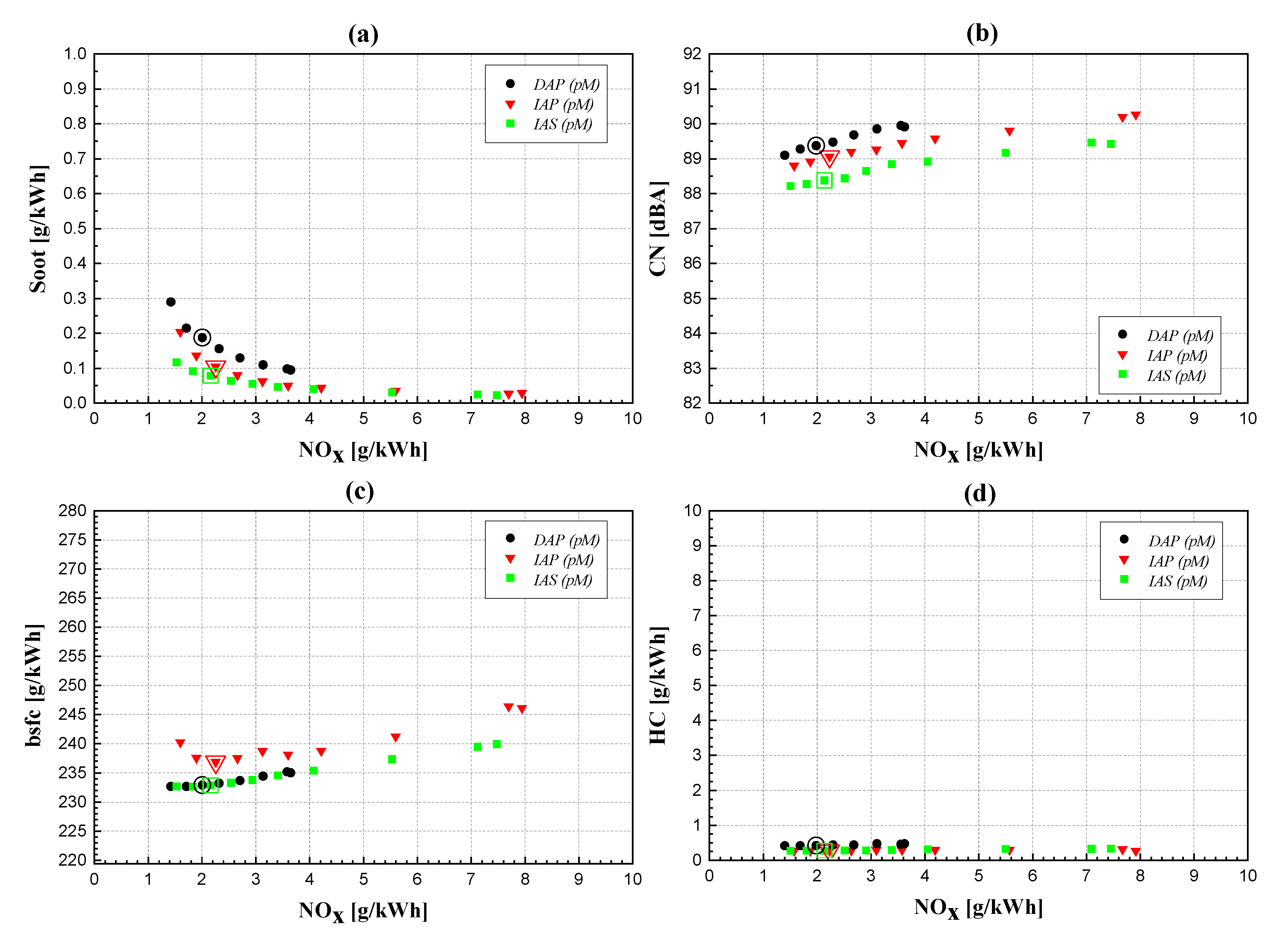
Starting from the baseline double pM calibration (whose main parameters are reported in Table 4) EGR trade-offs were performed at a low speed and load engine point (i.e., 1500 × 2), for the three different injector typologies under investigation. The results of this comparison, in terms of CN, fuel consumption and engine-out pollutant emissions, are shown in Figure 5. Different colors and symbols refer to different injector typologies, while the contoured symbols refer to the baseline calibration results. The x-axis reports the NOx brake specific emissions (in g/kWh) for each diagram, with the lowest values corresponding to the highest applied EGR fractions (XEGR).

Table 4.
Main parameters of the reference pM calibration at 1500 × 2, with IAP injectors. The main quantity is set directly by the test bench to obtain the desired bmep.
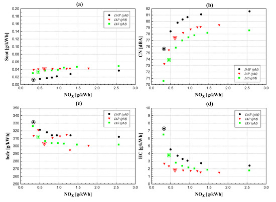
Figure 5.
Engine-out soot emissions (a) CN; (b), bsfc; (c) and engine-out HC emissions; (d) vs. NOx for the three injector typologies, at 1500 × 2.
The engine-out soot and NOx emissions (Figure 5a) do not show the typical trade-off behavior of the conventional diesel combustion mode, for any of the three examined injector configurations. A PCCI-like trend (which means a simultaneous reduction of soot and NOx emissions when XEGR grows) is clearly achieved in each case, thanks to the realization of a high degree of premixed combustion. The high XEGR, in addition to the somewhat delayed fuel injection timings (which make combustion occur mainly during the piston expansion stroke) and the reduced engine compression ratio, are all able to enhance the local mixing of the injected fuel plumes with the inducted charge, producing a highly premixed stratified charge and relatively low peak combustion flame temperatures [28]. Unfortunately, PCCI-like strategies lead to high incomplete combustion species (HC emissions are reported as a reference in Figure 5d, but significant levels were also obtained for CO emissions, which are not presented here for conciseness reasons) and fuel consumption (Figure 5c), which show rapidly worsening trends as the EGR fraction increases. If all the graphs in Figure 5 are compared, the DAP injector provides the worst results, in terms of CN, bsfc, and HC emissions, because it has the highest tendency toward premixed combustion of the three analyzed solutions.
The IAS and DAP injectors are both able to deliver fuel with an improved atomization compared to the IAP solution, especially when relatively low prail and ET values are implemented, as in this case. The improved atomization for the IAS injector can be mainly ascribed to the presence of the integrated Minirail in its hydraulic layout. The Minirail, in fact, is able to maintain a more stable (and thus, higher) injection pressure during both the pilot injection and the first part of the main shot, thereby counterbalancing the pressure reduction due to the injection in the injector delivery chamber, and allowing a faster needle opening [22]. The DAP injector features a faster needle upstroke because of its direct mechanical actuation on the needle, which gives rise to a steeper fuel injected flowrate, at least for prail values below 1200 bar [23]. This improved fuel atomization (with respect to the IAP solution) creates leaner equivalence ratios locally, increases the local oxygen concentration and improves the tendency toward low temperature premixed combustion through an increased autoignition delay and more delayed combustion developments. Unlike high temperature diesel ignition, which mostly arises through the chain-branching H + O2 = O + OH reaction (which means that a decrease in the local oxygen concentration enlarges the autoignition delay and slows down the reaction process), at lower temperatures typical of PCCI-like combustion fuel decomposition and ignition mainly proceed along a different chain-branching reaction (alkyl → alkyl peroxyl → hydroperoxyl alkyl → hydroperoxyl peroxyl → keto-hydroperoxide) [29,30]. In the latter case, unlike the former, the leaner local equivalence ratios (i.e., lower fuel concentrations) achievable with IAS and DAP injectors, thanks to the improved atomization, can reduce the concentrations of fuel radicals inside the air-fuel mixture, thus effectively slowing down the ignition process and increasing the premixed stage of combustion.
As already mentioned, the highest premixed degree is achieved using DAP injectors, thus justifying their worse HC, bsfc, and CN levels in Figure 5. The higher the premixed degree is, the more likely the occurrence of fuel over-mixing and flame quenching phenomena. These phenomena are thought to be the main mechanisms responsible for the emission of incomplete combustion species, i.e., unburned HC and CO, under low speed and low load conditions, together with wall wetting phenomena [31]. Moreover, these phenomena may also negatively affect the fuel economy.
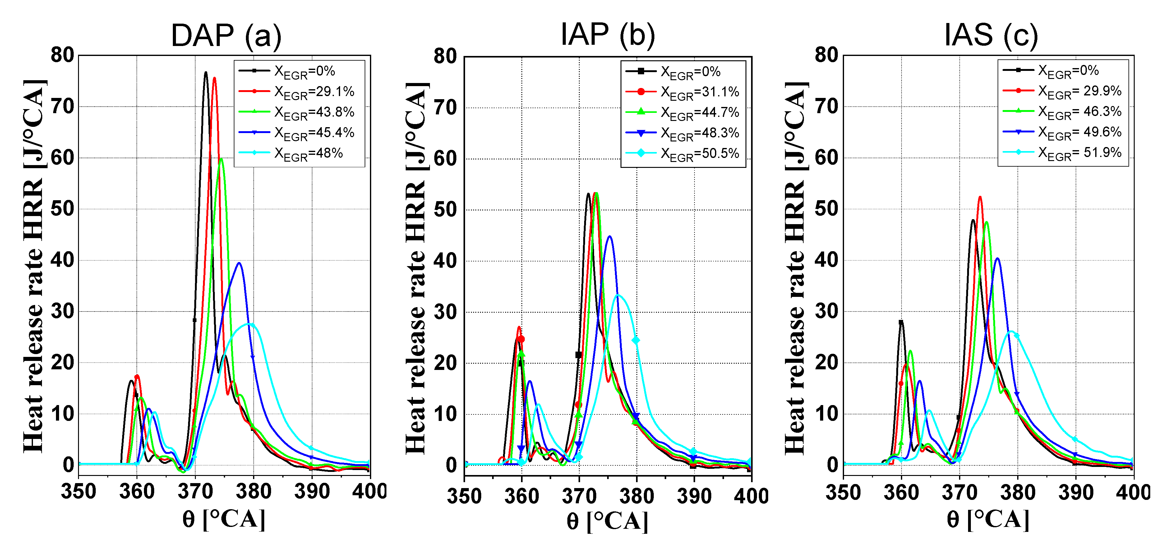
The CN vs. NOx (or the CN vs. EGR rate, as NOx emissions have strong correlations with EGR fractions) trends reported in Figure 5b do not show any trade-off behavior. On the one hand, when the EGR rate increases, the combustion develops more in the premixed stage, primarily thanks to the dilution effect of the recirculated gases, which increase the autoignition delay [25], and this leads to higher HRR peaks, higher cylinder pressure derivatives during the main combustion and deteriorated CN. On the other hand, the reduced combustion velocity, which is induced by a decrease in the oxygen fraction [32], dampens the intensity of the premixed combustion. Furthermore, if the autoignition delay grows, the combustion process tends to develop further during the piston expansion stroke (a late PCCI mode is implemented) and is thus influenced more by the expansion cooling effect, which reduces the cylinder pressure rise. The latter effects tend to prevail over the dilution effect (cf. Figure 6), thus making CN decrease as the EGR rate increases.
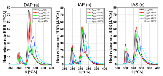
Figure 6.
Comparison of the HRR traces featuring different EGR rates, at 1500 × 2, for the three injector typologies under investigation: (a) DAP; (b) IAP; (c) IAS.
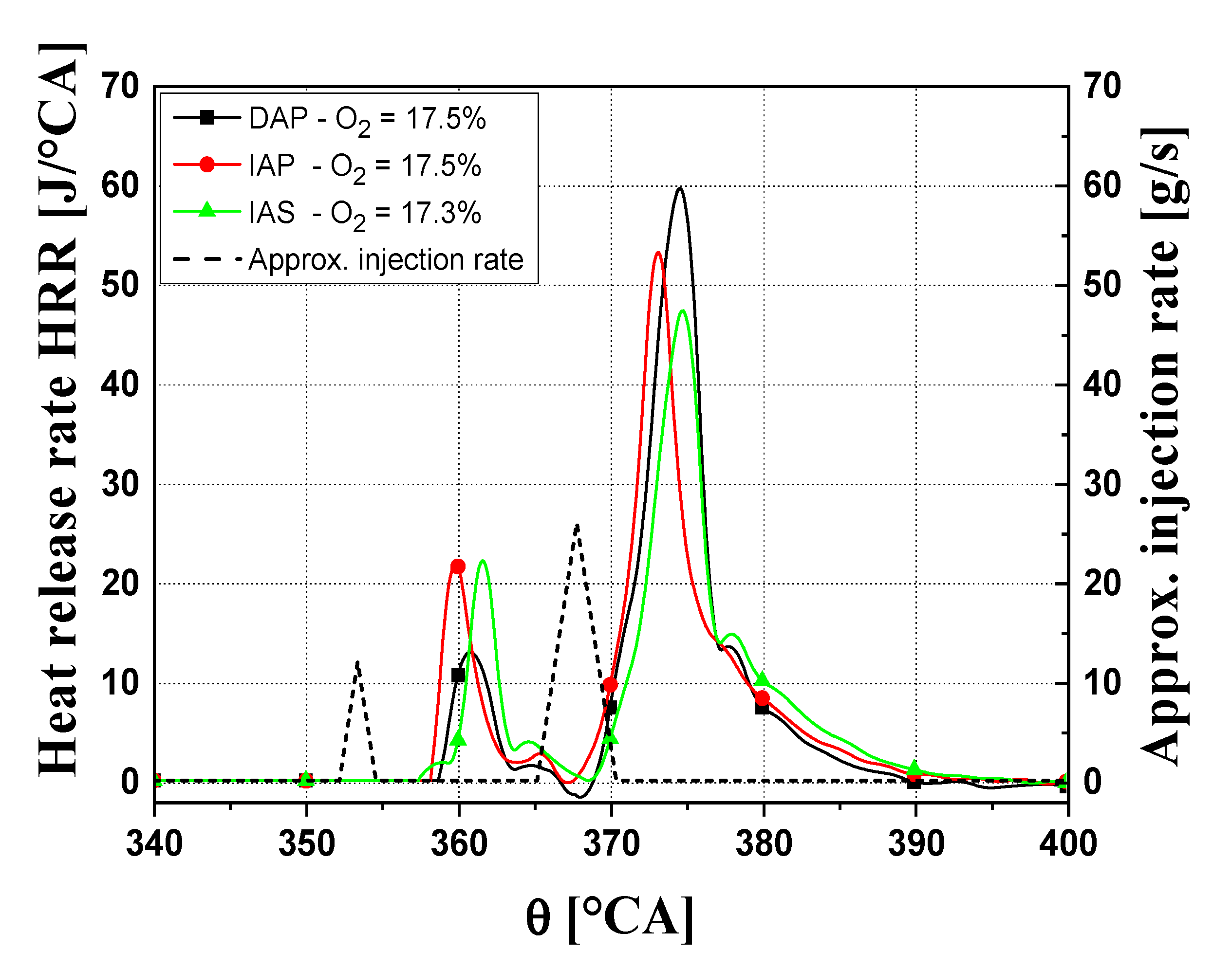
The DAP injector provides a higher CN (and the worst CN-NOx trade-off) than the other two investigated solutions, if a similar EGR rate (i.e., similar intake oxygen concentrations) is applied, while the solenoid injector results to be the best one. Figure 7 shows the HRR traces related to the three injector typologies for almost the same intake oxygen concentration (around 17.5%, corresponding to an XEGR of around 44%). The highest HRR peak pertaining to the DAP injector is likely due to the combination of a longer autoignition delay (as already explained), which increases the premixed stage of combustion, and a larger fuel injected quantity at the start of combustion, thanks to the faster upstroke of its needle than that of the IAP and IAS solutions. The IAS injector features a lower CN level than the IAP one, and its combustion process develops further during the piston expansion stroke with consequent lower HRR peaks. This is mostly due to a better atomization of the IAS injector, which is reached because of the presence of the Minirail [22].
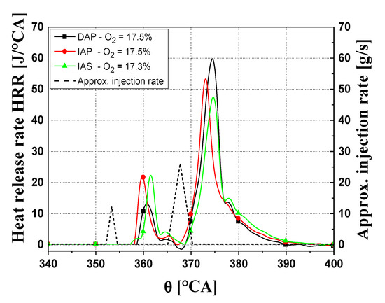
Figure 7.
HRR traces featuring similar EGR rates, at 1500 × 2, for the three injector typologies under investigation.
4.2. Medium–High Speed and Load (2000 × 5, 2500 × 8)
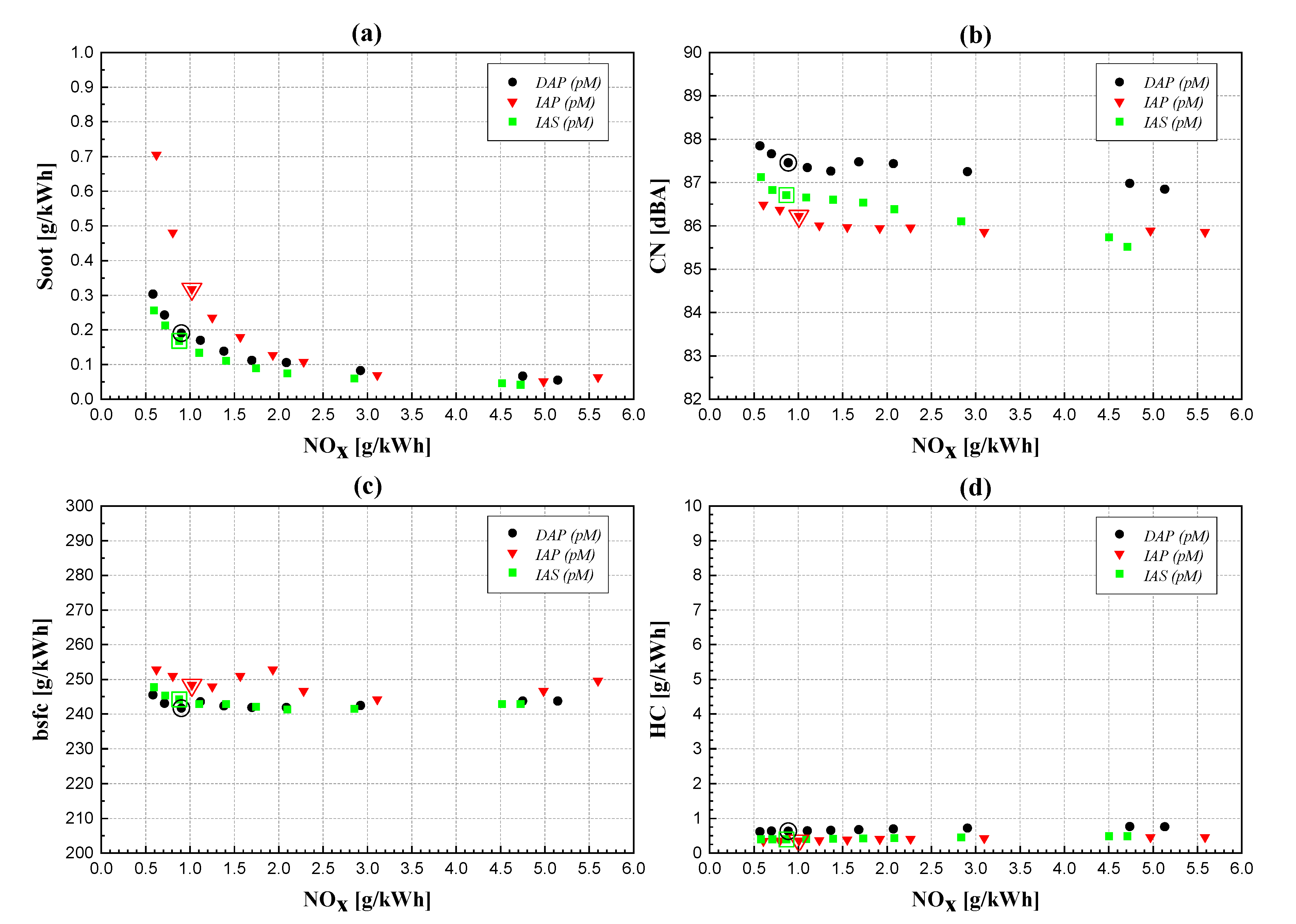
Figure 8 and Figure 9 report the soot, bsfc, CN and HC for the EGR trade-offs performed at two medium speeds and loads (engine points 2000 × 5 and 2500 × 8) for the three different injector types under investigation, in a similar way to the previous section. As has already been seen for the low load and speed engine conditions, the contoured symbols in each graph refer to the baseline tests obtained, for each injector type, when implementing the same baseline double pM calibration (whose main parameters are reported in Table 5) provided by the OEM and originally applied to the engine equipped with the IAP injectors.
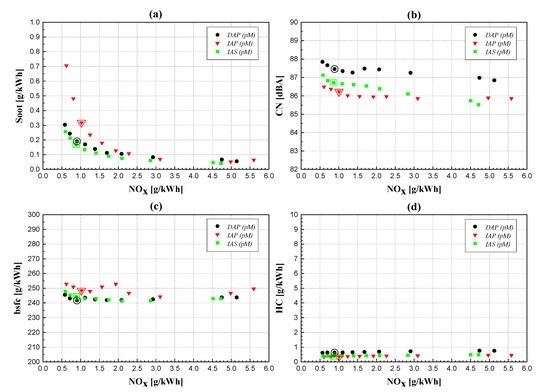
Figure 8.
Engine-out soot emissions (a) CN; (b) bsfc; (c) and engine-out HC emissions; (d) vs. NOx for the three injector typologies, at 2000 × 5.
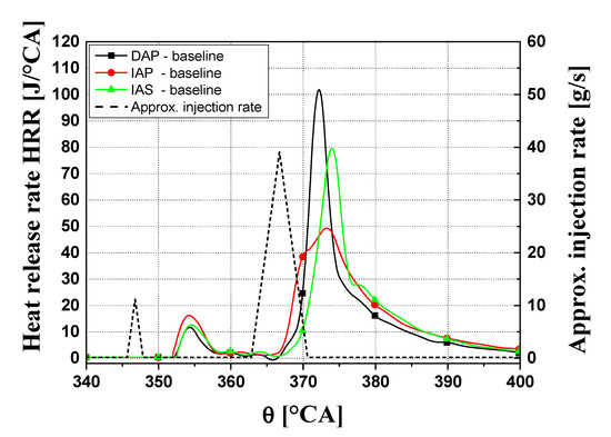
Figure 9.
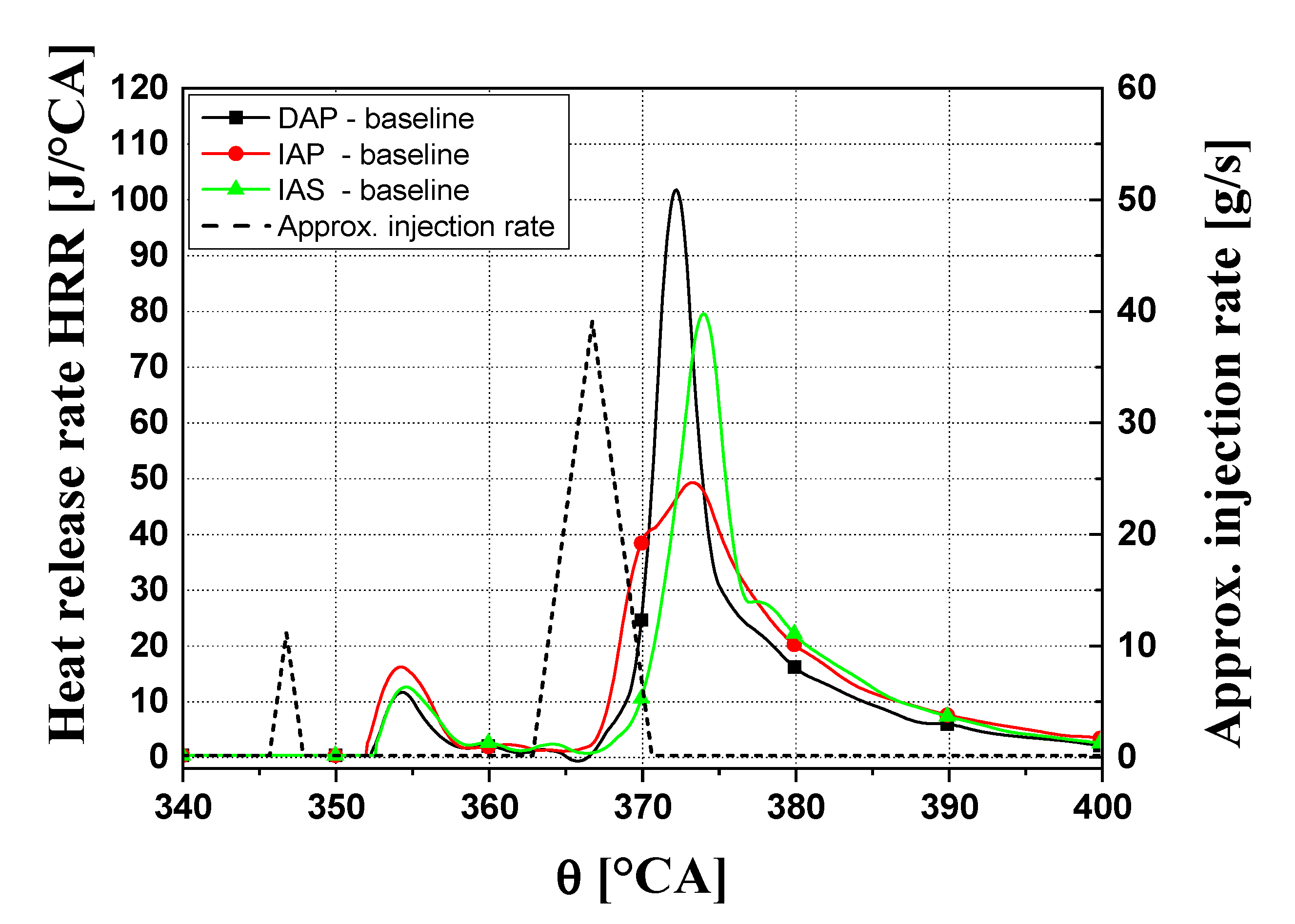
HRR traces of the reference calibrations, at 2000 × 5, for the three injector typologies under investigation.

Table 5.
Main parameters of the reference pM calibration at 2000 × 5 and 2500 × 8, with IAP injectors.
The engine-out soot and NOx emissions at 2000 × 5 (Figure 8a) show a clear trade-off behavior, which is typical of a conventional diesel combustion mode, for each of the three examined injector typologies. Nevertheless, a low-NOx combustion can also be achieved for these higher load and speed conditions, through the application of a relatively delayed fuel injection pattern and a high EGR rate (cf. the contoured symbols in Figure 8, which represent the results pertaining to the reference calibration for each injector type). The worst soot-NOx trade-off can be observed for the IAP injector (cf. triangle symbols in Figure 8a), which features more than doubled soot emissions compared to the other two injector solutions for the highest EGR rates (lowest NOx values). This is because, as already mentioned, the IAP injector gives the worst atomization and the lowest premixed degree, thus entraining the least air inside the injected fuel plumes and locally creating the richest mixture portions, which are prone to forming soot particles.
Differences in fuel consumption (Figure 8c) have been highlighted between the three injectors under investigation. A mean penalty in bsfc of about 3–4% may be observed for the IAP solution, while DAP and IAS show almost the same behavior. However, the differences in fuel leakage between the IAP, DAP and IAS injectors should only play a negligible role at this engine operating point: the IAP and IAS injectors show comparable injector leakages, while the DAP injector, which features the lowest leakage values, does not show any appreciable bsfc reduction. The 3–4% reduction in bsfc, when IAS and DAP injectors are installed, is likely due to the enhancement in the thermal efficiency of the engine deriving from the higher premixed degree, which makes the combustion approach constant volume rather than constant pressure conditions and reduces its overall duration. Unlike the low load case, this gain in thermal efficiency is not offset by any severe CO (here not reported) or HC penalties (Figure 8d). When load increases, concerns about incomplete combustion species are generally mitigated.
The CN vs. NOx trends (cf. Figure 8b) at 2000 × 5 show a slight trade-off behavior, i.e., a slight increase in CN when NOx emissions are reduced as a result of higher EGR rates, unlike what is highlighted at 1500 × 2. In this case, the larger premixed combustion phase prevails over the reduction in combustion velocity due to increased EGR and the damping effect resulting from the delayed combustion that develops along the expansion stroke. This leads to higher HRR peaks, higher cylinder pressure derivatives and increased CN as the EGR fractions grow. The lowest CN level of three injector types is achieved by the IAP injector, with improvement of up to 1–1.5 dBA with respect to the other solutions. The three HRR traces pertaining to the baseline tests, for each injector, are plotted in Figure 9 versus the crankshaft angle. It is clear that the IAP injector determines the lower ignition delay and, thus, less fuel to burn in the premixed stage, and this gives rise to the lowest HRR development and consequently to the lowest CN.
The worst soot-NOx trade-off at 2500 × 8 may be observed for the DAP injector (cf. the circle symbol curve in Figure 10a), while the IAS injector still gives the best results (cf. the square symbol curve), even though the differences between the three solutions are not big. In the case of the IAS injector, the lowest soot production at each EGR level is still due to its higher tendency toward premixed combustion, as a consequence of the presence of the Minirail in the hydraulic layout, which determines a faster needle upstroke and, thus, a better fuel atomization in the first part of the injection. The fact that the DAP injector does not give better results than the IAP, as observed at lower loads, is due to the higher rail pressure (as can be seen in Table 5, the rail pressure at 2500 × 8 is equal to 1200 bar). The needle velocity of the DAP injector for prail ≥ 1200 bar during the upstroke tends to become similar to that of the IAP one, as the increased rail pressure level generates a higher pressure force that counteracts the needle lift.
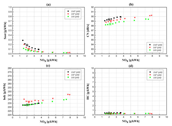
Figure 10.
Engine-out soot emissions (a) CN; (b) bsfc; (c) and engine-out HC emissions; (d) vs. NOx for the three injector typologies, at 2500 × 8.
Once again, the IAP injector shows an increased bsfc (about 3–4% more than the other injector typologies, cf. Figure 10c) compared to the other two injectors. The previously highlighted differences in the premixed combustion portion reflect on the fuel consumptions of the injectors, as occurred at 2000 × 5. Moreover, the considerations on the negligible levels of CO (here not reported) and HC emissions (Figure 10d) for all the considered injector types are even more valid at this higher considered load.
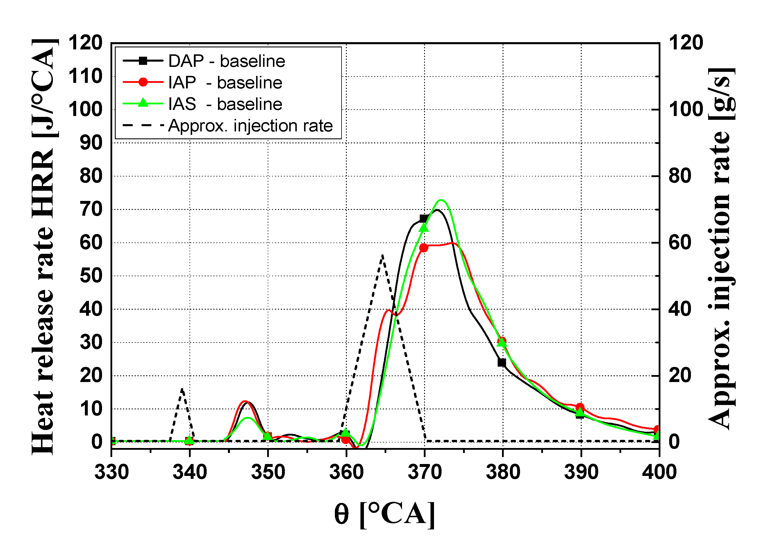
Finally, the CN (Figure 10b) has been confirmed to be higher for the DAP injector, even though it does not highlight the maximum HRR peak (cf. Figure 11) as it does at 2000 × 5. In fact, when double injection is performed, CN not only correlates with the heat release peak of the main injection (HRRpk2), but also with that of the pilot shot (HRRpk1) and with the timings of the two HRR bumps [33]. However, smaller differences are present at 2500 × 8 for the three injectors, than for the previously analyzed points.
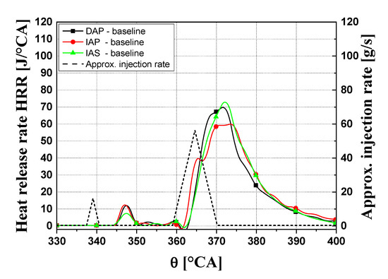
Figure 11.
HRR traces of the reference calibrations, at 2500 × 8, for the three injector typologies under investigation.
Figure 11 reports the three HRR traces versus the crankshaft angle pertaining to the baseline tests at 2500 × 8 for all the injector types. Again, in this case, the IAP injector determines the lowest autoignition delay, even though the differences are smaller than in the previous cases.
5. Conclusions
The experimental investigation has concerned a comparison of the performance of indirect-acting solenoid-driven, direct, and indirect piezo-driven injectors in terms of engine-out pollutant emissions, bsfc and CN, under different working conditions in a low temperature combustion diesel engine for passenger cars (a pilot-Main pM fuel injection strategy was adopted in all of the tested calibrations).
It is possible to avoid the typical NOx-soot trade-off of a conventional diesel combustion mode at low loads and speeds, i.e., at 1500 × 2, and thus to simultaneously obtain low-NOx and low-soot PCCI-combustion for all of the three investigated injector types, even though the PCCI behavior is more pronounced for the DAP injector. In fact, the DAP injector provides penalties of about 2–3 dBA, in terms of CN, and the worst bsfc and HC trade-offs. In general, both the IAS injector (due to the presence of the Minirail integrated in its hydraulic layout) and DAP injector (due to its direct mechanical actuation on the needle) are able to deliver the fuel with an improved atomization compared to the IAP solution, and this leads to a more pronounced premixed combustion stage.
The engine equipped with each of the analyzed injector solutions shows a conventional diesel combustion mode at medium loads and speeds, i.e., at 2000 × 5 and at 2500 × 8. This can be inferred from the obvious presence of a NOx-soot trade-off. The worst soot-NOx trade-off at 2000 × 5 is shown for the IAP injector, due to its poorer fuel atomization and the lower premixed degree than the other two injector solutions. Instead, it is the DAP injector that gives the highest soot emissions at 2500 × 8, for any EGR rate applied. In fact, the needle velocity of the DAP injector tends to be slower during the nozzle opening phase at higher speed and load, as the accordingly increased rail pressure generates a higher pressure force that counteracts the needle lift.
A mean penalty in bsfc of about 3–4% was observed for the IAP injector, at both 2000 × 5 and 2500 × 8, whereas CN was confirmed to be higher for the DAP injector, although smaller differences between the injector types were present at 2500 × 8 than at the lower load points.
In general, the performance differences between the analyzed injector technologies can mainly be ascribed to the different layout solutions present in their internal hydraulic circuits (such as the bypass, the pressure-balanced pilot-valve and the Minirail), rather than to the injector driving system (solenoidal, indirect, or direct piezoelectric).
Author Contributions
The authors contributed equally to the preparation of the paper. Conceptualization, S.d., A.F.; Methodology, S.d., A.F.; Data Curation, S.d., A.F.; Writing-Original Draft Preparation, A.M. (Alessandro Mancarella); Writing-Review and Editing, S.d., A.F., A.M. (Alessandro Mancarella); Supervision, S.M., A.M. (Antonio Mittica).
Funding
This research received no external funding.
Conflicts of Interest
The authors declare no conflict of interest.
Abbreviations
| bmep | brake mean effective pressure |
| bsfc | brake specific fuel consumption |
| bTDC | before Top Dead Center |
| CA | crank angle (deg) |
| CLD | Chemiluminescence Detector |
| CN | Combustion Noise |
| CR | Common Rail |
| DAP | Direct-Acting Piezoelectric |
| EGR | Exhaust Gas Recirculation |
| ET | Energizing Time |
| ETPil | Energizing Time of the pilot injection |
| HC | unburned hydrocarbons |
| HFID | Heated Flame Ionization Detector |
| HRR | Heat Release Rate |
| HRRpk1 | Peak of the Heat Release rate for pilot combustion |
| HRRpk2 | Peak of the Heat Release rate for main combustion |
| IAP | Indirect-Acting Piezoelectric |
| IAS | Indirect-Acting Solenoid |
| ID | Ignition Delay |
| n | Rotational speed of the engine |
| NDIR | Non-Dispersive Infrared detector |
| NOx | nitrogen oxides |
| OEM | Original Equipment Manufacturer |
| p | pressure [bar] |
| PCCI | Premixed Charge Compression Ignition |
| pM | pilot + main double fuel injection strategy |
| prail | fuel rail pressure |
| q | fuel injected volume per stroke and per cylinder |
| qPil | fuel injected volume of the pilot injection |
| SOI | electric Start of Injection |
| SOIMain | electric Start of Injection of the main injection |
| SOIPil | electric Start of Injection of the pilot injection |
| TDC | Top Dead Center |
| XEGR | EGR rate |
| Greek symbols | |
| θ | Rotational angle of the crankshaft |
References
- Finesso, R.; Hardy, G.; Mancarella, A.; Marello, O.; Mittica, A.; Spessa, E. Real-time simulation of torque and nitrogen oxide emissions in an 11.0 L heavy-duty diesel engine for model-based combustion control. Energies 2019, 12, 460. [Google Scholar] [CrossRef]
- Catania, A.; Ferrari, A.; Mittica, A.; Spessa, E. Common rail without accumulator: Development, theoretical-experimental analysis and performance enhancement at DI-HCCI level of a new generation FIS. In SAE Technical Paper 2007-01-1258; SAE International: Warrendale, PA, USA, 2007. [Google Scholar] [CrossRef]
- Catania, A.; Ferrari, A.; Mittica, A. High-pressure rotary pump performance in multi-jet common rail systems. In Proceedings of 8th Biennial ASME Conference on Engineering Systems Design and Analysis, Torino, Italy, 4–7 July 2006. [Google Scholar] [CrossRef]
- Ferrari, A.; Mittica, A.; Pizzo, P.; Jin, Z. PID Controller Modelling and Optimization in CR Systems with Standard and Reduced Accumulators. Int. J. Automot. Technol. 2018, 19, 771–781. [Google Scholar] [CrossRef]
- Nikzadfar, K.; Shamekhi, A.H. More than one decade with development of common-rail diesel engine management systems: A literature review on modelling, control, estimation and calibration. Proc. Inst. Mech. Eng. Part D J. Automob. Eng. 2015, 229, 1110–1142. [Google Scholar] [CrossRef]
- Musculus, M.P.B.; Pickett, L.M. 17—In-cylinder spray, mixing, combustion, and pollutant-formation processes in conventional and low-temperature-combustion diesel engines. In Advanced Direct Injection Combustion Engine Technologies and Development; Woodhead Publishing: Cambridge, UK, 2010; Volume 2, pp. 644–675. ISBN 9781845697440. [Google Scholar] [CrossRef]
- Leach, F.; Ismail, R.; Davy, M. Engine-out emissions from a modern high speed diesel engine—The importance of Nozzle Tip Protrusion. Appl. Energy 2018, 226, 340–352. [Google Scholar] [CrossRef]
- Ferrari, A.; Mittica, A. Response of different injector typologies to dwell time variations and a hydraulic analysis of closely-coupled and continuous rate shaping injection schedules. Appl. Energy 2016, 169, 899–911. [Google Scholar] [CrossRef]
- Ferrari, A.; Mittica, A.; Pizzo, P.; Wu, X.; Zhou, H. New methodology for the identification of the leakage paths and guidelines for the design of common rail injectors with reduced leakage. J. Eng. Gas Turbines Power 2018, 140, 022801. [Google Scholar] [CrossRef]
- Ferrari, A.; Mittica, A.; Paolicelli, F.; Pizzo, P. Hydraulic Characterization of Solenoid-actuated Injectors for Diesel Engine Common Rail Systems. Energy Procedia 2016, 101, 878–885. [Google Scholar] [CrossRef]
- Huber, B.; Ulbrich, H. Modeling and Experimental Validation of the Solenoid Valve of a Common Rail Diesel Injector. SAE Technical Paper 2014-01-0195. 2014. Available online: https://www.sae.org/publications/technical-papers/content/2014-01-0195/ (accessed on 23 October 2019). [CrossRef]
- Ferrari, A.; Mittica, A. FEM modeling of the piezoelectric driving system in the design of direct-acting diesel injectors. Appl. Energy 2012, 99, 471–483. [Google Scholar] [CrossRef]
- Fettes, C.; Leipertz, A. Potential of a Piezo-Driven Passenger Car Common-Rail System to Meet Future Emission Legislations—An Evaluation by Means of in-Cylinder Analysis of Injection and Combustion. SAE Technical Paper 2001-01-3499. 2001. Available online: https://www.sae.org/publications/technical-papers/content/2001-01-3499/ (accessed on 23 October 2019). [CrossRef]
- Magno, A.; Mancaruso, E.; Sequino, L.; Vaglieco, M.B. Analysis of spray evolution from both piezo and solenoid injectors in single cylinder research engine. In Proceedings of the 25th European Conference on Liquid Atomization and Spray Systems ILASS-2013, Chania, Greece, 1–4 September 2013. [Google Scholar]
- Koyanagi, K.; Oing, H.; Renner, G.; Maly, R. Optimizing Common Rail Injection by Optical Diagnostics in a Transparent Production Type Diesel Engine. SAE Technical Paper 1999-01-3646. 1999. Available online: https://www.sae.org/publications/technical-papers/content/1999-01-3646/ (accessed on 23 October 2019). [CrossRef]
- Ueda, D.; Tanada, H.; Utsunomiya, A.; Kawamura, J.; Weber, J. 4th Generation Diesel Piezo Injector (Realizing Enhanced High Response Injector. SAE Technical Paper 2016-01-0846. 2016. Available online: https://www.sae.org/publications/technical-papers/content/2016-01-0846/ (accessed on 23 October 2019). [CrossRef]
- Kim, J.; Kim, J.; Jeong, S.; Han, S.; Lee, J. Effects of different piezo-acting mechanism on two-stage fuel injection and CI combustion in a CRDi engine. J. Mech. Sci. Technol. 2016, 30, 5727–5737. [Google Scholar] [CrossRef]
- Suh, K.H.; Lee, C.S. Experimental and Numerical Analysis of Diesel Fuel Atomization Characteristics of a Piezo Injection System. Oil Gas Sci. Technol. Rev. IFP 2008, 63, 239–250. [Google Scholar] [CrossRef][Green Version]
- Ferrari, A.; Mittica, A.; Spessa, E. Benefits of hydraulic layout over driving system in piezo-injectors and proposal of a new-concept CR injector with an integrated Minirail. Appl. Energy 2012, 103, 243–255. [Google Scholar] [CrossRef]
- Jorach, R.W.; Bercher, P.; Meissonnier, G.; Milanovic, N. Common rail system from Delphi with solenoid valves and single plunger pump. Auto Tech Rev. 2012, 1, 38–43. [Google Scholar] [CrossRef]
- Matsumoto, S.; Date, K.; Taguchi, T.; Herrmann, O.E. The new Denso common rail diesel solenoid injector. Auto Tech Rev. 2013, 2, 24–29. [Google Scholar] [CrossRef]
- D’Ambrosio, S.; Ferrari, A. Diesel engines equipped with piezoelectric and solenoid injectors: Hydraulic performance of the injectors and comparison of the emissions, noise and fuel consumption. Appl. Energy 2018, 211, 1324–1342. [Google Scholar] [CrossRef]
- D’Ambrosio, S.; Ferrari, A. Direct Versus Indirect Acting Piezoelectric CR Injectors: Comparison of Hydraulic Performance, Pollutant Emissions, Combustion Noise, and Fuel Consumption. SAE Int. J. Engines 2018, 11, 585–612. [Google Scholar] [CrossRef]
- Delphi Automotive. Direct Acting Light-Duty Diesel CR System; Technical Report; Delphi Automotive: Dublin, Ireland, 2008. [Google Scholar]
- D’Ambrosio, S.; Ferrari, A. Effects of exhaust gas recirculation in diesel engines featuring late PCCI type combustion strategies. Energy Convers. Manag. 2015, 105, 1269–1280. [Google Scholar] [CrossRef]
- D’Ambrosio, S.; Finesso, R.; Spessa, E. Calculation of mass emissions, oxygen mass fraction and thermal capacity of the inducted charge in SI and diesel engines from exhaust and intake gas analysis. Fuel 2011, 90, 152–166. [Google Scholar] [CrossRef]
- D’Ambrosio, S.; Finesso, R.; Lezhong, F.; Mittica, A.; Spessa, E. A control-oriented real-time semi-empirical model for the prediction of NOx emissions in diesel engines. Appl. Energy 2014, 130, 265–279. [Google Scholar] [CrossRef]
- D’Ambrosio, S.; Ferrari, A. Potential of double pilot injection strategies optimized with the design of experiments procedure to improve diesel engine emissions and performance. Appl. Energy 2015, 155, 918–932. [Google Scholar] [CrossRef]
- Curran, H.J.; Gaffuri, P.; Pitz, W.J.; Westbrook, C.K. A Comprehensive Modeling Study of n-Heptane Oxidation. Combust. Flame 1998, 114, 149–177. [Google Scholar] [CrossRef]
- Goldsborough, S.S. A chemical kinetically based ignition delay correlation for iso-octane covering a wide range of conditions including the NTC region. Combust. Flame 2009, 156, 1248–1262. [Google Scholar] [CrossRef]
- Kiplimo, R.; Tomita, E.; Kawahara, N.; Yokobe, S. Effects of spray impingement, injection parameters, and EGR on the combustion and emission characteristics of a PCCI diesel engine. Appl. Therm. Eng. 2011, 37, 165–175. [Google Scholar] [CrossRef]
- Selim, M. Effect of exhaust gas recirculation on some combustion characteristics of dual fuel engine. Energy Convers. Manag. 2003, 44, 707–721. [Google Scholar] [CrossRef]
- D’Ambrosio, S.; Ferrari, A.; Iemmolo, D.; Mittica, A. Dependence of combustion noise on engine calibration parameters by means of the response surface methodology in passenger car diesel engines. Appl. Therm. Eng. 2019, 163, 114209. [Google Scholar] [CrossRef]
© 2019 by the authors. Licensee MDPI, Basel, Switzerland. This article is an open access article distributed under the terms and conditions of the Creative Commons Attribution (CC BY) license (http://creativecommons.org/licenses/by/4.0/).

