Abstract
Motor current signature analysis (MCSA) enables non-invasive monitoring, without interruption of machine operation in a remote and online way, allowing the identification of various types of faults of electrical and mechanical nature without the need of accessing the motor itself, but only its supply cables. Despite its advantages, it has limitations in accurately diagnosing incipient roller bearing faults. For the detection of incipient roller bearing faults, envelope analysis of vibration signals is a well-known and stablished technique used by motor condition monitoring experts for a long time, overcoming MCSA for that purpose. Thus, it is proposed in this paper, that the fault characteristic frequencies of roller bearings are identified in the current spectrum with the aid of envelope analysis on the bearing vibration signal. After this aided identification, the fault related spectral components in the current spectrum can be correctly tracked over time for trending evaluation and decision-making. This approach can represent a significant economic value in a motor condition monitoring program, since vibration envelope analysis is performed only at a first step and, after that, its results can be applied for the MCSA monitoring of all same-model motor drivers in an industrial site. This approach is even more valuable considering the concept of the Self-Supplied Wireless Current Transducer (SSWCT) also proposed in this paper. The SSWCT is an Industrial Internet of Things (IIOT) device for MCSA application in an Industry 4.0 environment. This proposed device has wireless communication interface and wireless/battery less power supply, being supplied by the energy harvested from the magnetic field of the same currents it is transducing. So, it is a completely galvanic isolated monitoring device, without batteries and without any electric connections to the industry electric system, easily installable to the motor cables, not using precious space in the electric panels of the motor control centers and not having any physical contact to the monitored asset.
1. Introduction
Currently in industry, fault detection and identification of causes and consequences of failures are performed by operators. If any of these tasks are not performed correctly, adverse effects can occur, such as: reduction of product quality, process safety and lifetime of machinery. In this scenario, condition-based maintenance helps reduce unplanned downtime and maintenance costs. Since the induction motor is widely used in industries, fault detection in induction motors becomes an indispensable tool in condition-based maintenance [1]. According to statistical evidence, most induction motor failures occur in bearings (40% to 90% of large to small machines) [2]. Of all the techniques for diagnosis and detection of roller bearing failures, the most common is vibration analysis. Recently, stator current-based bearing failure detection has been shown to have relevant results [3,4,5,6,7,8,9,10,11,12] with the advantage of being non-invasive and without the need for special sensors, significantly reducing maintenance costs.
The identification and fault diagnosis must be able to provide alert signals when the fault is still incipient. Thus, still at an early stage, a maintenance action should be taken [13] to avoid fault evolution and catastrophic failure, avoiding also unnecessary costs from unscheduled repairs and shutdowns.
Bearing failures are classified as distributed or localized [4,5]. In the first kind, the deterioration occurs in a generalized way, producing a vibration that, in the frequency domain, does not present a spectral component at a certain frequency but an increase in a broad frequency band. Consequently, its detection becomes more difficult. The second kind, the localized one, is the one addressed in this work and its produced vibration is associated with certain frequencies that depend on the affected bearing element (outter race, inner race, ball and cage). It should be noted that a localized fault can spread to other bearing components as the level of degradation becomes more pronounced [5].
The traditional monitoring method, vibration analysis, requires the installation of accelerometers or speed sensors that require accurate positioning, making this analysis costly, complex, and invasive. So, the investments in the motor current signature analysis (MCSA) in the detection of roller bearing failures are justified. This technique has become an attractive alternative because it is more accessible, simple and it does not even require the physical access to the motor itself [1,14].
However, the MCSA technique presents a great difficulty in an accurate diagnosis of localized roller bearing faults due to issues such as: the low energy of the fault related spectral components and the close presence of high energy spectral components related to the power supply or to other mechanical sources [15]. When the localized fault is in the early stage, the energy associated to the generated impacts is not strong enough to be detected directly in the acquired vibration signal [16]. Therefore, according to Salomon [17], the energy is even lower in the stator current, because the effects of this impact are obtained indirectly as a variation of torque. The motor RMS current can be understood as an image of motor torque: more motor torque implies more RMS current; less motor torque implies less RMS current. So, periodic variations in the motor torque due to specific faults will cause periodic variations in RMS current and, consequently, amplitude modulation of the instantaneous current in specific frequencies.
Another challenge presented by localized bearing faults for both, vibration analysis and MCSA, is the variation of the element fault frequencies. Roller bearing manufacturers provide the nominal fault frequencies for each of the elements in a roller bearing:
- BPFO—Ball Pass Frequency in the Outer Race;
- BPFI—Ball Pass Frequency in the Inner Race;
- BSF—Ball Spin Frequency;
- FTF—Frame Train Frequency.
Those frequencies depend on the bearing geometrical characteristics, and can present an error from external factors such as: geometric variations imposed by the failure itself, incorrect bearing installation, cage locking, improper lubrication and ball slip, for instance. Thus, care must be taken to avoid the analysis of spectral components not related to the defect. In MCSA, this is a more critical concern, since it is not uncommon to have high energy supply frequency harmonics near the bearing fault frequencies, which can demand a very high-resolution spectrum to distinguish spectral components of diverse nature.
In order to correctly identify, in the current spectrum, the correct localized fault frequencies of roller bearings, this paper proposes the use of the envelope analysis of vibration signal as a first step. The envelope analysis is successfully used for decades in the detection of incipient roller bearing faults [10,16,18,19]. In this technique, the vibration signal is bandpass filtered in a frequency range corresponding to the mechanical resonance of the system, which tends to amplify the impacts produced by a localized fault in any element of the roller bearing. The filtered signal is then amplitude demodulated using the Hilbert transform, which results in the amplitude envelope of the mechanical resonance region. The envelope spectrum is then obtained by the Fourier transform. This spectrum presents the localized fault frequencies with great sensitivity [16].
So, this paper proposes, as a first step in the process of monitoring localized roller bearing faults with the MCSA technique, the use of the vibration envelope as an aiding tool for the spectral component identification. For this, current and vibration signals are acquired simultaneously and their spectra (demodulated current and vibration envelope) are compared in order to identify precisely, in the current spectrum, among all the present spectral components which are or are not the localized roller bearing fault components.
Once this first step is accomplished, vibration envelope is no more necessary, and the MCSA technique can carry on the monitoring process, keeping track of the relevant spectral components and their amplitude to support the decision-making process. So, after the first step of this process, all the benefits of MCSA technique, mentioned above, can be taken.
Once the spectral components are assuredly identified, it is easier for the MCSA algorithm to keep tracking of the spectral components of interest, even if they change their frequency over time. In case of superposition of two spectral components of different nature, the change in magnitude and/or phase of the spectral components over time can be used to identify that two of the tracked components are at the same frequency bin.
In line with the new trends related to the condition monitoring of assets in industry 4.0, the internet of things and environment energy harvesting, this paper proposes also the implementation of the presented approach in a concept device of a Self-Supplied Wireless Current Transducer (SSWCT).
The SSWCT is an Industrial Internet of Things (IIOT) device for condition monitoring of assets using MCSA in an Industry 4.0 environment. This proposed device has IEEE 802.11 [20] standard wireless communication interface (Wi-Fi) and has a wireless/battery less power supply, being supplied by the energy harvested from the magnetic field of the same currents it is transducing.
In this way, the proposed device can be considered a completely galvanic isolated monitoring device, having no electric connections to the industry electric system. The main advantage of the proposed concept is the ease of installation. Since the device is self-contained, there is no need for peripherals like: power supply modules, power cables, communication modules, etc. In the proposed concept, a single module device embraces the motor cable to be measured and is immediately in operation, capable of acquiring signals, transmitting them to the analysis software or processing them locally. Other significant advantage of the proposed concept is that there is no need for battery replacement. As long as the monitored motor is running, the device is being power supplied.
So, this paper deals with two techniques for roller bearing fault detection and trending: vibration envelope analysis and motor current signature analysis, MCSA. Vibration envelope analysis is clearly the best technique. The MCSA technique is not the best one for roller bearing fault detection but it has some advantages for long-term monitoring: for example, it allows the concept of the self-supplied wireless current transducer, SSWCT, that is a self-contained module to be installed in motor cables, not being exposed to the motor rough environment. The paper highlights the elusive nature of the roller bearing fault “constants” (BPFO, BPFI, FTF, BSF) and, so, the first use of vibration envelope to help in the setup stage of the MCSA monitoring.
In the following Section 2, background in the detection of localized bearing faults is provided. Section 3 provides brief background for bearing fault detection with MCSA. In Section 4, the experimental results are presented and the proposed methodology is justified. Section 5 presents the concept and proof-of-concept implementation of the SSWCT. And, in Section 6, the conclusions are presented. The “Appendix A—Rotor frequency measurement and Ball Pass Frequency-Outer Race (BPFO) accuracy consideration” presents detailed information about the measurement accuracy.
2. Detection of Localized Faults in Roller Bearings
Currently, bearing fault detection is performed by techniques such as vibration monitoring, wear debris analysis, temperature monitoring, acoustic emission, and MCSA. With respect to cost, complexity in the installation, and invasiveness, the MCSA is presented as more advantageous.
Bearing failures are classified as localized or distributed. Distributed faults result in changes affecting the entire spectrum, and it is difficult to find some pattern in the spectral components. The localized faults, discussed in this work, present spectral components that allow classification according to the affected bearing element [4].
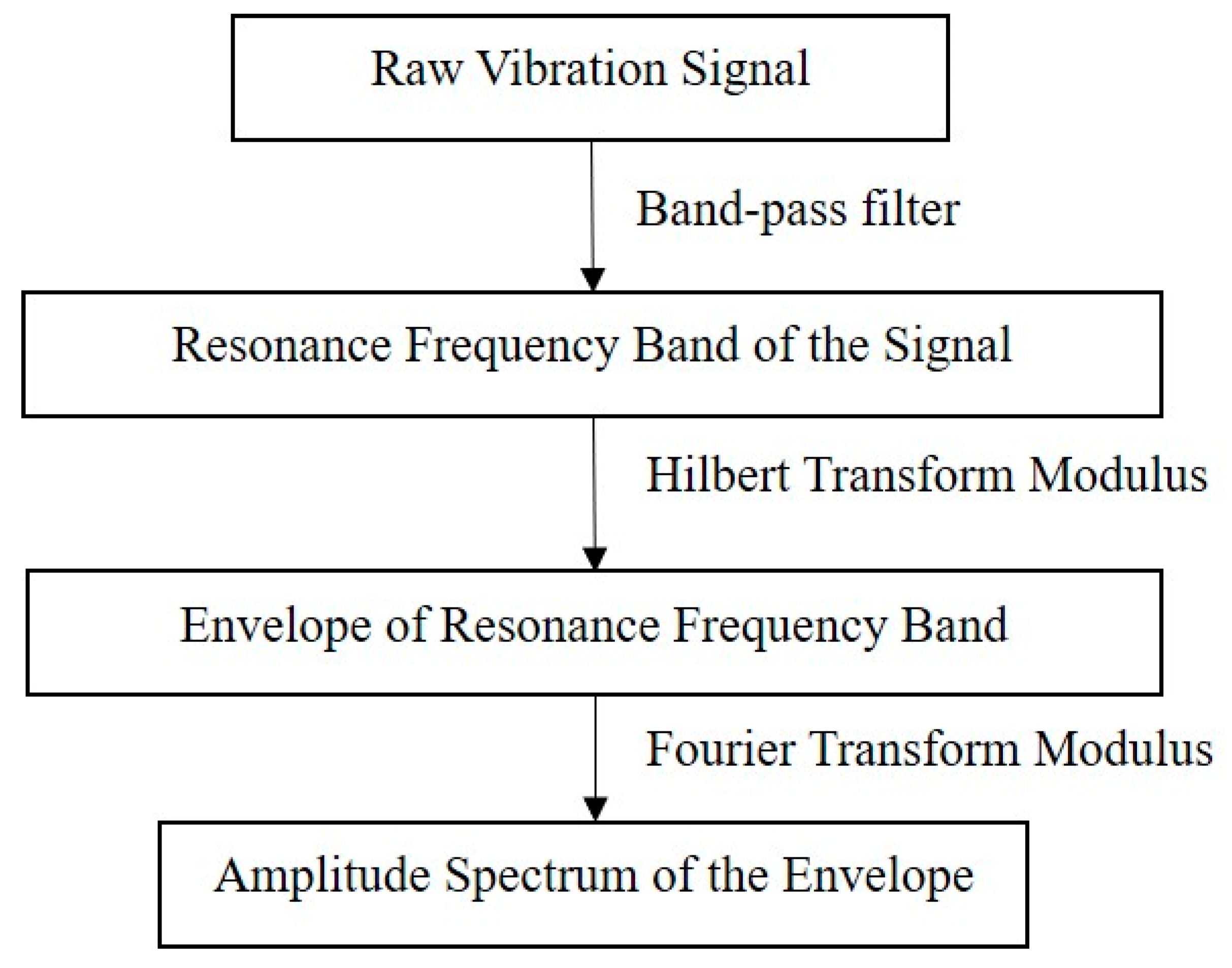
According to Randall [16], in bearing fault analysis, the raw vibration signal spectrum often contains insufficient information for a good diagnosis and, so, envelope analysis must be applied. As shown in Figure 1, in the envelope approach, the signal is filtered in the high frequency range, next to resonance, where the impact pulses are amplified. The resulting signal is amplitude demodulated by the modulus of Hilbert Transform, producing the envelope signal, whose amplitude spectrum is obtained by the modulus of the Fourier transform. The amplitude spectrum of the envelope signal presents the diagnostic information as spectral components at the characteristic frequencies of the bearing elements.
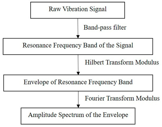
Figure 1.
Envelope analysis with the Hilbert and Fourier transforms.
3. Bearing Fault Detection by the Current Signature Analysis
In a running induction motor with a localized roller bearing fault, every time the faulty surface touches other elements, an impulse is generated. The associate frequency of this fault is proportional to the axis speed and to the bearing constructive aspects and, when in the outer race (BPFO), for instance, it is determined by [21]:
where Nb is the number of the balls, fr is the axis velocity, d is the ball diameter, D is the pitch diameter, and α is the bearing contact angle.
Riley [22] reported the relationship between the vibration signal and the stator current signal of an induction motor in the frequency domain by means of their respective spectra. Two models describe bearing fault detection in the current spectrum: the radial displacement model, and the torque variation model. Schoen [21] showed that the stator currents are amplitude modulated by the radial displacement produced by the bearing fault, resulting in the appearance of lateral components around the supply frequency in the spectrum. Their frequencies are expressed by:
where fe is the power supply frequency and m is a positive integer referring to the vibration component harmonic.
According to the torque variation model, Blodt [7] describes that bearing faults cause oscillations in the induction motor torque and consequently on its shaft speed. Torque oscillations result in RMS current oscillations and, consequently, instantaneous current modulation, also resulting in lateral components around the supply frequency in the spectrum.
4. Proposition Demonstration and Experimental Results
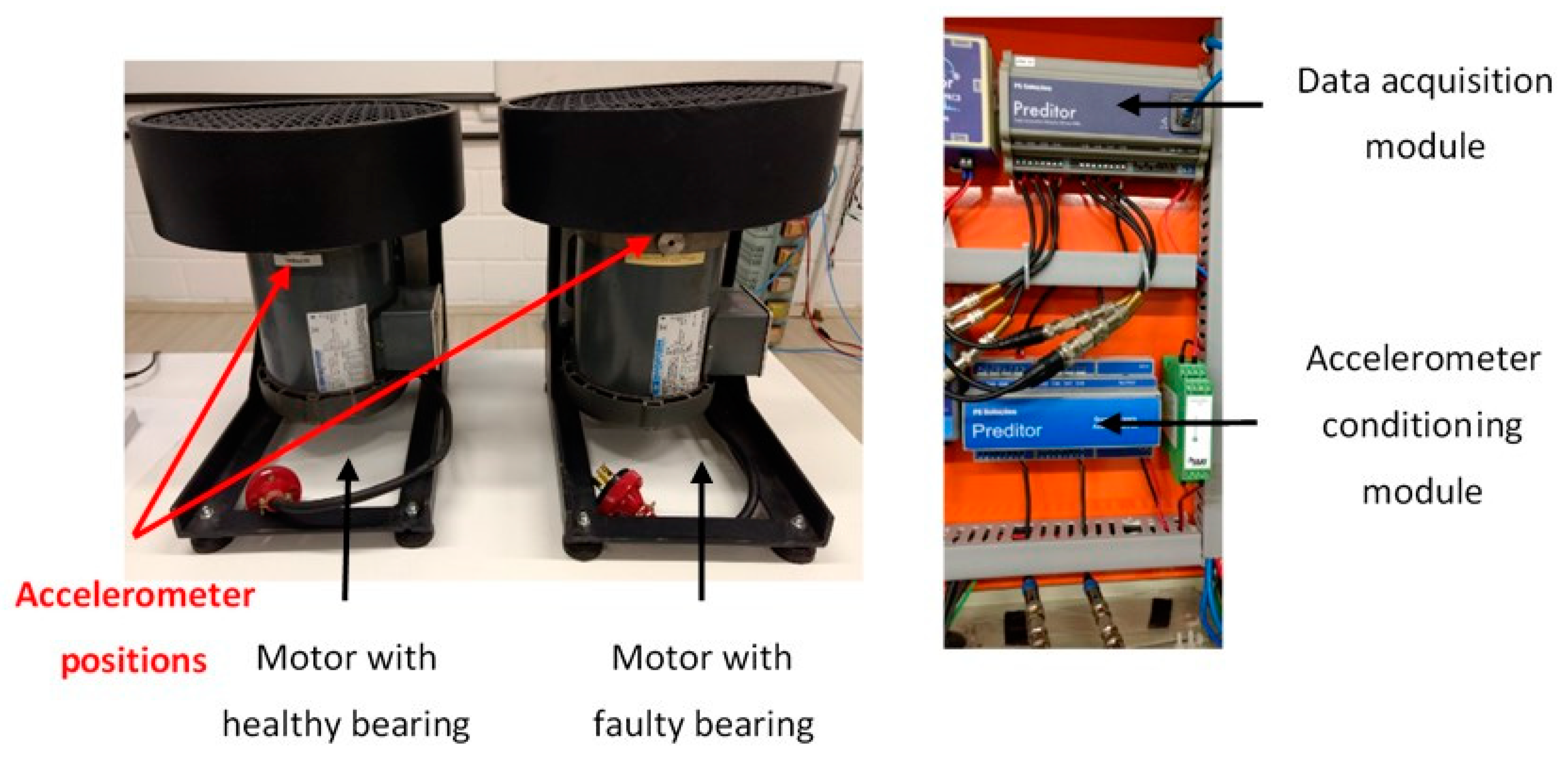
In this work, it is proposed to use envelope analysis as a first step for aiding the current spectrum characterization. The proposed approach is tested in a laboratory setup. A motor with healthy bearings and a motor with a localized bearing fault in the outer race of the driven end were prepared, as presented in Figure 2. The fault, of artificial origin, as addressed in other studies related to bearing faults [2,23,24], is applied to the bearing by means of a surface irregularity created in the outer race. To generate this irregularity on the surface, electric current was passed through the bearing until it could be felt slightly by turning the bearing in hands.

Figure 2.
Laboratory test setup.
The bearing model is 6203zz, with nominal BPFO of 3.066. The motor used in the test is a Marathon® 0.5 hp, three-phase, squirrel cage, induction motor. The motor is Y-closed, it has 2 poles, and it is fed by an inverter at 60.066 Hz. The load is a 6-blade fan coupled directly to the rotor shaft.
A current transducer (100mV/A), a monoaxial accelerometer (100 mV/g) and a 24bit data acquisition module were used for current and acceleration signal acquisition at a sample rate of 46.875 kSps. The signals were sampled during 60 seconds which implies a spectral resolution of 0.0167 Hz.
4.1. Vibration Analysis
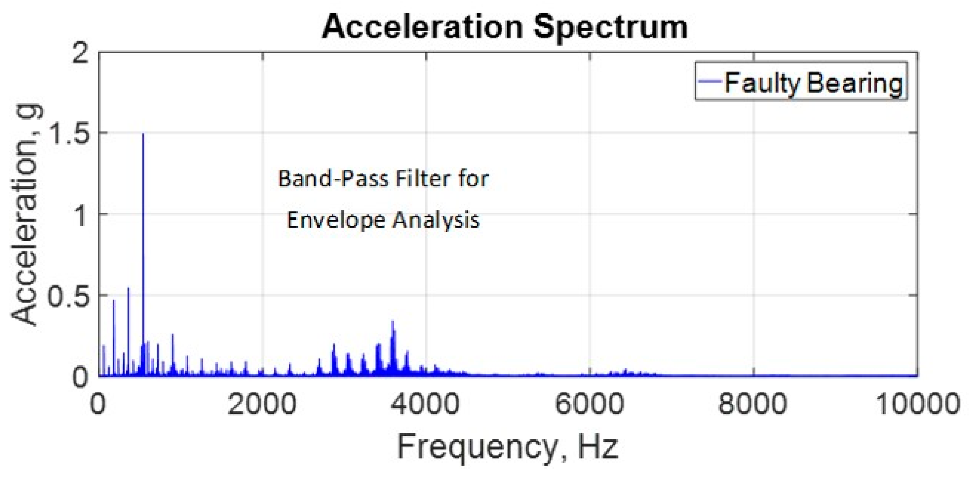
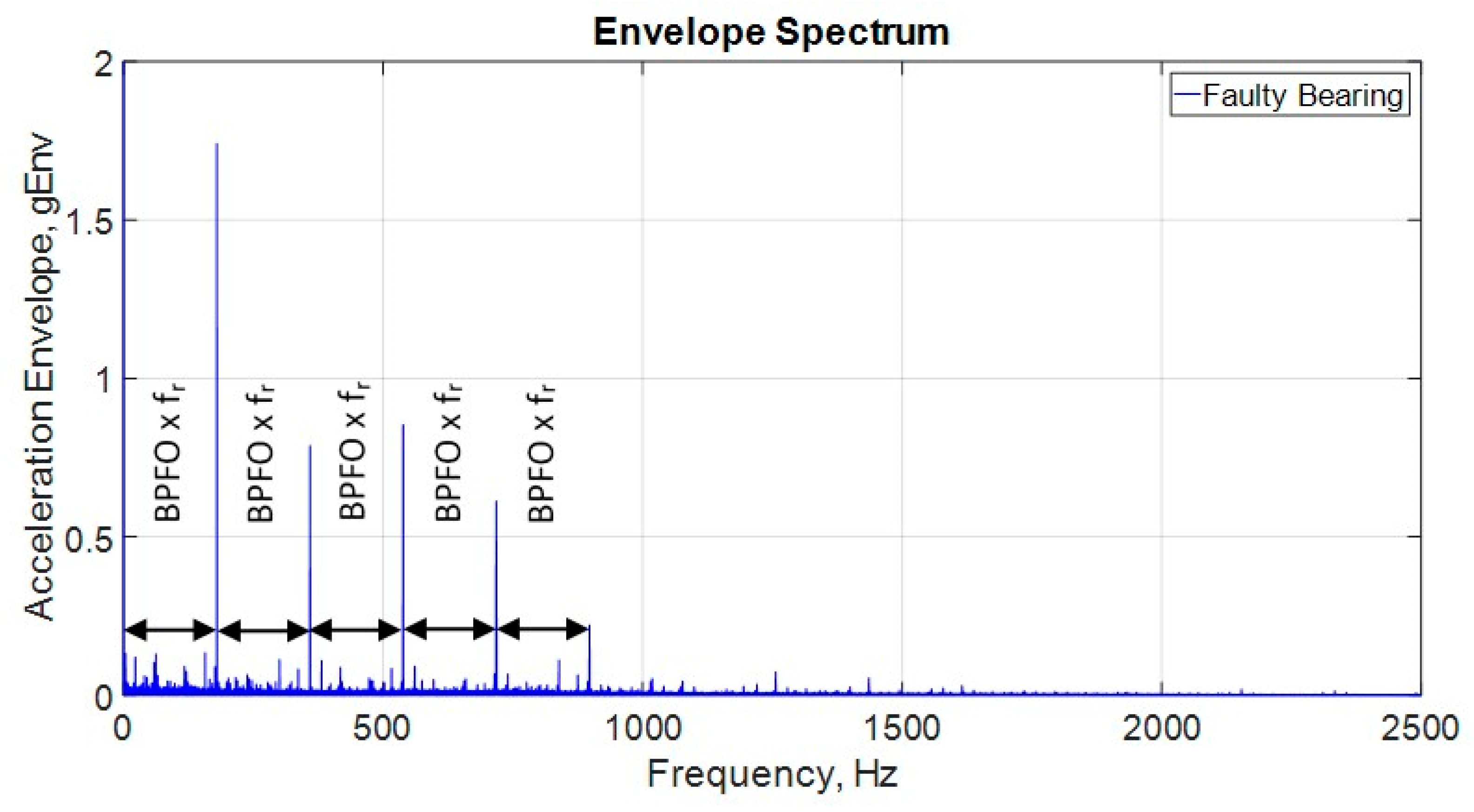
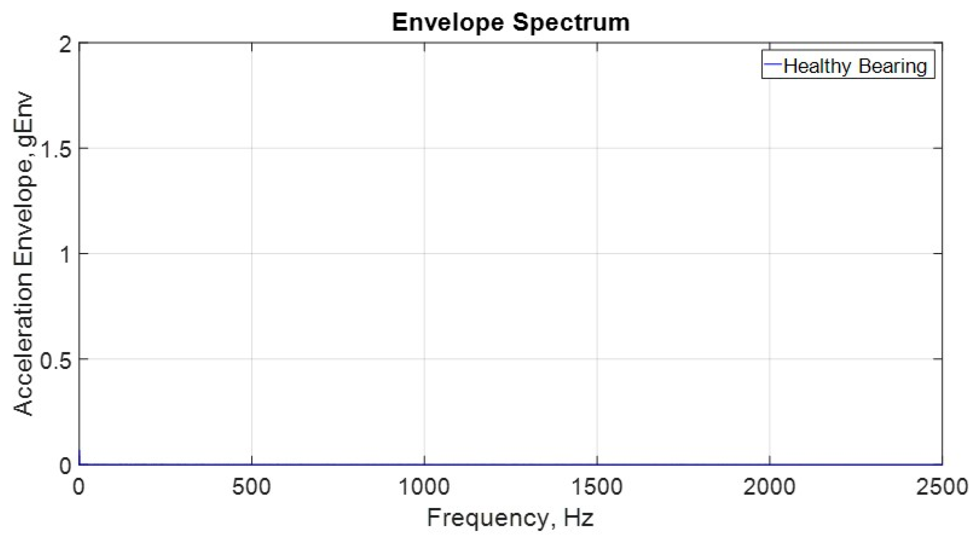
The acceleration spectrum for the faulty bearing is presented in Figure 3. Based on this spectrum, the band pass filter for the envelope analysis is set from 2000 Hz to 5000 Hz. Figure 4 presents the resulting envelope spectrum for the faulty bearing, where BPFO x fr harmonics are very clear. Figure 5 presents the resulting envelope spectrum for the healthy bearing, and it is clear that no BPFO x fr harmonics are present.
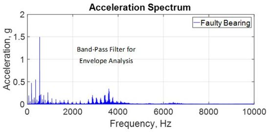
Figure 3.
Acceleration spectrum for the faulty bearing.
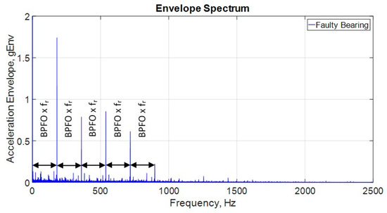
Figure 4.
Acceleration envelope spectrum for the faulty bearing.
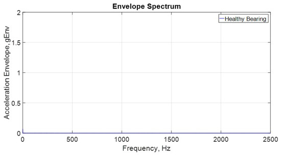
Figure 5.
Acceleration envelope spectrum for the healthy bearing.
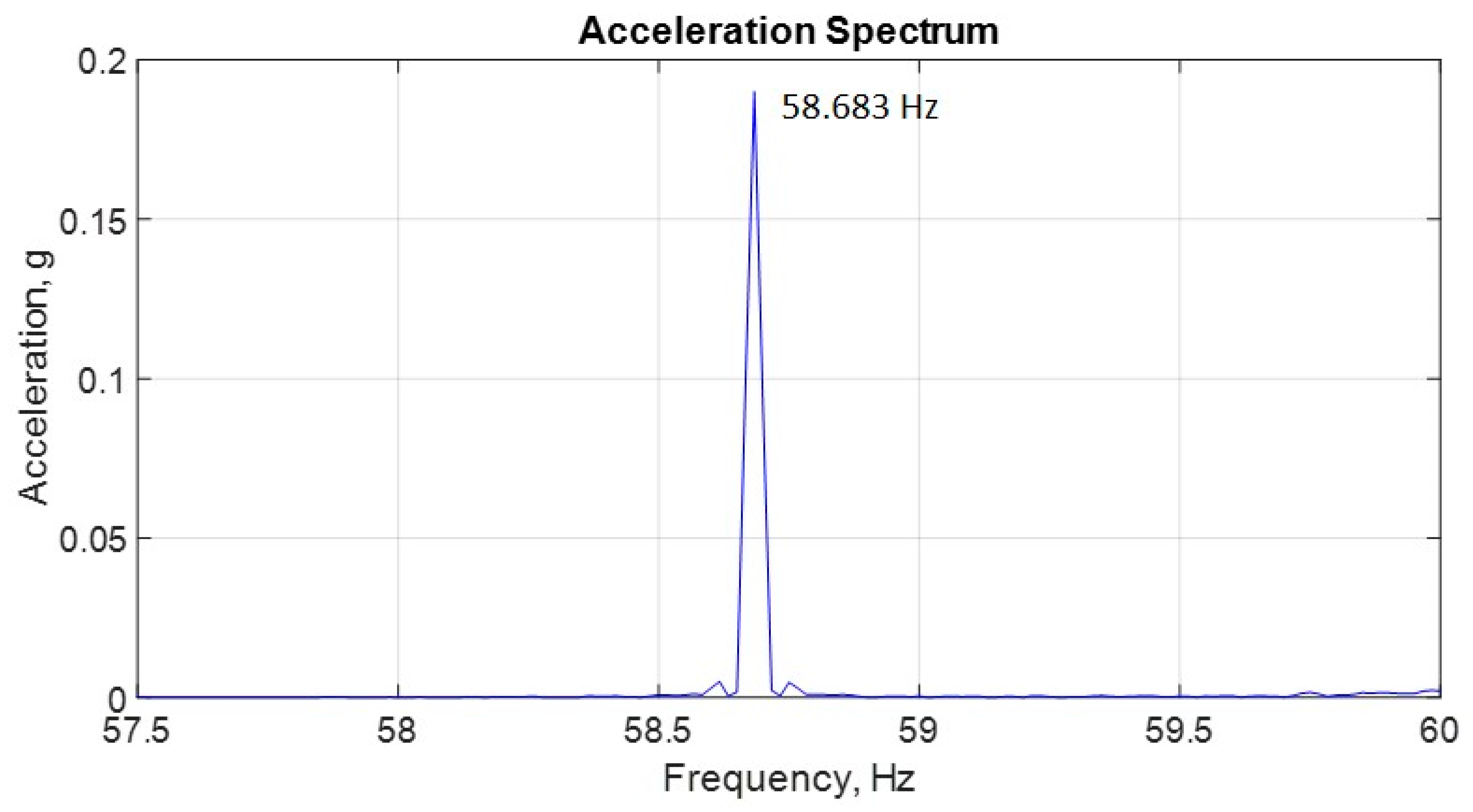
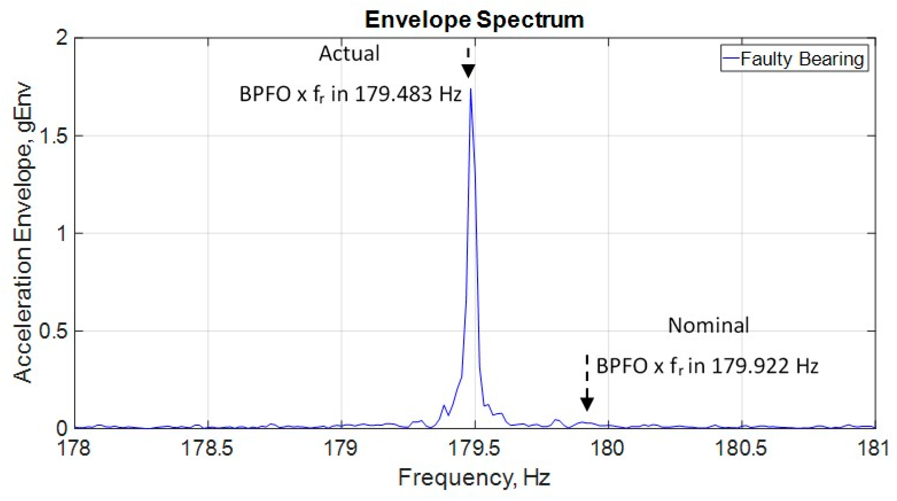
Figure 6 presents the acceleration spectrum with zoom in the shaft frequency component, fr, in 58.683 Hz. And Figure 7 shows the envelope spectrum with zoom in BPFO x fr in 179.483 Hz. The analysis of Figure 3 and Figure 4 can attest, as stated by Randall [16], that the acceleration envelope spectrum is the best tool for achieving a good diagnosis regarding localized roller bearing faults. Even more, based on the determination of fr and BPFO x fr from those high-resolution spectra presented in Figure 6 and Figure 7, it is possible to conclude that the actual value for BPFO is 3.059 (179.483 Hz/58.683 Hz) and not the nominal value of 3.066. If the nominal value would be considered, BPFO x fr frequency would be 179.922 Hz, as presented in Figure 7, a 0.439 Hz difference from the actual value. This difference can have many causes such as: geometric variations imposed by the failure itself, incorrect bearing installation, cage locking, improper lubrication and ball slip, for instance.
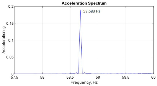
Figure 6.
Vibration signal showing the shaft velocity component for the faulty Bearing in 58.683 Hz.
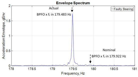
Figure 7.
Acceleration envelope spectrum with zoom in the actual BPFO x fr in 179.483 Hz.
4.2. Current Analysis
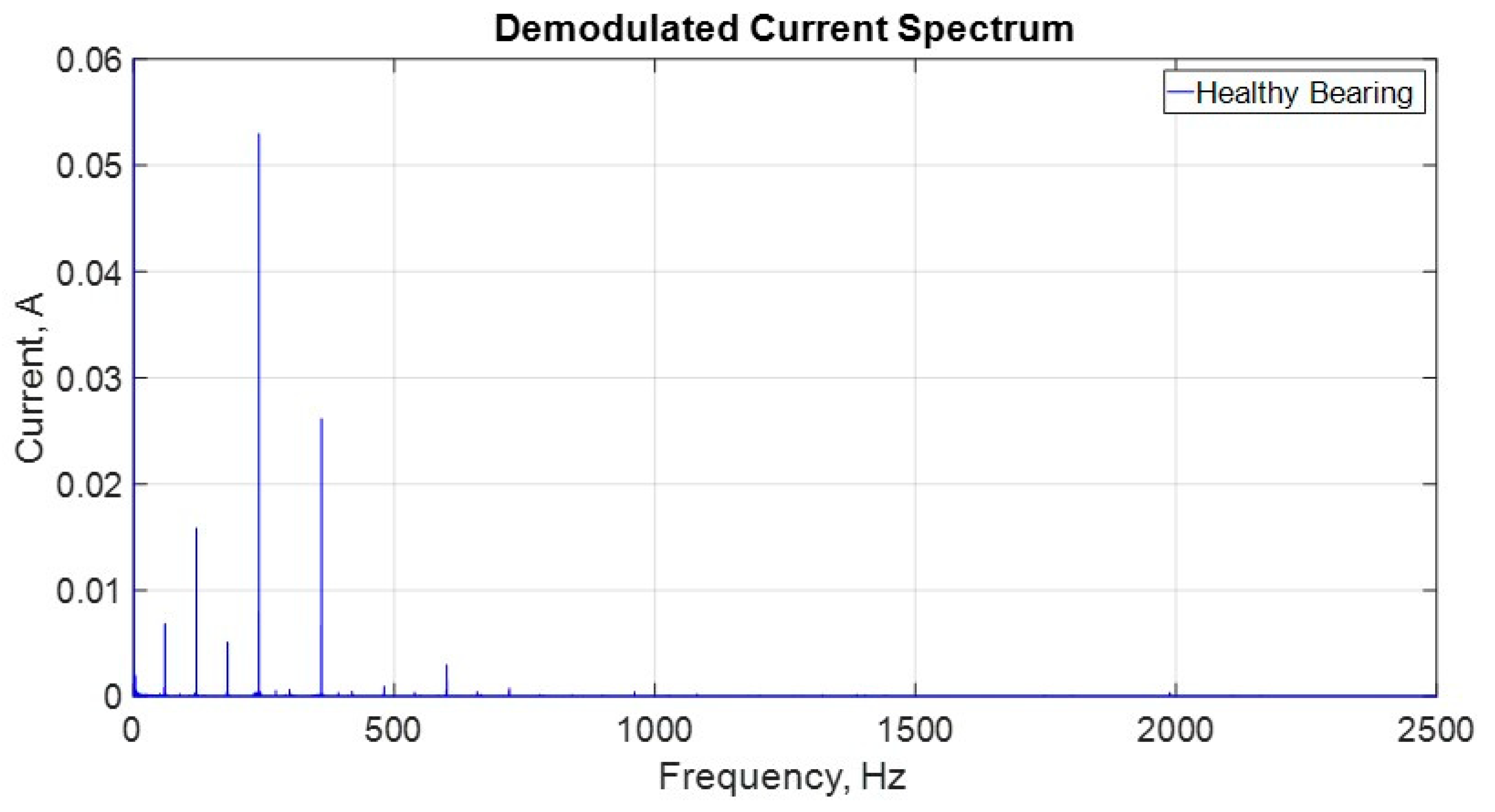
The demodulated stator current spectrum is shown in Figure 8 for the motor with a faulty bearing. The demodulated current (or the current envelope) is chosen to facilitate the comparison with the acceleration envelope spectrum. Current demodulation is performed applying the Hilbert transform modulus to the current signal without any band-pass filtering. As well, Figure 9 presents the demodulated stator current spectrum for the motor with a healthy bearing. In both spectra, the only components standing out are the supply frequency harmonics, having no relation to the bearing fault spectral components.
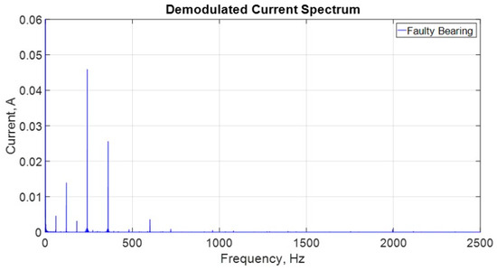
Figure 8.
Demodulated current spectrum for the motor with a faulty bearing.
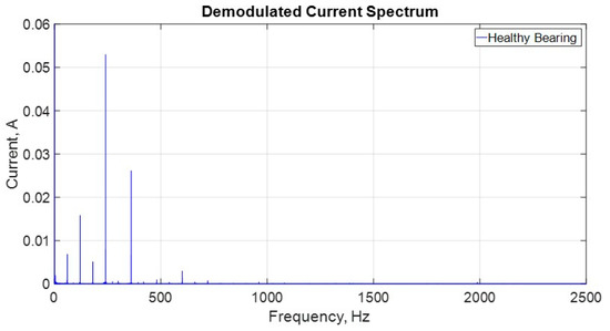
Figure 9.
Demodulated current spectrum for the motor with a healthy bearing.
On the other hand, Figure 10 presents the zoom of demodulated current for the motor with a faulty bearing in the region around BPFO x fr and it is possible to see a small peak exactly at frequency 179.483 Hz, as indicated by the acceleration envelope of the faulty bearing. Other peaks are present and can be associated to the inverter supply frequency harmonics (3 x fe), to the mains frequency harmonics (3 x f1) and even to rotor cage electric imbalance harmonics (3 x fe – s x fe, where s is the rotor slip), reinforcing the importance of envelope analysis for an effective diagnosis. The nominal BPFO x fr frequency is also pointed in Figure 9, showing that it must not be considered, as it leads to misinterpretation of the current spectrum and, consequently to a wrong diagnosis.
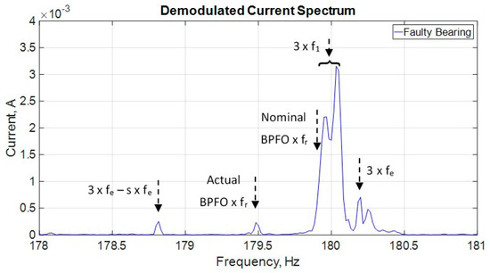
Figure 10.
Demodulate current signal spectrum with zoom around the actual BPFO x fr frequency.
Thus, the proposition of using the acceleration envelope as an aid tool for the characterization of the current spectrum in a first approach is very valid. After this first approach, with a well-known current spectrum, the tracking of the localized bearing faults over time can be carried on only by the MCSA technique itself, saving time and resources.
5. Proposition of a Self-Supplied Wireless Current Transducer—SSWCT
In recent times, new scenarios have emerged based on technological advances in two areas mainly, which are the development of microprocessors with high processing power and high efficiency; and the development of wireless communication protocols with high transfer rates and low consumption. These advances have stimulated a revolution in the world of sensors that have been called IoT (Internet of Things), where it is seen that all devices will present, in the near future, some kind of intelligence and interconnection through the Internet. In the industrial environment, another revolution related to these technological advances has been establishing, the so-called fourth Industrial Revolution, or Industry 4.0, where the physical systems of the factory floor will have their parameters monitored and digital models of their operative and maintenance condition will be updated for decision-making and optimization purposes.
Thus, in line with these innovative trends, to implement the MCSA approach describe in the sections above, it is proposed a Self-Supplied Wireless Current Transducer—SSWCT. A proof of concept of this proposed device was implemented in a Research and Development project for MCSA monitoring of induction motors and it is being tested in Pimental Hydroelectric power plant (at Belo Monte Complex, in north region of Brazil) for monitoring motors driving pumps of the cooling and speed regulator systems of the plant.
The concept of the SSWCT eliminates the use of external power modules, cables and batteries. Along with a wireless (IEEE 802.11 standard [20]) communication interface, it constitutes a completely galvanically insulated device, since there is no electric contact to the plant electric system. It is capable of transmitting the current signals to an analysis software as a digital wireless transducer, but it also has enough processing power and mass memory for digital signal processing tasks and data-logging, in order to operate as a stand-alone device.
The SSWCT harvests its power from the magnetic field of the same currents it is transducing. For that, it uses current transformers with high permeability magnetic material cores, optimized for power extraction.
The main advantage of this concept is the ease of installation, for it is a self-contained device that can be installed in the motor cables, saving space in the motor control center panels. The implemented device can monitor one motor current with its built-in measurement current transformer or two motor currents, using an external current transformer connected to the main module.
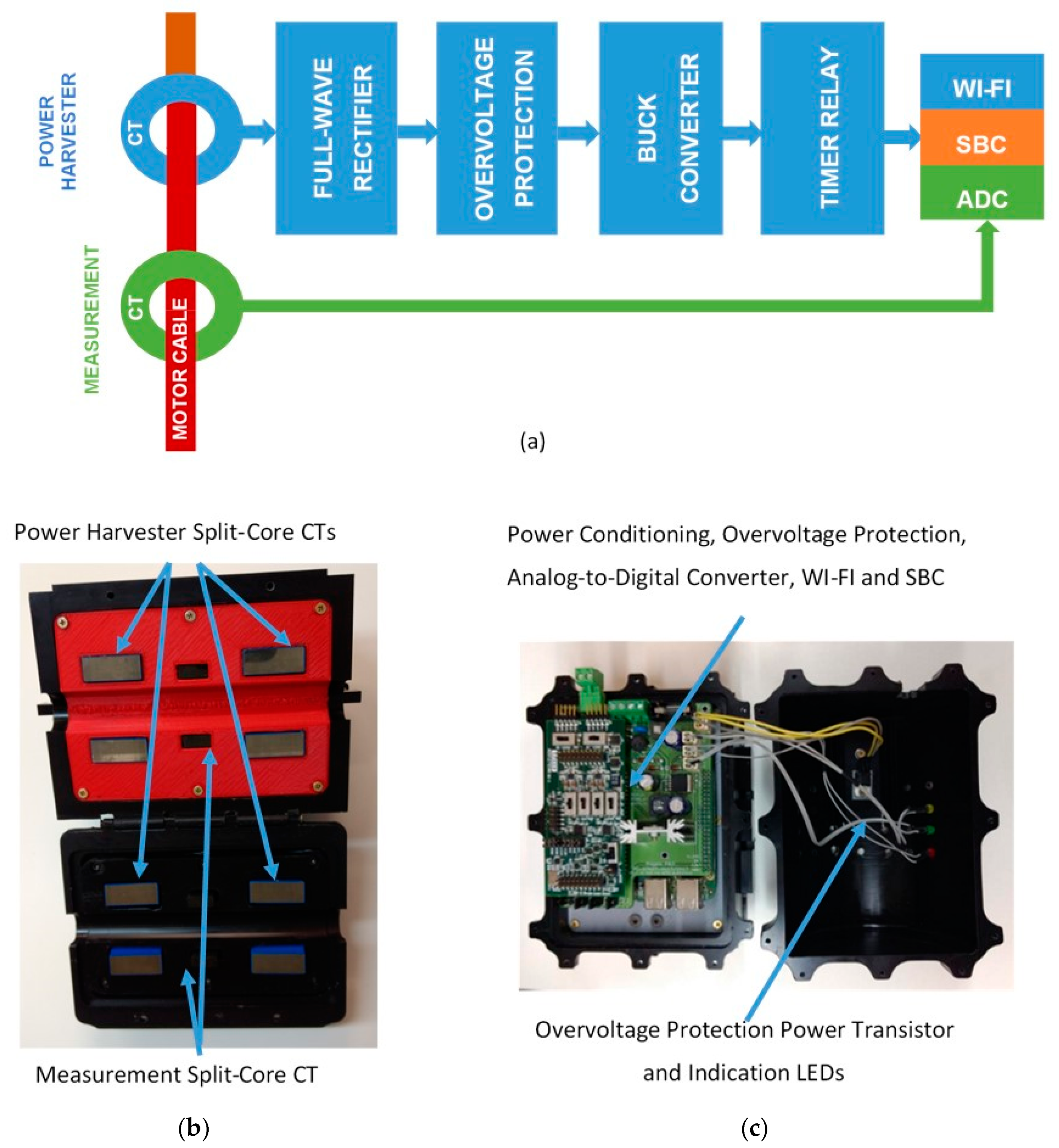
Figure 11 presents the concept device developed by the authors. In the block diagram, presented in Figure 11a, the Power Harvester Current Transform (CT) outputs the power in AC form, the Full-Wave Rectifier transforms it to DC form, the Overvoltage Protection clamps the voltage to the limit of the Buck Converter input and the Buck Converter steps down and regulate the voltage to a Timer Relay, that will power the application only after a preset delay to avoid transients. The application is a Single Board Computer with a Wi-Fi module and a 24-bit ADC. The application digitalizes the current measured by the Measurement CT and processes, stores and transmits it to the software application for analysis and log.

Figure 11.
SSWCT: (a) SSWCT block diagram; (b) power harvester and measurement CTs the case; and (c) electronic circuit boards and components in the open case.
The block diagram in Figure 11a presents only one power harvester CT, but two CTs (Figure 11b) are used in order to achieve the minimum operating current of 35 A, stablished as a design constraint. As well, two measurement CTs can be used: an internal one, shown in Figure 11b and an external one, not shown.
In the design process of the Power Harvester CTs, the main constraints were: the magnetic core size (outer diameter 55 mm, inner diameter 31 mm and height 30 mm), the minimum current for operation (~ 35 A), and the maximum load power (~ 2.5 W). The magnetization curve for the chosen core were determined and used in a simulation model to optimize the number of secondary winding turns to provide the maximum load power in the minimum current condition.
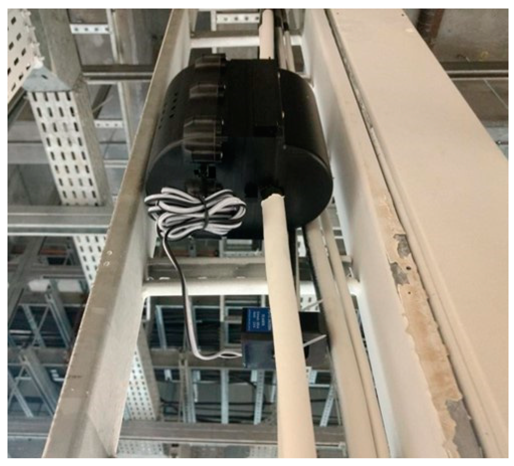
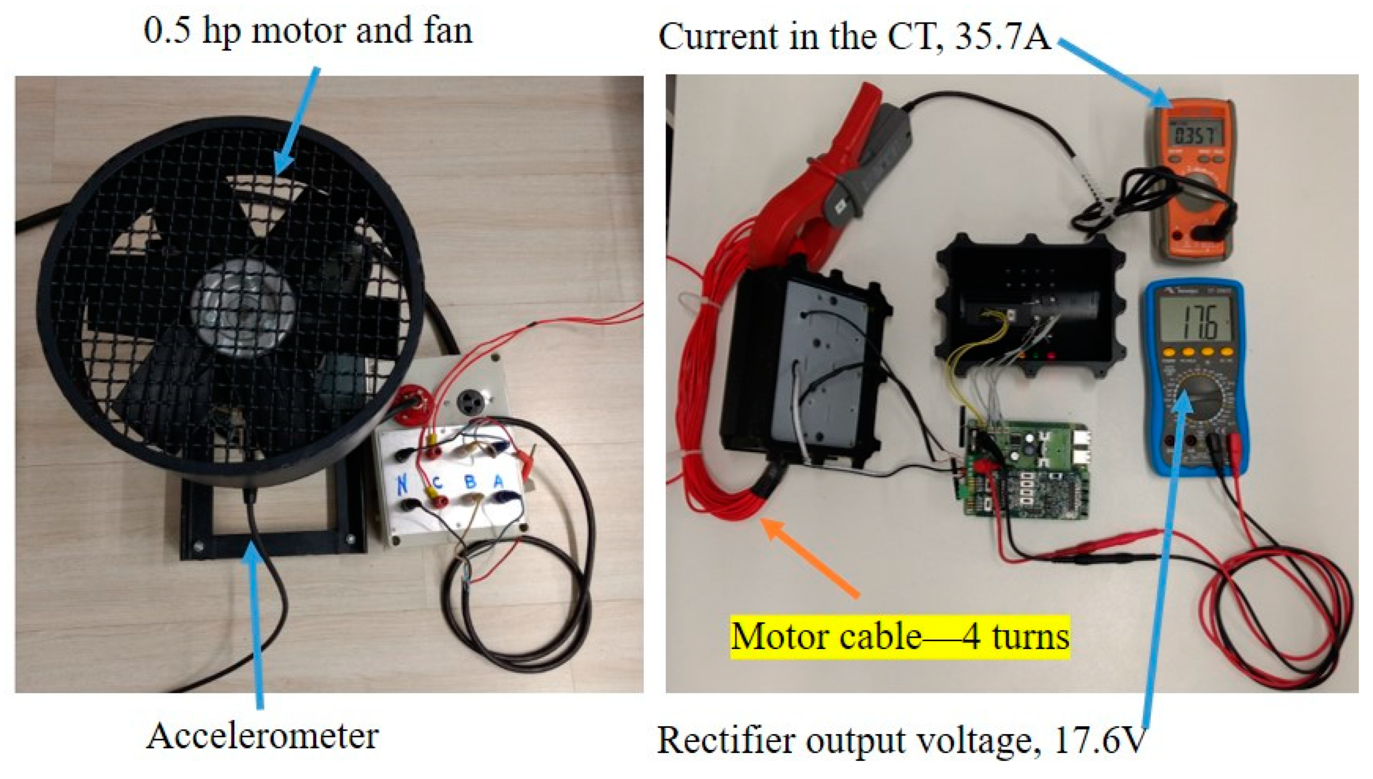
Figure 12 presents the SSWCT installed in a motor cable at Pimental power plant. The second and external CT, mentioned above, can be seen in the picture. Once the installation at Pimental is very recent and interesting results regarding roller bearing faults have not been collected yet, a test setup for the SSWCT is presented in Figure 13. The SSWCT is presented open for test measurements. The supply current of the motor-fan assembly is about 1.5 A in 220V and 60Hz. The SSWCT was designed to operate with a minimum of 35 A. So, to operate the SSWCT with such a small laboratory motor, 24 turns were passed through the CT, producing a magnetomotive force of ~36 A.turn (~1.5 A x 24 turns). Of course, the current measured is divided by 24 in the software to yield the correct value. In the figure, the primary current, 35.7 A, is shown in the orange multi-meter and the rectified voltage, 17.6 Vdc, in the output of the power harvester is presented in the blue multi-meter. The motor current is measured by the internal current transformer of the SSWCT and the accelerometer output is measured by the data acquisition module presented in Figure 2.

Figure 12.
SSWCT with its second measurement current transformer installed at Pimental power plant in the north region of Brazil.
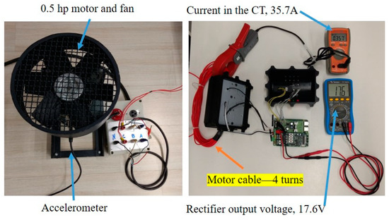
Figure 13.
Test setup for the SSWCT.
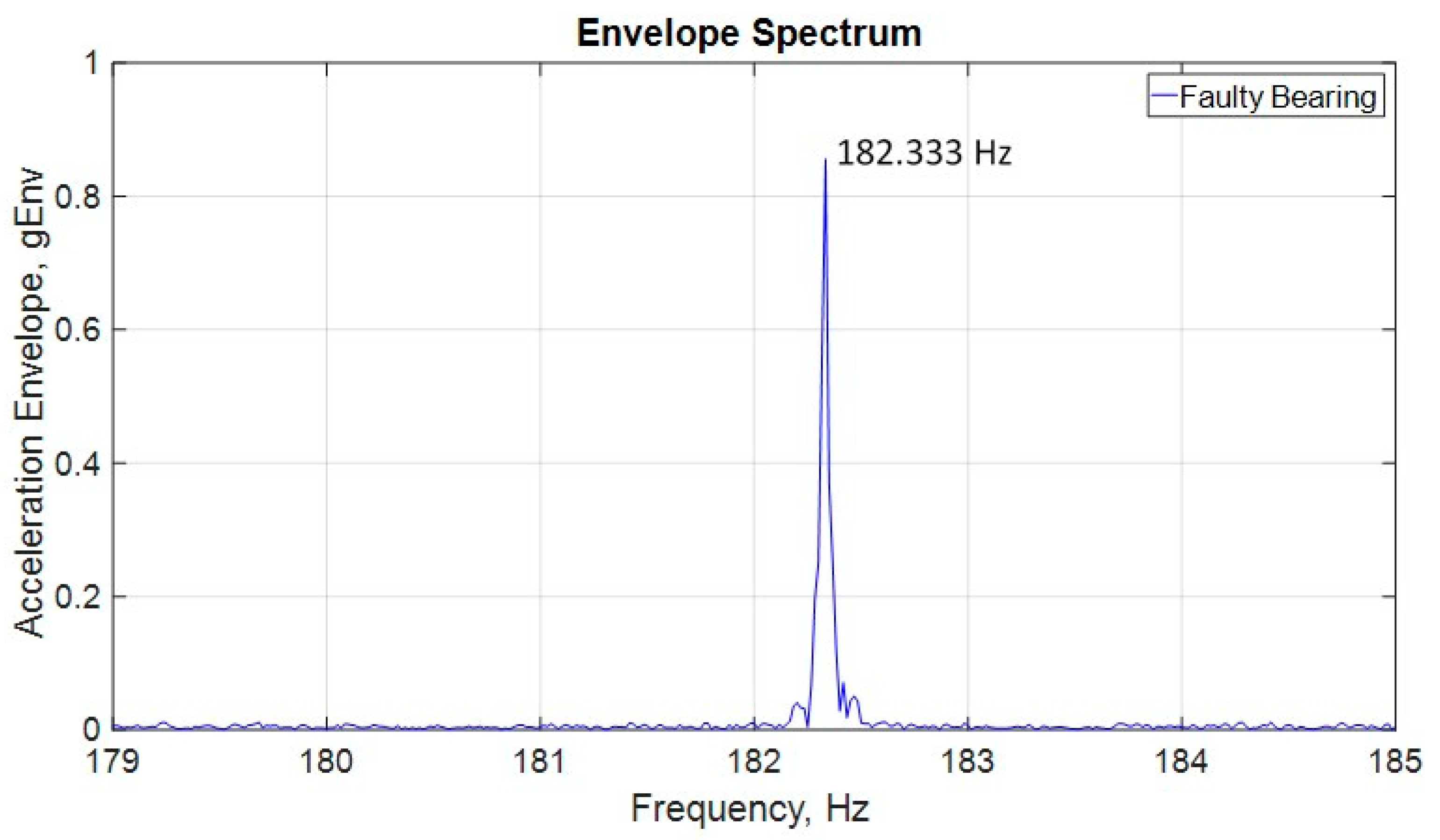
Figure 14 presents the acceleration envelope analysis of a test run, showing the actual BPFO x fr frequency, 183.333 Hz.
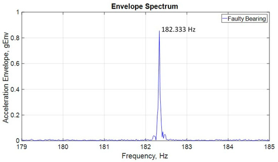
Figure 14.
Acceleration envelope spectrum with zoom in the actual BPFO x fr.
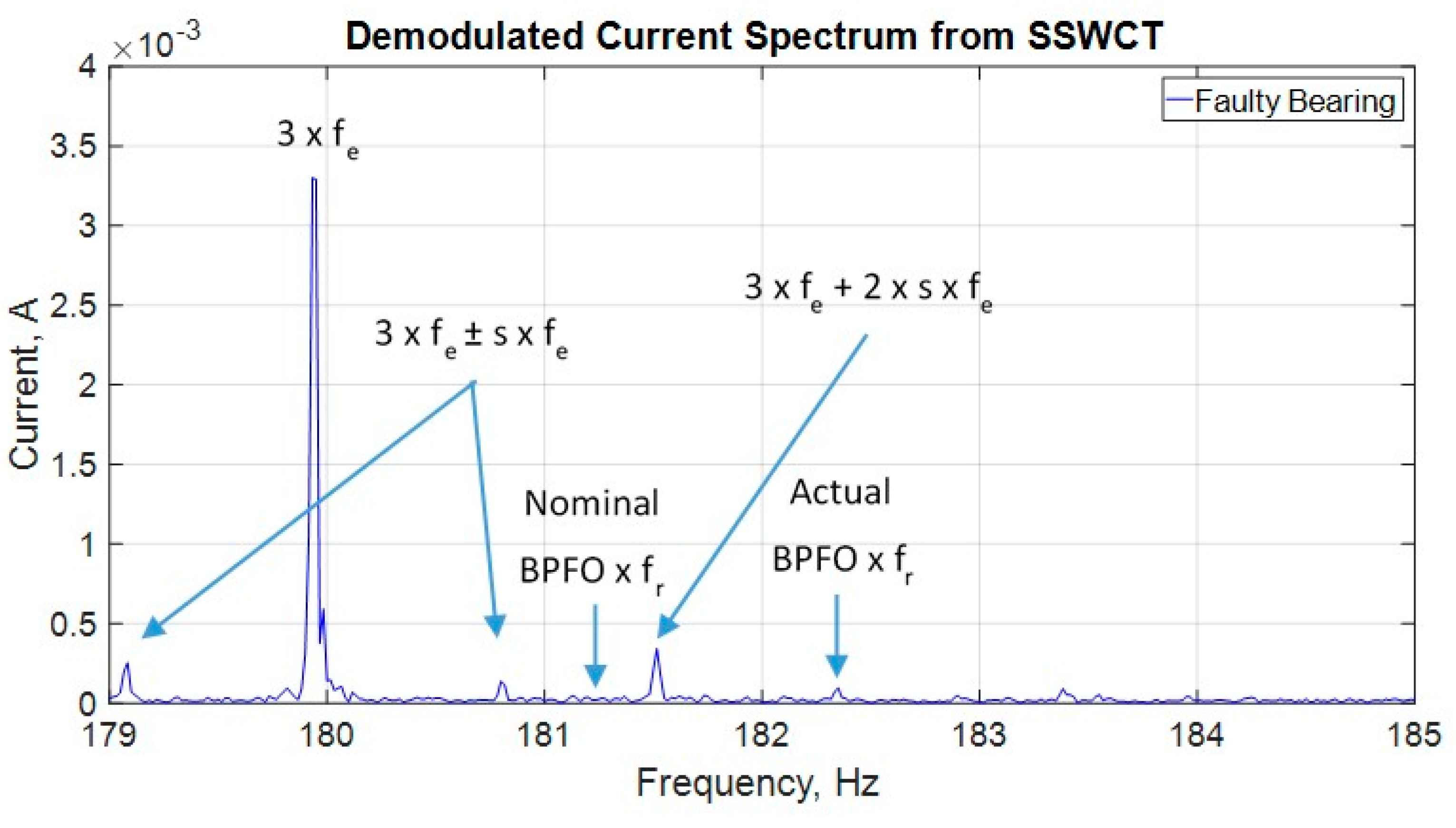
Figure 15 presents the demodulated current spectrum produced using the SSWCT, where a small peak at the same frequency of the dominant peak, shown in the acceleration envelope spectrum, can be seen. This test, and others performed in the laboratory, shows that the SSWCT presents the same functionality of a traditional data acquisition system used for motor current signature analysis. For this run, the rotor frequency, fr, is 59.117 Hz. It is curious to notice that, after many hours running, the actual BPFO for this run is 3.084 (182.333/59.117), against the nominal value 3.066, showing once more the elusive nature of this “constant” and highlighting the importance of the use of acceleration envelope spectrum as a reference for bearing fault studies in the motor current signature analysis.
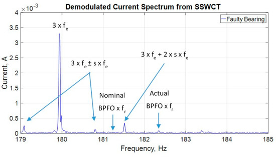
Figure 15.
Demodulated current signal spectrum with zoom around the actual BPFO x fr frequency.
6. Conclusions
This paper proposes the use of vibration envelope analysis as an aid tool for the accurate determination of the characteristic frequencies of localized bearing faults in the stator current spectrum of three-phase induction motors. The methodology is described and demonstrated with real current and acceleration signals. Motors with healthy and faulty roller bearings are prepared for laboratory experiments. After this first current spectrum characterization with the aid of envelope analysis, the MCSA technique can carry on with the analysis over time in order to exploit its advantages.
The complexity of the current spectrum is presented in order to justify the proposed approach. It is shown that many spectrum components of diverse nature can coexist in a very narrow region in the spectrum and their characterization can be tricky. This way, at least in a first stage, the use of an aid tool like vibration and envelope analysis is necessary for an assertive bearing fault diagnosis.
Finally, in line with the recent trends in IIOT, Industry 4.0 and energy harvesting, the concept of a Self-Supplied Wireless Current Transducer—SSWCT is proposed as a means for implementing MCSA monitoring in a modern way, including the proposed methodology described in the first part of the paper. A proof-of-concept implementation of the SSWCT is presented as well as its experimental use in a power plant in north of Brazil.
Author Contributions
I.A.d.S.A., L.E.B.d.S., and E.L.B. conceived and designed the experiments; I.A.d.S.A., L.E.B.d.S., E.L.B., L.E.d.L.d.O., G.L.-T., and V.A.B. performed the experiments; I.A.d.S.A., L.E.B.d.S., E.L.B., L.E.d.L.d.O., and V.A.B. analyzed the data; L.E.B.d.S., E.L.B., L.E.d.L.d.O., and G.L.-T. contributed analysis tools; and I.A.d.S.A., and G.L.-T. wrote the paper.
Funding
This research received no external funding.
Acknowledgments
The authors would like to thank the National Council for Scientific and Technological Development (CNPq), Coordination for the Improvement of Higher Education Personnel (CAPES) and Brazilian Electricity Regulatory Agency Research and Development (ANEEL R&D) for supporting this project.
Conflicts of Interest
The authors declare no conflict of interest.
Nomenclature
| Abbreviations | |
| AC | Alternate Current |
| ADC | Analog-to-Digital Converter |
| BPFO | Ball Pass Frequency – Outer Race |
| CT | Current Transformer |
| DC | Direct Current |
| MCSA | Motor Current Signature Analysis |
| SBC | Single Board Computer |
| SSWCT | Self-Supplied Wireless Current Transducer |
| Parameters | |
| d | Ball diameter |
| D | Pitch diameter |
| fbng | Vibration frequency |
| fc | Frequency of lateral components in the fundamental component |
| fe | Supply frequency |
| f1 | Mains frequency |
| fr | Shaft rotating frequency |
| s | Rotor slip |
| m | Positive integer referring to the vibration component harmonics |
| Nb | Number of balls |
| α | Bearing contact angle |
Appendix A. Rotor Frequency Measurement and BPFO Accuracy Consideration
The BPFO is a dimensionless “constant”. The nominal value of BPFO, denoted here by BPFOnominal, is given by the bearing manufacturer and it is given without accuracy information. The actual BPFO, denoted here by BPFOactual, is calculated, in this paper, based on the peak that arises in the envelope spectrum.
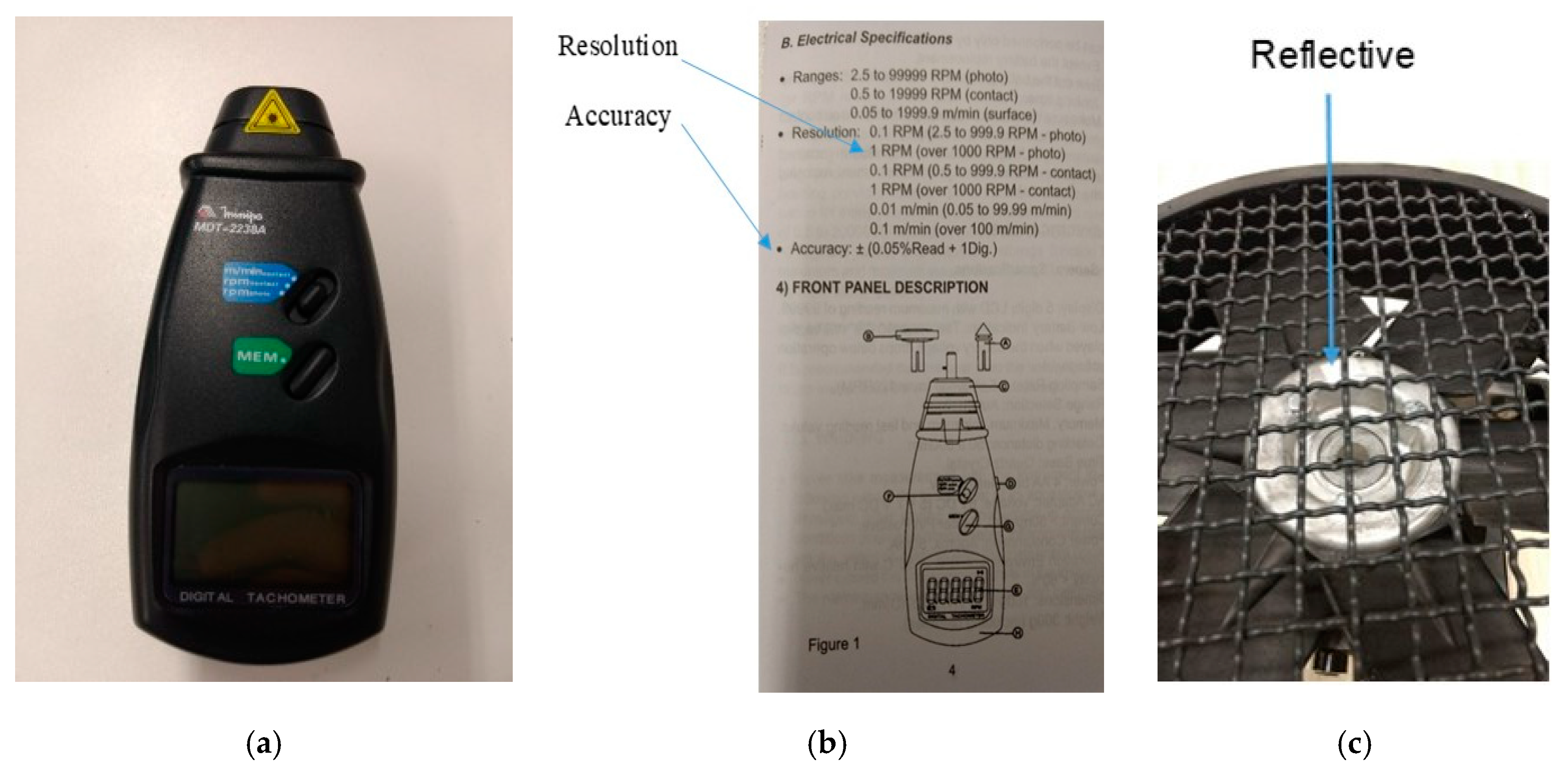
The frequency associated to each BPFO is (BPFO x fr), and fr is the rotor frequency. The rotor frequency measurement, fr, was performed with a photo tachometer, Figure A1, and refined by the high-resolution acceleration spectrum that was employed in the analyzes. According to the tachometer specification (informed in the figure bellow), the accuracy of a 3520 RPM reading is ± 3 RPM (3520 × 0.05/100 + 1). Hence, according to the tachometer, the rotor frequency is in the range of 58.667 Hz ± 0.046 Hz (since 1 Hz = 60 RPM).
The acceleration spectrum shows a peak at 58.683 Hz (Figure 6), just in the range of the tachometer reading. Of course, the peak frequency is not the real frequency, since it is the center of a discrete frequency bin. The real frequency is in the range of the peak frequency ±Δf/2, where Δf is the spectral resolution. The spectral resolution is the inverse of the acquisition time. As informed in the paper, the acquisition time is 60 s. So, Δf/2 = 0.008 Hz ((1/60)/2). Hence, by the spectrum, the real rotor frequency is in the range of 58.683 Hz ± 0.008 Hz, which is adequate to the proposed analysis.
So, BPFOnominal x fr is in the range of 179.922 Hz ± 0.025 Hz (3.066 x (58.683 Hz ± 0.008 Hz)). On the other hand, BPFOactual x fr is determined by the dominant peak in the vibration envelope spectrum ± Δf/2, Figure 7, and, so, BPFOactual = 3.05852 ± 0.00055 ((179.483 Hz ± 0.008 Hz)/(58.683 Hz ± 0.008 Hz)).
Hence, by the above stated, the differences between BPFOnominal (3.066) and BPFOactual (3.05852 ± 0.00055) are significant and supported by the measurement accuracy.
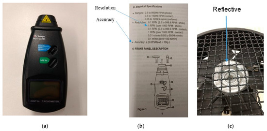
Figure A1.
Photo tachometer: (a) picture of the photo tachometer used in the setup; (b) specifications of the photo tachometer used; and (c) Reflective Tape used in the setup.
Figure A1.
Photo tachometer: (a) picture of the photo tachometer used in the setup; (b) specifications of the photo tachometer used; and (c) Reflective Tape used in the setup.
References
- Zhang, P.; Du, Y.; Habetler, T.G.; Lu, B. A survey of condition monitoring and protection methods for medium-voltage induction motors. IEEE Trans. Ind. Appl. 2011, 47, 34–36. [Google Scholar] [CrossRef]
- Immovilli, F.; Bianchini, C.; Cocconcelli, M.; Bellini, A.; Rubini, R. Bearing fault model for induction motor with externally induced vibration. IEEE Trans. Ind. Electron. 2013, 60, 3408–3418. [Google Scholar] [CrossRef]
- Prieto, M.D.; Cirrincione, G.; Espinosa, A.G.; Ortega, J.; Henao, H. Bearing fault detection by a novel condition-monitoring scheme based on statistical-time features and neural networks. IEEE Trans. Ind. Electron. 2013, 60, 3398–3407. [Google Scholar] [CrossRef]
- Salomon, C.P.; Santana, W.C.; Lambert-Torres, G.; Borges da Silva, L.E.; Bonaldi, E.L.; de Oliveira, L.E.L.; Borges da Silva, J.G.; Pellicel, A.; Figueiredo, G.C.; Lopes, M.A.A. Discrimination of Synchronous Machines Rotor Faults in Electrical Signature Analysis based on Symmetrical Components. IEEE Trans. Ind. Appl. 2017, 53, 3146–3155. [Google Scholar] [CrossRef]
- Fu, L.; Zhu, T.; Zhu, K.; Yang, Y. Condition Monitoring for the Roller Bearings of Wind Turbines under Variable Working Conditions Based on the Fisher Score and Permutation Entropy. Energies 2019, 12, 3085. [Google Scholar] [CrossRef]
- Li, X.; Elasha, F.; Shanbr, S.; Mba, D. Remaining Useful Life Prediction of Rolling Element Bearings Using Supervised Machine Learning. Energies 2019, 12, 2705. [Google Scholar] [CrossRef]
- Blodt, M.; Granjon, P.; Raison, B.; Rostaing, G. Models for bearing damage detection in induction motors using stator current monitoring. IEEE Trans. Ind. Electron. 2008, 55, 1813–1822. [Google Scholar] [CrossRef]
- Bonaldi, E.L.; de Oliveira, L.E.L.; Borges da Silva, J.G.; Lambert-Torres, G.; Borges da Silva, L.E. Predictive maintenance by electrical signature analysis to induction motors. In Induction Motors—Modelling and Control; Araujo, R., Ed.; InTech: Rijeka, Croatia, 2012; pp. 487–520. [Google Scholar] [CrossRef]
- Bonaldi, E.L.; de Oliveira, L.E.L.; Borges da Silva, J.G.; Lambert-Torres, G.; Borges da Silva, L.E. Detecting load failures using the induction motor as a transducer. In Proceedings of the International Conference on Control, Automation, Robotics and Vision, Hanoi, Vietnam, 17–20 December 2008; pp. 196–199. [Google Scholar] [CrossRef]
- Immovilli, F.; Bellini, A.; Rubini, R.; Tassoni, C. Diagnosis of bearing faults in induction machines by vibration or current signals: A critical comparison. IEEE Trans. Ind. Appl. 2010, 46, 1350–1359. [Google Scholar] [CrossRef]
- Gong, X.; Qiao, W. Bearing fault diagnosis for direct-drive wind turbines via current-demodulated signals. IEEE Trans. Ind. Electron. 2013, 60, 3419–3428. [Google Scholar] [CrossRef]
- Chang, H.-C.; Jheng, Y.-M.; Kuo, C.-C.; Hsueh, Y.-M. Induction Motors Condition Monitoring System with Fault Diagnosis Using a Hybrid Approach. Energies 2019, 12, 1471. [Google Scholar] [CrossRef]
- Tavner, P.; Ran, L.; Penman, J.; Sedding, H. Condition Monitoring of Rotating Electrical Machines; The Institution of Engineering and Technology: London, UK, 2008. [Google Scholar]
- Elbouchikhi, E.; Choqueuse, V.; Amirat, Y.; Benbouzid, M.E.H.; Turri, S. An efficient Hilbert-Huang transform-based bearing faults detection in induction machines. IEEE Trans. Energy Conv. 2017, 32, 401–413. [Google Scholar] [CrossRef]
- Cusido, J.; Romeral, L.; Garcia, A.; Rosero, J.A.; Ortega, J.A. Fault detection in induction machines by using continuous and discrete wavelet decomposition. In Proceedings of the 2007 European Conference on Power Electronics and Applications, Aalborg, Denmark, 2–5 September 2007. [Google Scholar] [CrossRef]
- Randall, R.B. Vibration-Based Condition Monitoring; John Wiley & Sons Ltd.: New York, NY, USA, 2011. [Google Scholar]
- Salomon, C.P.; Santana, W.C.; Bonaldi, E.L.; de Oliveira, L.E.L.; Borges da Silva, L.E.; Borges da Silva, J.G.; Lambert-Torres, G.; Pellicel, A.; Lopes, M.A.A.; Figueiredo, G.C. A study of electrical signature analysis for two-pole synchronous generators. In Proceedings of the 2017 IEEE International Instrumentation and Measurement Technology Conference (I2MTC), Turin, Italy, 22–25 May 2017; pp. 1–6. [Google Scholar] [CrossRef]
- He, D.; Li, R.; Zhu, J. Plastic bearing fault diagnosis based on a two-step data mining approach. IEEE Trans. Ind. Electron. 2013, 60, 3429–3440. [Google Scholar] [CrossRef]
- Sui, W.; Zhang, D. Research on envelope analysis for bearings fault detection. In Proceedings of the International Conference on Computer Science & Education, Hefei, China, 24–27 August 2010; pp. 973–976. [Google Scholar] [CrossRef]
- IEEE Standard for Information Technology-Telecommunications and information exchange between systems Local and metropolitan area networks-Specific requirements Part 11: Wireless LAN Medium Access Control (MAC) and Physical Layer (PHY) Specifications Amendment 3: Enhancements for Very High Throughput to Support Chinese Millimeter Wave Frequency Bands (60 GHz and 45 GHz). In IEEE Std 802.11aj-2018 (Amendment to IEEE Std 802.11-2016 as amended by IEEE Std 802.11ai-2016 and IEEE Std 802.11ah-2016). 18 April 2018; 1–306. [CrossRef]
- Schoen, R.R.; Habetler, T.G.; Kamran, F.; Bartfield, R.G. Motor bearing damage detection using stator current monitoring. IEEE Trans. Ind. Appl. 1995, 31, 1274–1279. [Google Scholar] [CrossRef]
- Riley, C.M.; Lin, B.K.; Habetler, T.G.; Schoen, R.R. A method for sensorless on-line vibration monitoring of induction machines. IEEE Trans. Ind. Appl. 1988, 34, 1240–1245. [Google Scholar] [CrossRef]
- Bonnardot, F.; Randall, R.B.; Antoni, J.; Guillet, F. Enhanced unsupervised noise cancelation (E-SANC) using angular resampling—Application for planetary bearing fault diagnosis. In Proceedings of the 5th International Conference Acoustical and Vibratory Surveillance Methods and Diagnostic Techniques, Senlis, France, 11–13 October 2004; pp. 1–11. [Google Scholar]
- Salomon, C.P.; Ferreira, C.; Sant’Ana, W.C.; Lambert-Torres, G.; Borges da Silva, L.E.; Bonaldi, E.L.; de Oliveira, L.E.L.; Torres, B.S. A Study of Fault Diagnosis Based on Electrical Signature Analysis for Synchronous Generators Predictive Maintenance in Bulk Electric Systems. Energies 2019, 12, 1506. [Google Scholar] [CrossRef]


© 2019 by the authors. Licensee MDPI, Basel, Switzerland. This article is an open access article distributed under the terms and conditions of the Creative Commons Attribution (CC BY) license (http://creativecommons.org/licenses/by/4.0/).