Article

Air-Floating Characteristics of Large-Diameter Multi-Bucket Foundation for Offshore Wind Turbines

1
National Engineering Research Center for Inland Waterway Regulation, Chongqing Jiaotong University, Chongqing 400074, China
2
State Key Laboratory of Hydraulic Engineering Simulation and Safety, Tianjin University, Tianjin 300072, China
*
Author to whom correspondence should be addressed.
Energies 2019, 12(21), 4108; https://doi.org/10.3390/en12214108
Submission received: 24 September 2019 / Revised: 24 October 2019 / Accepted: 24 October 2019 / Published: 28 October 2019

Abstract

:
In the present study, as a novel and alternative form of foundation for offshore wind turbines, the air-floating characteristics of a large-diameter multi-bucket foundation (LDMBF) in still water and regular waves are investigated. Following the theory of single degree of freedom (DOF)-damped vibration, the equations of oscillating motion for LDMBF are established. The spring or restoring coefficients in heaving, rolling and pitching motion are modified by a dimensionless parameter ϑ related to air compressibility in every bucket with the ideal air state equation. Combined with the 1/25 scale physical model tests and the numerically simulated prototype models by MOSES, the natural periods, added mass coefficients and damping characteristics of the LDMBF in free oscillations and the response amplitude operator (RAO) have been investigated. The results shown that the added mass coefficients between 1.2 and 1.6 is equal to or larger than the recommended values for ship dynamics. The coefficient 1.2 can be taken as the lower limit 1.2 for a large draft and 1.6 can be taken as the upper limit 1.6 for a small draft. The resonant period and maximum amplitudes for heaving and pitching motions decrease with increasing draft. The amplitudes of heaving and pitching movements decrease to a limited extent with decreasing water depth.

1. Introduction

Under the dual pressures of a deteriorating ecological environment and depleting fossil energy, investigations on the utilization of renewable energy have increasingly become a worldwide focus. The application of wind-power generation shows that it is one of the most mature, largest-scale renewable energy technologies with the prospect of commercial development [1,2]. In recent years, with the advancement of technology and the decline in costs, the size of the global offshore wind power market has expanded rapidly. According to the data released by the World Forum Offshore Wind, the capacity of the global offshore wind energy installed in 2018 was 4496 MW, and the total capacity of offshore wind power installed by the end of 2018 increased to 23,356 MW [3].
The bucket foundation is one of the foundation types used in recent years for offshore wind-power development. Figure 1 shows the three main types of bucket foundation that have been applied in the engineering practices of offshore wind turbines (OWT) [4,5,6,7,8,9]. The mono-bucket foundation (e.g., developed by the Universal Foundation) was applied to the Frederikshavn wind farm in Denmark in 2002, used as the foundations of the meteorological mast at the Horns Rev2 in Denmark in March 2009, and the Dogger Bank in UK in September 2012. The suction bucket jacket (SBJ) ( e.g., developed by DONG Energy) was installed at the Borkum Riffgrund 1 offshore wind farm in Germany in October 2014.. The mono-bucket with multi-compartments (e.g., jointly developed by Tianjin University and Daoda Company) was installed in Qidong city, i.e., the composite bucket foundation (CBF) was used with one-step transportation and installation technology in Sanxia Xiangshui and Dafeng offshore wind farm in China.
For the mono-bucket foundation with several compartments or multi-bucket foundation, the air-floating technology can transport the structure from the dock to the construction site. It is one of the key technologies for the cost-effective development of the bucket foundation for OWT, as shown in Figure 2. The key scientific issues related to the process of air-floating are the interaction between marine environment, construction loads, and the structure. As a result of the open bottom and air compressibility, the air-floating characteristics and mechanics of bucket foundation are different from those of the conventional rigid bottom float. The ordinary floating body is equivalent to a structure with a foundation supported on a water-spring. On the other hand, the bucket foundation is equivalent to a structure with a flexible foundation supported on a series of springs coupled by the compressible air-spring and water-spring [10,11,12,13,14,15,16]. Therefore, to predict the air-floating performance of the bucket foundations accurately, it is inappropriate to use the same parameters and calculation methods that are used in predicting the hydrodynamic performance and response of traditional rigid-bottom platforms or ship structures.
In recent years, the investigations on the air cushion-supported structures mainly focused on the hydrostatic and hydrodynamic characteristics of the structures. In the hydrostatic aspect, based on the perfect air law, Seidl (1980) introduced an air-pocket factor to describe the relationship between the compressibility of the trapped air and the resulting hydro-static stiffness of the system [17]. For the conventional rigid bottom float, the added mass coefficients of the structure in heaving and rocking movements are suggested to be 1.2, if they cannot be determined from measurement [18,19]. By considering the air-floating structure as a single freedom rigid body and spring system, Bie et al. (2002) developed an air-floating reducing coefficient which can account for the difference in the restoring force coefficient between the air-floating structures and the conventional buoy. The basic mass in the motion equation should include both the mass of the structure and the mass of water plug inside the buoy, in which the added mass coefficient of heaving is 1.2 [10]. Thiagarajan et al. (2004) demonstrated that introducing air cushion support into a concrete gravity structure (CGS) increases the pitch response, while having little effect on the heaving motion [15]. Chenu et al. (2004) experimentally studied the effect of water plug height and compartmentalization of an air cushion on the metacentric height, heave and pitch natural frequency and the added mass of an air cushion-supported box model. The results showed that the air cushion reduced the stability of the vessel and influenced both the natural frequency and the added mass in heaving and pitching [20]. Thiagarajan (2009) developed a correction formula for the metacentric height that incorporated the net effect of the air cushion on the static stability of a compartmented structure [21]. Kessel (2010) presented a non-dimensional parameter which considers the compressibility factor of the air cushion. The parameter can be used to correct the heave-, roll- and pitch-restoring coefficients [22].
In the hydrodynamic aspect, using the three-dimensional diffraction-radiation theory, Pinkster et al. studied the motion of the structures both partially and completely supported by air cushions in waves [23,24,25]. The results are in good agreement with those of the Tabeta’s model test [26]. Malenica and Zalar (2000) extended Pinkster’s method and calculated and analyzed the hydrodynamic coefficients of the heaving motion of an air cushion support structure [27]. Using a boundary integral equation method, Gueret and Hermans (2001) extended Malenica’s and Zalar’s work and analyzed the hydrodynamic coefficients and internal free surface changes of an air cushion supported structure at zero-speed in regular waves [28]. Using the three-dimensional potential flow theory and the linearized adiabatic law, Kessel and Pinkster calculated the motion responses and wave loads of a rectangular barge with partial buoyancy provided by an air cushion in waves. The effects of different form of subdivision on the motions and loads of the structure were investigated by comparing them with the results of the model tests [29,30]. Using a 1/20-scale physical model and the hydrodynamic software MOSES, Le et al. (2013) experimentally investigated the influence of towing speed, water depth, free-board height and wave direction on the air-floating towing behaviors of a multi-bucket foundation platform [31]. Using MOSES, Zhang et al. (2013) studied the hydrodynamic motion of self-floating towing for a large prestressed concrete bucket foundation (LPCBF). The results showed that the hydrodynamic responses of the large floater with air cushion depended not only on the wave conditions but also on the mass of the water column, the height of the air cushion, and the air-pressure distribution [16]. Using MOSES and physical model experiments, Zhang et al. (2015) described a one-step integrated transportation and installation technique to minimize the offshore operation and maximize the proportion of work carried out onshore with the benefits in terms of cost, quality and safety, and the dynamic and kinematic characteristics for the transportation system with different drafts and air pressures in the bucket. The results showed that a smaller draft and a larger air cushion contribute to a safe transportation process [8].
OWTs with a large power rate should be installed in deeper water of more than 20 m and subjected to strong horizontal and moment loads by the wind, wave, and current [32,33,34,35,36]. Multi-bucket foundations combining several bucket foundations in a regular polygon shape are a potential alternative foundation to improve the bearing capacities of foundations for OWTs [4,37]. As is well known, the analysis and computation of forces caused by water waves is a critical task for ocean engineering. The periods of the gravity waves induced by wind with maximum energy is ranged from 5 to 15 s [38]. Therefore, the corresponding wavelengths are about 39 m to 351 m. The wave forces are determined by the ratio of characteristic length to wavelength. When the ratio is less than 0.2, the forces can be obtained by the Morison equation, however, when the ratio is greater than 0.2, the forces can be obtained by diffraction theory. In other words, when the diameter of a single-bucket foundation is greater than 7.8 m, the structure is considered as a large diameter structure. Although, suitable foundations and consideration of soil interaction have been explained properly already by many researchers, the section of the bucket foundation can be effectively chosen with the purpose of good soil applicability [39,40,41,42,43,44,45]. In the paper, with the diameter of each bucket 10.0 m, the multibucket foundations was developed for OWTs. The multi-bucket foundations are called large-diameter multi-bucket foundations (LDMBF). Although the aforementioned studies explained the draft, compartments, water depth and wave effect on the motion of the air cushion-supported structures, there is no uniform standard for the motion parameters of LDMBF in still water and in waves, such as the added mass coefficient, and the damping coefficient. At present, the theoretical and numerical methods for the dynamic analysis of air-floating systems remain inadequate.
Following the theory of single degree of freedom (DOF)-damped vibration, the equations of oscillating motion for LDMBF are established. The spring or restoring coefficients in heaving, rolling and pitching motion are modified by a dimensionless parameter related to air compressibility in every bucket with the help of ideal air state equation. After that, scale physical model tests in the laboratory and numerically simulated prototype models by MOSES are conducted to investigate the natural periods, added mass coefficients and damping characteristics of LDMBF in still water and the response amplitude operator (RAO) in regular waves with different drafts and water depths.

2. Theoretical Formulation

For the mono-bucket foundation with several compartments or multi-bucket foundation, the air-floating technology can transport the structure from the dock to the construction site. In fact, There is sufficient stiffness for the bucket foundations applied in the existing engineering practices during the air-floating process. The air-floating structure is generally considered as a single degree of freedom damped motion system in the analysis of its oscillatory movements [4,16].

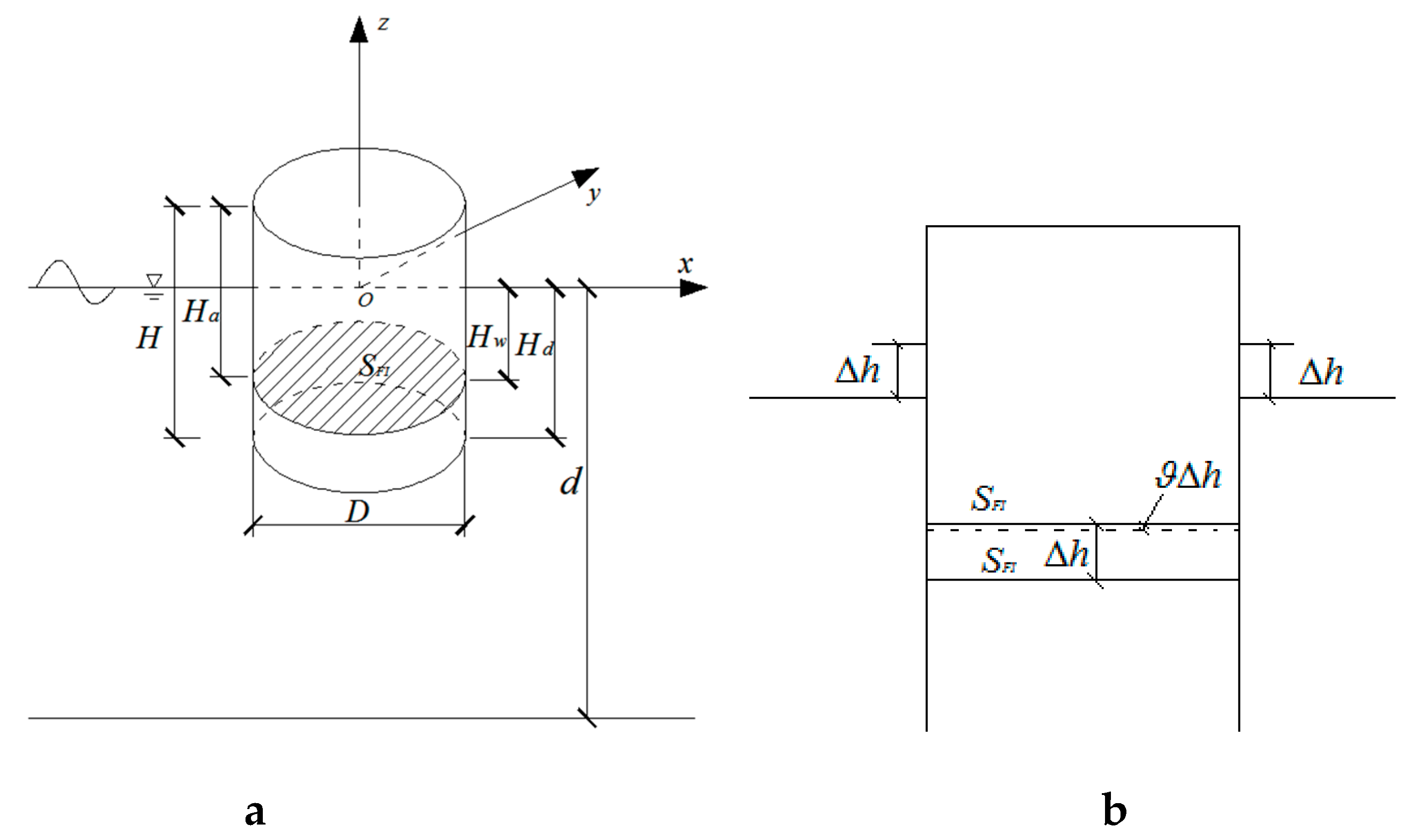
2.1. Theory of Air-Floating Mechanism for Single-Bucket Foundation

In the absence of external forces such as wave loads and current loads, the bucket foundation is balanced by gravity and buoyancy when floating on the water surface. As shown in Figure 3, for the i-th bucket foundation in LDMBF, the local coordinate system o x y z is used (for the convenience of analysis, i is omitted). The origin of the coordinate is located at the center of the top of the bucket, the positive directions of o x axis and o z axis are right and upward, respectively. The o y axis is determined by using the corkscrew rule. The diameter of the bucket foundation is D . Since the bucket foundation is a thin-walled structure, the effect of the thickness on the characteristics of the bucket foundation can be neglected. The cross-sectional area of the foundation is A , the height is H , the draft is H d , the height of the freeboard is H f , and the structural mass is M s . The difference of water head between the external and interior water surface S F I is H w and the height of the air column in the bucket is H a . The atmospheric pressure outside the bucket is P a . d is the water depth. The weight G s and the pressure P b at S F I are given by:
G s = M s g
P b = ρ w g H w + P a
F b = ρ w g H w A
where, ρ w is the density of water, g is the acceleration due to gravity and F b is buoyancy with the coordinates of the floating center at ( 0 , 0 , H w / 2 ) .
When the i-th bucket foundation is in equilibrium, G s and F b are equal in magnitude, opposite in direction and the action points are in the same line.
Due to the external force or structural vibration, As is shown in Figure 3b, when the foundation moves Δ h vertically downward, the height of the air column inside the bucket moves upward relative to the movement of the structure for a distance ϑ Δ h , where ϑ is a dimensionless parameter (see Appendix A) related to air compressibility. According to the Boyle-Mariotte’s law, the volume change in the air-cushion below the structure is reversible and can be described by the isothermal process, as follows:
P 0 V 0 = P 1 V 1
where P 0 and V 0 are the initial air pressure and the initial volume of air cushion, respectively; P 1 = P 0 + Δ P and V 1 = V 0 + Δ V are the air pressure and the volume after the movement of the structure, respectively. The resulting pressure inside the air cushion can be expressed as:
P 1 = P 0 V 0 V 1
The non-linear expression of the pressure in equation (4) can be simplified to a linear form by making use of the Taylor expansion for Δ V = 0 . After the simplification, the linear expression for the pressure is:
P 1 = P 0 P 0 Δ V V 0
The initial air pressure and the initial volume are P 0 = P b and V 0 = A H a , respectively. According to the definition of stiffness, which is the force required to cause a unit displacement, the stiffness of an air column can be expressed as:
C a = P b A H a
The air pressure and the volume after the movement Δ h of the structure are P 1 = P b + ρ w g ( 1 ϑ ) Δ h and
, respectively. Substitution Equation (5) into Equation (3) and making use of the changed air pressure and volume, the following expression can be obtained:
P b A H a = [ P b + ρ w g ( 1 ϑ ) Δ h ] A ( H a ϑ Δ h )
If the right hand side of Equation (7) is rewritten by the Taylor expansion for Δ h = 0 , the compressibility factor of the air cushion, similar to the factor derived from Kessel [22], can be expressed as:
ϑ = ρ w g H a P b + ρ w g H a
The detailed derivation process of the above equations from Equation (5) to Equation (9) are shown in Equation (A3).

2.2. Equations of Oscillating Motion for Multi-Bucket Foundation

The global coordinate system of the structure is shown in Figure 4. The origin O is located at the bottom of the structure under the centroid position. The positive direction of the O X axis, perpendicular to the line connecting the center of gravity of 2# and 3# bucket foundations, is the direction of the incident wave. The positive directions of O Z axis are upward and the O Y axis is determined by using the corkscrew rule.

2.2.1. Equation of Heaving Motion

The equation for the heaving motion can be expressed as:
M b Z Z · · + N Z Z · + C Z Z · = F Z
where, M b Z is the mass for the heaving motion, including the mass of the structure, the mass of the water column inside the bucket and the added mass, N Z is the damping coefficient for the heaving motion, F Z is the heave force, Z is the vertical displacement which can be expressed as the change of height of the air column, and C Z is the heave restoring coefficient or spring coefficient.
If the structure moves Δ h in the vertical direction, the change in the volume of the air cushion is A ( 1 ϑ ) Δ h , the corresponding change in buoyancy is ρ w g A ( 1 ϑ ) Δ h . The spring coefficient for the heaving motion is:
C Z = i = 1 I F b i Z = i = 1 I ρ w g A i ( 1 ϑ ) Δ h = i = 1 I ρ w g A i P b i P b i + ρ w g H a i = i = 1 I C a i C w i C a i + C w i
where, C a i , C w i is the stiffness of the air cushion, water column of the i-th bucket, I is the number of buckets in LDMBF, C Z is the total series stiffness of the air-spring stiffness and the water-spring stiffness inside the bucket.
The total mass M b Z which includes the mass of the structure, the mass of the water column inside the buckets and the added mass, can be expressed as:
M b Z = μ Z i = 1 I ( M s i + M w i )
where, μ Z is the added mass coefficient of the heaving motion of LDMBF. From the earlier studies on ship dynamics, the recommended value for ship dynamics is 1.2 [18,19]. The application of the added mass coefficient to LDMBF must be verified by theory, experimental test results, or results from other methods.

2.2.2. Equation of Rocking Motion

The rocking motion of LDMBF is induced by the rocking moment generated by the external loads. Because the expressions of rocking motion in rolling and pitching directions are similar and space is limited, just taking the rolling motion of the structure as an example, the equation of motion can be expressed as:
I b m X θ X + N m X θ X + C m X θ X = F m X
where, I b m X is the mass moment of inertia for the rolling motion, N m X is the damping coefficient of the rolling motion, F m X is the moment for the rotation about the O X axis, θ X is the rolling angle, and C m X is rotational restoring coefficients about the O X axis. Taking the LDMBF as an example, if the structure is rotated by an angle of Δ θ X around the O X axis, the buoyancy change of each buoy causes a change in the restoring moment, C m X can be expressed as:
C m X = F b m X θ X = i = 1 I F b i ( y b i y c ) θ X
where, y b i is the y coordinate of the floating center of the i-th bucket foundation, y c is the y coordinate of the rolling center of the structure. If the tilting angle is small, ( y b i y c ) θ X = h . Equation (13) can then be simplified to the following expression:
C m X = i = 1 I F b i ( y b i y c ) 2 h = i = 1 I ρ w g A i ( 1 ϑ ) ( y b i y c ) 2
Similar to the heaving motion, I b m X includes the moment of inertia of the structure to the central axis of the roll, the moment of inertia of the water plug to the rolling center axis and the added moment of inertia, can be expressed as:
I b m X = μ m X i = 1 I ( I s m x i + I w m x i )
where, I s m x i , I w m x i is the moment of inertia of i-th bucket and water column inside the i-th bucket, respectively; μ m X is the added mass coefficient of the rolling motion for LDMBF. From the earlier studies on ship dynamics, the recommended value is 1.2 [18,19], which is based on the results of the model tests only.

2.3. Method of Determining the Added Mass Coefficient and Damping Ratio for Oscillating Motion in Still Water

The natural angular frequencies ω j for oscillating motion obtained by solving Equation (10) and Equation (13) are:
ω j = C j / M b j
Where, C j represents the generalized coefficient of restoring force, which are C Z for heaving motion, C m X ( C m Y ) for rolling (pitching) motion; M b j represents the generalized mass, which are M b Z for heaving motion, I b m X ( I b m Y ) for rolling (pitching) motion.
The damping vibration periods for oscillating motion can be expressed as:
T j d = 2 π / ω j 2 N j 2 4 M b j 2
where, N j represents the generalized damping coefficient, which are N Z for heaving motion, N m X ( N m Y ) for rolling (pitching) motion.
As shown in Figure 5, the amplitude Ai of oscillating motion decreases exponentially as the time t increases. The ratio of two successive amplitudes Ai and Ai+1 separated by a time interval equal to the damping period T j d is:
A i A i + 1 = e n t e n ( t + T d )
where, n represents damping ratio, is n = N j / ( 2 M b j ) . Take the natural logarithm on both sides of Equation (19), the logarithmic decrement ratio δ can be expressed as:
δ = ln A i A i + 1 = n T j d
Ai, Ai+1 and T d can be obtained from experimental and simulated data to determine the value of n . The natural angular frequencies ω j and the generalized damping coefficient N j , the added mass coefficients can be obtained by substituting n to Equation (18), substituting Equation (18) to Equation (17), respectively.

3. Experimental Designs and MOSES Simulations

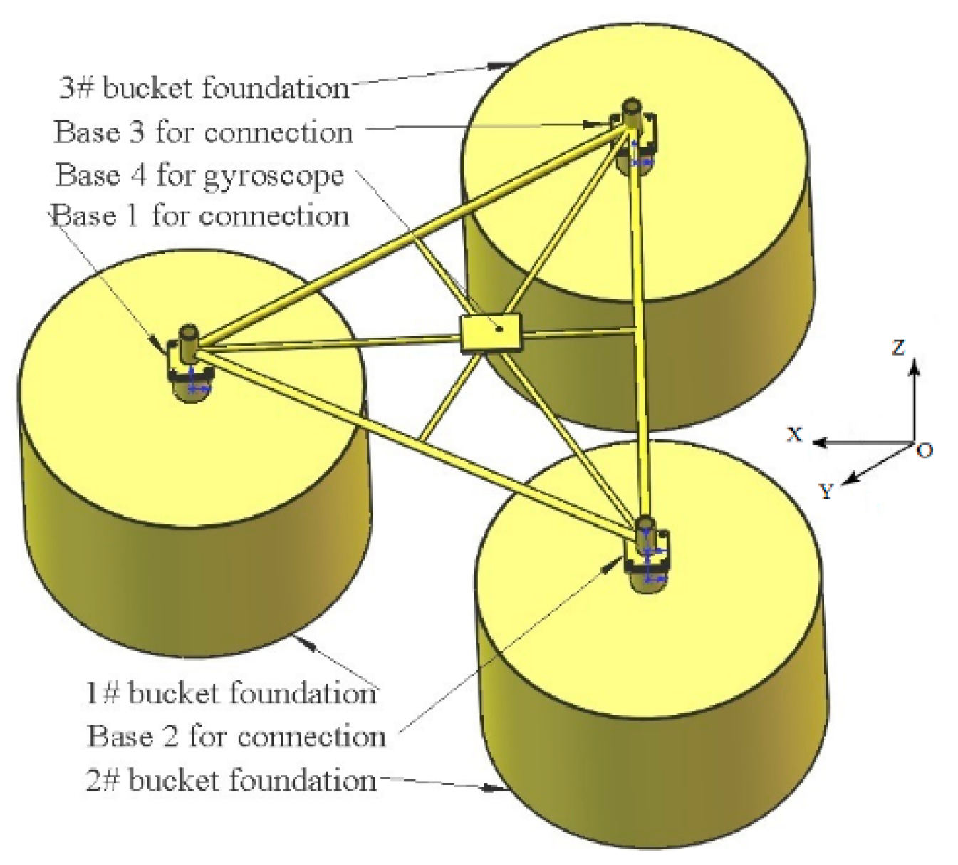
3.1. Physical and Experiment Models

As shown in Figure 6, the prototype structure of the multi-bucket foundation comprises of three bucket foundations numbered 1#, 2# and 3# and a connecting frame. The diameter and the height of the three bucket foundations are 10.0 m and 6.75 m, respectively (see Figure 6a). The center distance of the connecting frame is 15.0 m (see Figure 6b). There are three bases i.e., Base 1, Base 2 and Base 3 at each vertex of the frame to ensure a reliable connection with the corresponding bucket foundation. To prevent the sensor from contacting water during the oscillating process and to ensure the accuracy of the measured data, a steel tubular with the diameter of 1.0 m and the height of 1.25 m has been fixed at the top of each bucket foundation, which connects to the corresponding base of the frame. A vertical gyroscope is placed on Base 4 at the center of the connecting frame (see Figure 4).
As shown in Figure 7, a steel model of 1/25 scale of the LDMBF has been constructed according to geometric similarity and Froude number similarity. With the 2.0 mm thick side wall and 1.0 mm thick top lid, the diameter, height and mass of a single bucket foundation are 0.4 m, 0.25 m, and 5.85 kg, respectively. An exhaust valve has been installed on the lid of each bucket foundation which can be used to adjust the draft of the structure, and the calibration bar has been installed on the side wall of every bucket so as to ensure the accuracy of the adjustment. The center distance of the connecting frame model is 0.6 m and the weight is 1.2 kg.

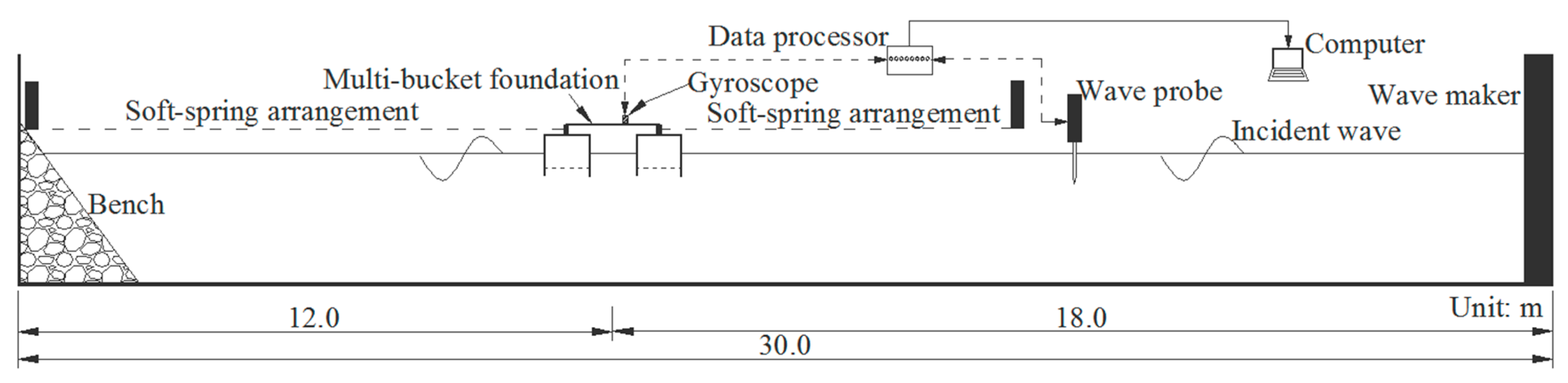
3.2. Experimental Setup

The experiments have been carried out in the harbor basin of the National Engineering Research Center for Inland Waterway Regulation of Chongqing Jiaotong University in China. The dimensions of the basin are 30 m in length, 20 m in width and 1.2 m in depth. Inside the basin, regular and irregular waves can be generated with a period of 0.5~5 s, wave height of 0.02~0.25 m and maximum water depth in the basin is 0.8 m. Figure 8 shows a sketch diagram of the experimental setup. All the tests were carried out with the head waves at zero forward speed. The LDMBF has been placed at a distance of 18.0 m from the wave-making machine, a wave-absorbing beach was located at the other end to reduce the wave reflection. The wave height is measured by the wave probe between the structure and wave maker. In order to limit the structure within a certain range of motion without affecting the wave-frequency motion, the model has been moored by a horizontally placed soft-spring arrangement at the bow and the stern [25,46,47].

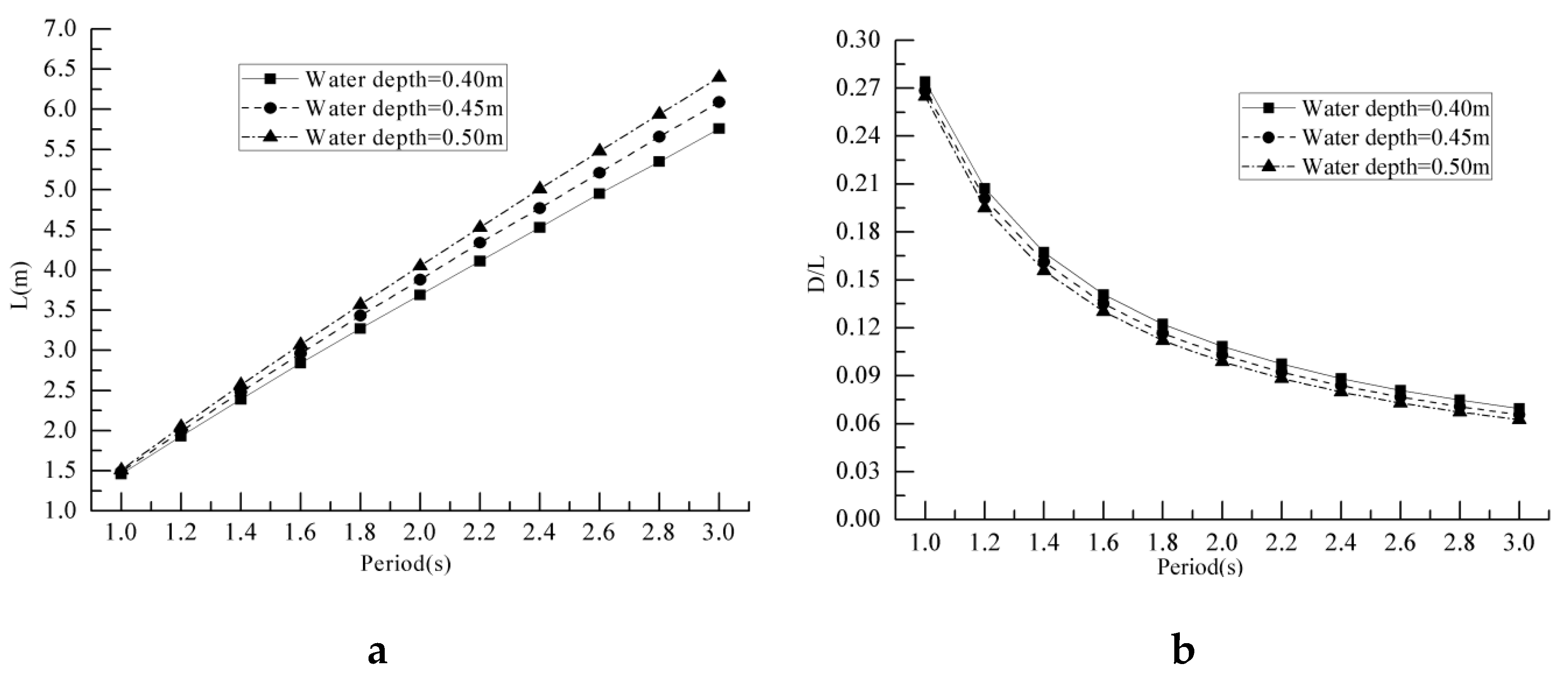
3.3. Tests in Regular Waves

The tests have been carried out in regular waves in order to investigate the characteristics of the amplitude–frequency response on the motion of heave and pitch. Since the target geometry scale factor in this study is 1/25, thus, the scale for wave height is also 1/25 and the scale for wave period is 1/5. The target wave height has been set fixed at 0.08 m, and the model wave period ranges from 1.0~3.0 s, while the prototype wave period is 5.0~15.0 s, which is within the range of most wave periods for wind-generated waves. Figure 9 shows all the wave conditions tested in the experiment. It can be seen that the wave length is mainly affected by the wave period and the water depth under the same wave height. In this study, three water depths: 0.40 m, 0.45 m and 0.50 m with 0.18 m draft and three drafts: 0.16 m, 0.18 m, 0.20 m with 0.5 m water depth have been examined.
Table 1 shows the pertinent parameters of the prototype and the physical model in the experiments. As shown in Table 1, MS is the mass of LDMBF, MW is the total mass of water column in all the bucket. The basic mass MS plus MW, the basic moment of inertia IsmX plus IwmX increase with increasing draught. The main reason is that the mass of the water column inside the bucket increase with the increasing of the draught.

3.4. MOSES Numerical Simulation

Using MOSES, the numerical models of prototype in still water and in wave have been developed to predict the dynamic behaviors of free oscillating motions and movements in waves, as shown in Figure 10.
There are three hydrodynamic theories (i.e., Morison’s equation, three dimensional diffraction, and two dimension diffraction) which can be chosen to computer the hydrodynamic performances. From Figure 8, it can been seen that the ratios of the characteristic length to the wavelength (D/L) ranges from 0.06 to 0.28. In order to improve the efficiency and accuracy of the numerical computations, the models used in the calculations are all based on the theory of three-dimensional diffraction. In MOSES, the key commands have been set for the air-floating LDMBF study are as follows: the option ‘–OPEN_VALVE’ and in command ‘&COMPARTMENT’ so as to specify that all the flood valves attached to the compartment are open. The ambient water flows into the compartment, or the contents flow out depending on the location of the valves, internal pressure, and amount of ballast in the compartment. The initial water filling in the compartment and the initial air pressure with different drafts have been set by the options ‘-PERCENT’and ‘-INT_PRE’ [48] (MOSES, 2009). The pertinent parameters for the numerical simulations under different draft conditions are shown in Table 2.

4. Results and Discussion

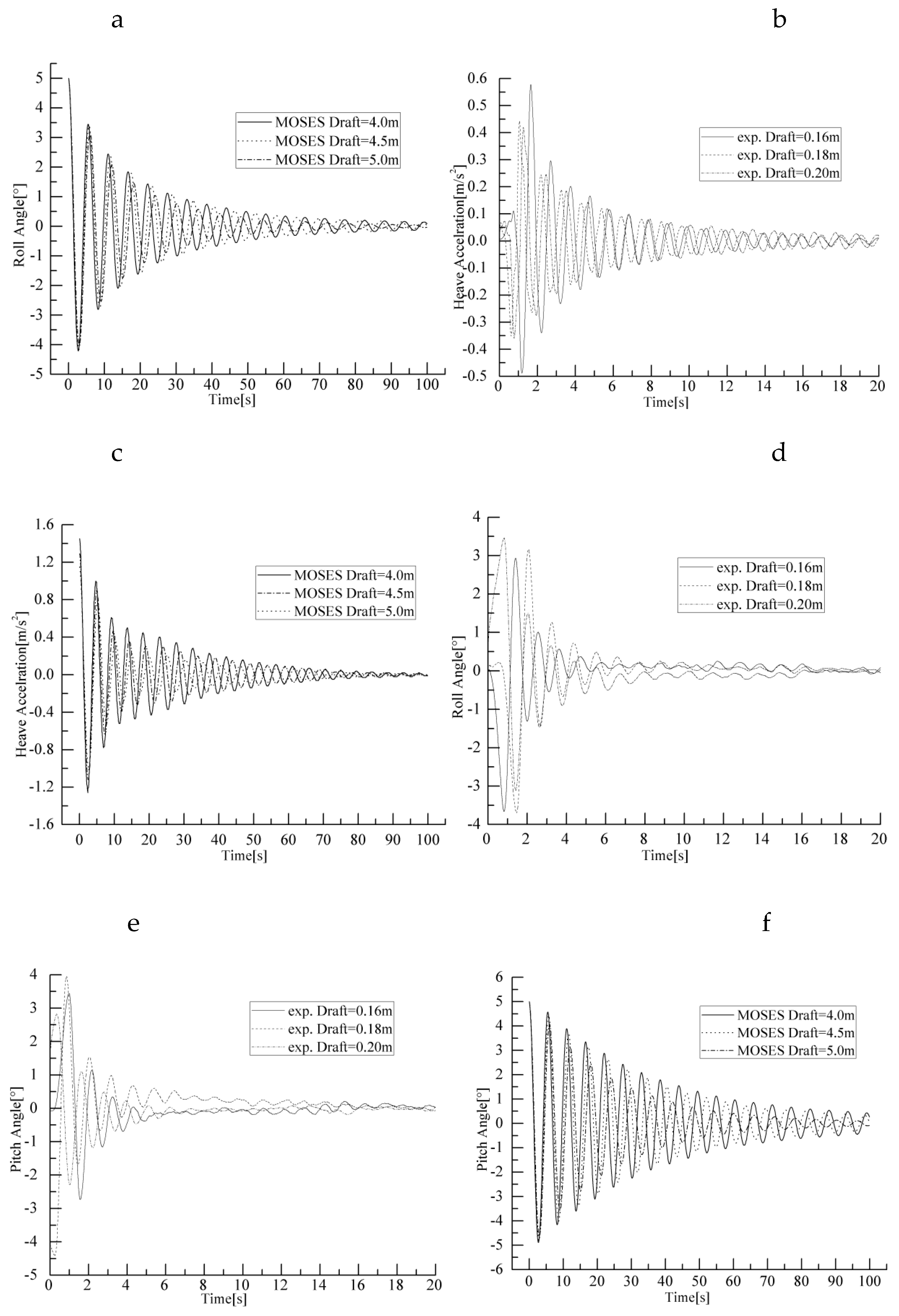
4.1. Free-Decay Tests

The natural frequencies and damping ratios of the LDMBF in heave, roll and pitch have been determined by free-oscillation experiments. In fact, during the air-floating process, the structure oscillates freely when a disturbance is applied to the body. The heaving and rocking motion are often simultaneous and coupled, but within a period of time after the interference force is removed from the structure. The form of the free motion is mainly manifested by the type of disturbance force applied. If the interference force is a vertical force at the center of gravity of the structure and a couple consists of horizontal forces, the main form of free motion is the heaving motion and the rocking motion. By giving the initial displacements of 5 cm, 5° and 5° in the direction of heave, roll and pitch respectively, the model tests has been taken with different drafts. In order to ensure the accuracy and validity of the experimental data, three tests have been carried out for the same draft in every direction. The attenuation curves of the heave acceleration and rocking angles have been obtained by gyroscope. The sampling frequency is 200 Hz. The damping vibration period Td, damping ratios n of the structure can be determined from these signatures by the logarithmic decrement method [46,47].
Due to the scale effect, the results of the model tests and the MOSES simulations are influenced by size and various environmental factors. However, they can reflect the hydrodynamic performances of the prototype structure. From Section 3.1, the similarity scale for models to the prototypes of LDMBF is based on geometric similarity and gravity similarity. The similarity ratio of translational accelerations in surge, sway, and heave motions and the rotational angles in roll, pitch, and yaw motions are all 1/1. The MOSES prototype model of LDMBF has been developed to simulate and analyze the air-floating characteristics. Figure 11 shows the experimental and simulated attenuation curves of heave acceleration, roll angle, and pitch angle for drafts of three different sizes. Using the logarithmic decrement method and Equations (9) and (12), the parameters used to calculate the added mass coefficients and damping ratios for the movements of heave, roll and pitch are shown in Table 3. Comparing Figure 11a and Figure 11b, Figure 11c and Figure 11d, Figure 11e and Figure 11f, it can be seen that the rates of attenuation of the experimental curves are faster than those of the simulated curves, which is an indication that the damping in the model tests is larger than that in the simulations. This is because the method used by MOSES for time-domain analysis is the Newmark method. The default values for the two parameters, γ and β , are 0.25 and 0.5, respectively. Using these values in the simulations, there is almost no numerical damping. In fact, for some simulations, there is a small negative damping. If the default values are changed to 0.33 and 0.66 respectively, then there is a small numerical damping. Normally, whether there is numerical damping is not a concern, except for simulating attenuation curves in calm seas, and then the default values do not work very well. Nevertheless, from Table 3 and Table 4, it can be seen that damping vibration periods for heave, roll and pitch, the experimental periods are in good agreement with the simulated periods, and the maximum relative error is only 1.60%.
From the experimental results in Table 3, it can be seen that with larger draft, the damping vibration periods for the motions of heaving and rocking are longer. However, with larger draft, the added masses for heaving and rocking are smaller. These results contradict the results in the earlier study [20]. The reason is that the basic mass used to calculate the added mass coefficient in the earlier study is only the structural mass, but in this study, both the structural mass and the mass of water plug inside every bucket foundation have been used in the calculations. Taking the heaving motion with drafts of three different sizes, the added mass coefficients are 4.48, 4.67 and 4.97 by not considering the mass of water plug. Hence, the coefficient is bigger for larger draft. The added mass coefficients obtained from the model tests in oscillatory motions are all greater than 1.2. The larger the draft, the closer it gets to the recommended value of 1.2 from the ship dynamics. The reason is that the stiffness of the air-spring is larger for larger draft, therefore, the stiffness of the series springs comprising air-spring and water-spring becomes more closer to the stiffness of the water-spring. The corresponding movement of the structure becomes closer to the movement of a rigid body. The experimental results show that the damping ratio of heaving motion is smaller than that of rocking motion. With the drafts of three different sizes, the damping ratio of the heaving motion ranges from 0.051 to 0.064, the damping ratio of the roll motion ranges from 0.081 to 0.066, and the damping ratio of the pitch motion ranges from 0.095 to 0.074.

4.2. Motion Responses in Waves

From Section 3.1, the similarity scale for models to the prototypes of LDMBF is based on geometric similarity and gravity similarity. The similarity ratio of translational accelerations in surge, sway, and heave motions and the rotational angles in roll, pitch, and yaw motions are all 1/1. For comparison with MOSES results, all the graphs for RAOs are shown in prototype scale.

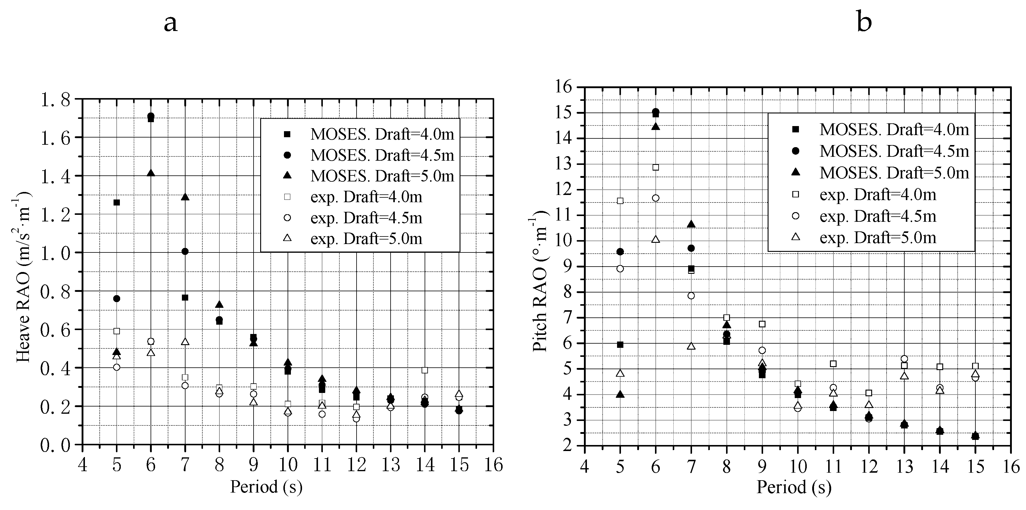
4.2.1. Effects of Draft Heights

The draft height is a dominating factor governing the motion of the LDMBF. With a small draft, the height of the water plug inside the bucket is relatively small, easily giving rise to air leakage or even overturning during transportation. With a large draft, the distance between the structure and seabed becomes closer, which increases the risk of structure grounding. The response in the air-floating towing process can then be larger due to the appearance of serious trim by head. Therefore, an appropriate draft is a key step in ensuring feasible design and safe construction. Figure 12 shows comparisons of the experimental and simulated response amplitude operators (RAOs) for drafts of three different sizes with a water depth of 12.5 m. It can be seen that both the experimental and simulated maximum amplitudes for the movements of the heave and pitch all occur near natural periods. The results of model tests show that the draft size has a large effect on the heave and pitch movements, while the simulation results show that draft size has a larger effect on the direction of the heave than the direction of the pitch.
Figure 12a shows that within the period of 5~13 s, the simulated heaving motions are far larger than the experimental heaving motion. From the experimental data, the maximum amplitudes of heave acceleration 0.59 m/s2 at 4.0 m draft, 0.54 m/s2 at 4.5 m draft, and 0.53 m/s2 at 5.0 m draft occurred near the periods of 5 s, 6 s, and 7 s, respectively, i.e., the resonant periods of heaving motion increase with increasing draft, while the motion responses decrease with the increasing draft. That is because the natural period and the stiffness of the heaving motion become longer and stiffer with larger draft. When the period is longer than 7 s, the amplitudes of heave acceleration first decreased and then increased slightly with increasing draft. The larger the wave period, the more significant the trend. The heave acceleration at 4.5 m draft is almost smaller in most periods.
Figure 12b shows that the simulated movements of the pitch are in good agreement with the experimental movements, both in magnitude and in trend. The period of the maximum amplitude is about 6 s. From the model tests, the maximum amplitudes of pitch angle appearing near 6 s were 12.9 at 4.0 m draft, 11.7° at 4.5 m draft, and 10.0 at 5.0 m draft. Unlike the heaving motion, for drafts of different heights, the change in the simulated amplitudes of the pitch motion is smaller than that of the experimental amplitudes. For a period longer than 8 s, the experimental results are larger than those of simulated results. Similar to the heaving motion, for larger draft, the amplitude of the pitch motion is smaller. Therefore, under the premise of stability and seakeeping, the wave-induced motion can be reduced significantly by using a larger draft of an appropriate size for the LDMBF.

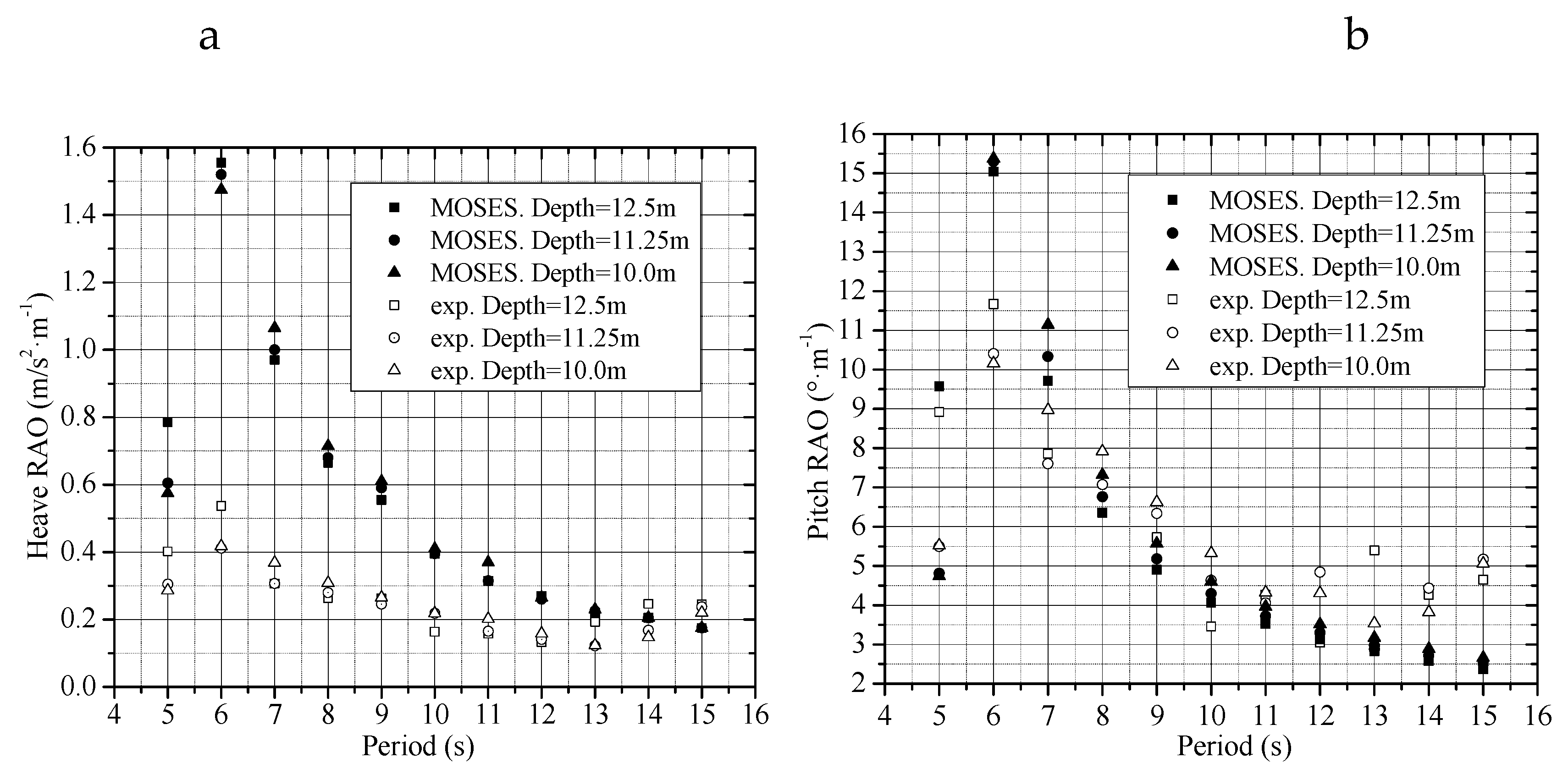
4.2.2. Effects of Water Depth

In addition to draft size, the change in the water depth during construction is also one of the critical factors affecting the safety of LDMBF. For conventional ship, the water depth has a significant impact on the longitudinal movement and wave-induced loads of the ship. With decreasing water depth, the peak responses in the directions of heave and pitch tend to be smaller, while the bending moment and the shear force become larger. The faster the speed of the ship, the impact on the responses of the ship is more significant [49].
Figure 13 shows the comparisons of the experimental and simulated RAOs for the different water depths with a draft of 4.5 m. Similar to the effect of the draft size on the LDMBF, the largest amplitudes of the experimental and simulated heave accelerations and pitch angles all occur near the natural periods. For a wave period shorter than the natural period, the responses of the heave and pitch motions increase with increasing water depth. By contrast, for the wave period longer than the natural period, the responses decrease.
From Figure 13a, it can be seen that within the period between 5–14 s, the simulated heaving movements are much larger than the experimental movements. Further, both the experimental and simulated amplitudes decrease with decreasing water depth. As the water depth changes from 12.5 m to 11.25 m, the changes in the largest simulated and experimental amplitudes are 0.0059 m/s2 and 0.045 m/s2, respectively. Furthermore, as the water depth changes from 11.25 m to 10.0 m, the changes in the largest simulated and experimental amplitudes are 0.125 m/s2 and 0.035 m/s2 respectively. The amplitude increases with increasing water depth.
Figure 13b shows that the simulated movement of pitch is in good agreement with the experimental movement, both in magnitude or in trend. As the water depth changes from 12.5 m to 11.25 m, the changes in the largest simulated and experimental amplitudes are 2.43% and 0.53%, respectively. Furthermore, as the water depth changes from 11.25 m to 10.0 m, the changes in the largest simulated and experimental amplitudes are 7.37% and 1.67%, respectively. For the period longer than 8 s, the experimental results are larger than those of simulated results. Similar to the heaving motion, the change in the amplitude of the pitching movement decreases with increasing water depth.

5. Conclusions

In this study, the heaving and rocking equations of motion of air-floating LDMBF were derived by the theory of single DOF damped vibration. The ideal air state equation has been used to consider the compression effect of the air cushion inside the bucket and the oscillation equations of the LDMBF have been developed. Combined with the 1/25 scale physical model tests and the numerically simulated prototype models by the hydrodynamic software MOSES, the natural periods, added mass coefficients and damping characteristics of the LDMBF in free oscillations and the response amplitude operator (RAO) have been investigated. In this context, the main conclusions of the study are as follows:
The compressibility factor ϑ describes the difference in the generalized stiffness (stiffness of heaving motion and restoring coefficient of rocking motion) between the LDMBF and the conventional rigid-bottom float.
The natural periods of heaving, rolling and pitching motion tend to increase with increasing draft.
The added mass coefficient, which varies between 1.2 and 1.6, is equal to or larger than the recommended coefficient for ship dynamics. The coefficient 1.2 can be taken as the lower limit for a large draft and 1.6 can be taken as the upper limit for a small draft. The most possible reason is that the stiffness of the air-spring is larger for larger draft; the stiffness of the series springs comprising air-spring and water-spring becomes closer to the stiffness of the water-spring and the corresponding movement of the structure becomes closer to the movement of a rigid body.
The simulated pitching movements of the LDMBF by MOSES are in good agreement with the corresponding experimental results both in tendency and in magnitude. The simulated heaving movement by MOSES can be used to forecast the trend of the motion. However, there are quantitative differences between the simulated and the model test results.
In the model tests, the resonant periods of heaving motion increase with increasing draft while the maximum motion responses decrease with the increasing draft.
In the model tests, the amplitudes of pitching angle decrease with increasing draft and have an especially significant trend when the period is less than 9 s.
The resonant period for heave motion decreased from 6 s to 5 s with a shallower water depth. This can be attributed to the added draft resulting from the blocking effect of ocean fluid.
The amplitudes of heaving acceleration and pitching angle decrease to a limited extent with decreasing water depth. Earlier studies have shown that the effect of water depth is more significant if the speed of the structure is increased [49]. Hence, further studies will be carried out to investigate the effect of towing speed.

Author Contributions

Conceptualization, H.D., M.Z., P.Z. and X.L.; Methodology, H.D., P.Z. and X.L.; Software: X.L., C.L.; Validation, P.Z. and X.L.; Formal analysis, X.L. and C.L.; Investigation, D.H., M.Z., P.Z. and X.L.; Resources: H.D., M.Z. and P.Z.; Data Curation, X.L. and C.L.; Writing-Original Draft Preparation, X.L., P.Z. and C.L.; Writing-Review & Editing. X.L., P.Z. and C.L.; Supevision, H.D., M.Z.; Project Administration, H.D., P.Z. and X.L.; Funding acquisition: H.D., P.Z. and X.L.

Funding

The author would like to acknowledge the support by the National Natural Science Foundation of China (Grant No. 51679163), Chongqing Municipal Natural Science Foundation (Grant No. CSTC2016JCYJA0580), and State Key Laboratory of Hydraulic Engineering Simulation and Safety (Tianjin University) (Grant No. HESS-12).

Conflicts of Interest

The authors declare no conflict of interest.

Appendix A

1. Notation
DOFdegree of freedom
LDMBFlarge-diameter multi-bucket foundation
RAOresponse amplitude operator
OWToffshore wind turbine
SBJsuction-bucket jacket
CBFcomposite-bucket foundation
CGSconcrete gravity structure
LPCBFlarge prestressed concrete bucket foundation
2. Abbreviations
Ddiameter of the bucket
Across-sectional area of the bucket
Hheight of the i-th bucket foundation
Hddraft of the i-th bucket foundation
Hffreeboard of the i-th bucket foundation
Hwdifference of water head between the external and interior water surface
Paatmospheric pressure
Pbpressure in the bucket
Gsweight of the bucket
msmass of the i-th bucket
mwmass of the water column inside the i-th bucket
Mstotal mass of the structure
Mwtotal mass of the water column inside the structure
MbZtotal mass for the heaving motion
x, y, zlocal cartesian coordinate system
X, Y, Zglobal cartesian coordinate system
z ˙ velocity for the heaving motion
z ¨ acceleration for the heaving motion
Nzdamping coefficient for the heaving motion
Castiffness of the air cushion in i-th bucket
Cwstiffness of the water column in i-th bucket
CZtotal series stiffness of structure
FZforce in the heaving direction
ϑ dimensionless parameter related to air compressibility
Δ h movement distance in the heaving direction
Δ V volume variation of the air cushion
P0initial air pressure in the bucket
V0initial air volume in the bucket
P1air pressure after the movement Δ h
V1air volume after the movement Δ h
IbmXtotal rolling inertia moment
IbmYtotal pitching inertia moment
Ismxrolling inertia moment of the structure
Ismypitching inertia moment of the structure
IwmXtotal rolling inertia moment of the water plug in the bucket
IwmYtotal pitching inertia moment of the water plug in the bucket
NmXtotal damping coefficient of the rolling motion
NmYtotal damping coefficient of the pitching motion
θ X rolling angle
θ X rolling angular velocity
θ X rolling angular acceleration
Fbbuoyancy
Fmxmoment in the rolling motion
Fbmxrolling moment of buoyancy
Cmxrolling restoring coefficient
FmXtotal moment in the rolling motion
FbmXtotal rolling moment of buoyancy
CmXtotal rolling restoring coefficient
ycy coordinate of rocking center of the structure
yby coordinate of floating center of the structure
μ Z heaving added mass coefficient of the structure
μ m X rolling added mass coefficient of the structure
μ m Y pitch added mass coefficient of the structure
ggravitational acceleration
nZdamping ratio of heaving motion
nmXdamping ratio of rolling motion
nmYdamping ratio of pitching motion
3. Dimensionless Parameter ϑ
Based on Equation (4), where P 0 and V 0 are the initial air pressure and the initial volume of the air cushion, respectively; P 1 and V 1 are the air pressure and the volume after the movement of the structure, respectively. The resulting pressure inside the air cushion can be expressed as:
P 1 = P 0 V 0 V 1 = P 0 V 0 V 0 + Δ V
where, Δ V is the volume change after the movement of the structure.
f ( Δ V ) = P 0 V 0 V 0 + Δ V
It follows that:
f ( Δ V ) = P 0 V 0 1 ( V 0 + Δ V ) 2
The non-linear expression of the pressure in Equation (5) can be simplified to a linear form by making use of the Taylor expansion for Δ V = 0 :
P 1 = f ( Δ V ) | Δ V = 0 + f ( Δ V ) | Δ V = 0 Δ V = P 0 V 0 V 0 + P 0 V 0 1 V 0 2 Δ V = P 0 P 0 Δ V V 0
Δ P = P 1 P 0 = P 0 Δ V V 0
According to the definition of stiffness, which is the force required to cause a unit displacement. The initial air pressure and the initial volume are P 0 = P b and V 0 = A H a , respectively. The stiffness of an air column can be expressed as:
C a = Δ P A Δ V = P b A H a
where, Δ P is the pressure change after the movement of the structure. The air pressure and the volume after the movement Δ h of the structure are P 1 = P b + ρ w g ( 1 ϑ ) Δ h and V 1 = A ( H a ϑ Δ h ) , respectively. Substituting Equation (A4) into Equation (4) and making use of the changed air pressure and volume, the following expression can be obtained:
P b A H a = [ P b + ρ w g ( 1 ϑ ) Δ h ] A ( H a ϑ Δ h )
If:
g ( Δ h ) = [ P b + ρ w g ( 1 ϑ ) Δ h ] A ( H a ϑ Δ h )
It follows that:
g ( Δ h ) = ρ w g A ( 1 ϑ ) ( H a ϑ Δ h ) ϑ A [ P b + ρ w g ( 1 ϑ ) Δ h ]
A Taylor expansion of g ( Δ h ) around Δ h = 0 provides:
g ( Δ h ) = g ( Δ h ) | Δ h = 0 + g ( Δ h ) | Δ h = 0 Δ h = P b A H a + [ ρ w g A ( 1 ϑ ) H a - P b A ϑ ] Δ h
Substitution Equation (A10) into Equation (A7) yields:
P b A H a = P b A H a + [ ρ w g A ( 1 ϑ ) H a - P b A ϑ ] Δ h
Resulting in the compressibility factor:
ϑ = ρ w g H a P b + ρ w g H a

References

  1. Snyder, B.; Kaiser, M.J. Ecological and economic cost-benefit analysis of offshore wind energy. Renew. Energy 2009, 34, 1567–1578. [Google Scholar] [CrossRef]
  2. Blanco, M.I. The economics of wind energy. Renew. Sustain. Energy Rev. 2009, 13, 1372–1382. [Google Scholar] [CrossRef]
  3. Wang, T. Global Offshore Wind Power Market-Statistics & Facts. 2019. Available online: https://www.statista.com/topics/2764/offshore-wind-energy/ (accessed on 15 July 2019).
  4. Byrne, B.W.; Houlsby, G.T.; Martin, C.; Fish, P. Suction caisson foundations for offshore wind turbines. Wind Eng. 2002, 26, 145–155. [Google Scholar] [CrossRef]
  5. Ding, H.; Liu, Y.; Zhang, P.; Le, C. Model tests on the bearing capacity of wide-shallow composite bucket foundations for offshore wind turbines in clay. Ocean Eng. 2015, 103, 114–122. [Google Scholar] [CrossRef]
  6. Houlsby, G.T.; Ibsen, L.B.; Byrne, B.W. Suction caissons for wind turbines. In Proceedings of the First International Symposium on Frontiers in Offshore Geotechnics, University of Western Australia, Perth, WA, Australia, 19–21 September 2005; pp. 75–93. [Google Scholar]
  7. Lars, B.I. The bucket foundation and its competitiveness versus monopiles and jacket structures. In Proceedings of the International Conference in Research at Alpha Ventus, Bremerhaven, Germany, 9–10 May 2012. [Google Scholar]
  8. Zhang, P.Y.; Han, Y.Q.; Ding, H.Y.; Zhang, S.Y. Field experiments on wet tows of an integrated transportation and installation vessel with two bucket foundations for offshore wind turbines. Ocean Eng. 2015, 108, 769–777. [Google Scholar] [CrossRef]
  9. Fu, D.F.; Bienen, B.; Gaudin, C.; Cassidy, M. Undrained capacity of a hybrid subsea skirted mat with caissons under combined loading. Canadian Geotech. J. 2014, 51, 934–949. [Google Scholar]
  10. Bie, S.A.; Ji, C.N.; Ren, Z.J.; Li, Z.Z. Study on floating properties and stability of air floated structures. China Ocean Eng. 2002, 16, 263–272. [Google Scholar]
  11. Ding, H.; Hu, R.; Le, C.; Zhang, P. Towing Operation Methods of Offshore Integrated Meteorological Mast for Offshore Wind Farms. J. Mar. Sci. Eng. 2019, 7, 100. [Google Scholar] [CrossRef]
  12. Faltinsen, O.M. Sea Loads on Ships and Offshore Structures; Cambridge University Press: London, UK, 1990. [Google Scholar]
  13. Qi, X.Y. Experimental Study on Behaviour of an Open Bottom Floating Platform in Wave, Wind and Current. In Proceedings of the International Offshore and Polar Engineering Conference, Osaka, Japan, 10–15 April 1994. [Google Scholar]
  14. Thiagarajan, K.P.; Morison-Thomas, M.T. Wave-induced motions of an air cushion structure in shallow water. Ocean Eng. 2006, 33, 1143–1160. [Google Scholar] [CrossRef]
  15. Thiagarajan, K.P.; Morris-Thomas, M.T.; Spargo, A. Heave and pitch response of an offshore platform with air cushion support in shallow water. In Proceedings of the 23rd International Conference Offshore Mechanic and Arctic Engineering, Vancouver, BC, Canada, 20–25 June 2004; pp. 1–7. [Google Scholar]
  16. Zhang, P.Y.; Ding, H.Y.; Le, C.H.; Huang, X. Motion analysis on integrated transportation technique for offshore wind turbines. J. Renew. Sustain. Energy 2013, 5, 053117. [Google Scholar] [CrossRef]
  17. Seidl, L.H. Development of an Air Stabilized Platform; University of Hawaii, Department of Ocean Engineering technical report submitted to US Department of Commerce, Maritime Administration; University of Hawaii: Honolulu, HI, USA, 1988. [Google Scholar]
  18. Bhattacharyya, R. Dynamics of Marine Vehicles; China Ocean Press: Beijing, China, 1982. [Google Scholar]
  19. James, F.J.; Wilson, J.F. Dynamics of Offshore Structures; A Wiley-Inter Science Publication: New York, NY, USA, 1984. [Google Scholar]
  20. Chenu, B.; Morris-Thomas, M.T.; Thiagarajan, K.P. Some hydrodynamic characteristics of an air-cushion supported concrete gravity structure. In Proceedings of the 15th Australasian Fluid Mechanics Conference, Sydney, Australia, 13–17 December 2004. [Google Scholar]
  21. Thiagarajan, K.P. Hydrostatic stability of compartmented structures supported by air cushions. J. Ship Res. 2009, 53, 151–158. [Google Scholar]
  22. Van Kessel, J.L.F. Aircushion Supported Mega-Floaters. Ph.D. Thesis, Delft University of Technology, Delft, The Netherlands, 2010. [Google Scholar]
  23. Pinkster, J.A.; Fauzi, A. Motions and drift forces of air-supported structures in waves. In Proceedings of the Fifth Workshop on Nonlinear Wave Action on Structures and Ships, La Garde, France, 4 September 1998. [Google Scholar]
  24. Pinkster, J.A.; Fauzi, A.; Inoue, Y.; Tabeta, S. The behavior of large air cushion supported structures in waves. In Proceedings of the second International Conference on Hydroelasticity in Marine Technology, Fukuoka, Japan, 1–3 December 1998; pp. 497–506. [Google Scholar]
  25. Pinkster, J.A.; Meevers Scholte, E.J.A. The behavior of a large air-supported MOB at sea. Mar. Struct. 2001, 14, 163–179. [Google Scholar] [CrossRef]
  26. Tabeta, S. Model Experiments on Barge Type Floating Structures Supported by Air Cushions; Ship Hydromechanics Laboratory Report; Delft University of Technology: Delft, The Netherlands, 1998; p. 1125. [Google Scholar]
  27. Malenica, S.; Zalar, M. An alternative method for linear hydrodynamics of air cushion supported floating bodies. In Proceedings of the Fifth International Workshop on Water Waves and Floating Bodies, Caesarea, Israel, 17 February–1 March 2000; pp. 1–4. [Google Scholar]
  28. Guéret, R.; Hermans, A.J. Air cushion under floating offshore structure. In Proceedings of the Sixth International Workshop on Water Waves and Floating Bodies, Hiroshima, Japan, 22–25 April 2001; pp. 45–49. [Google Scholar]
  29. Kessel Van, J.L.F.; Pinkster, J.A. The effect of aircushion division on the structural loads of large floating offshore structures. In Proceedings of the ASME 2007 26th International Conference on Offshore Mechanics and Arctic Engineering, San Diego, CA, USA, 10–15 June 2007; American Society of Mechanical Engineers: New York, NY, USA, 2007. [Google Scholar]
  30. Van Kessel, J.L.F.; Pinkster, J.A. Wave-induced structural loads on different types of aircushion supported structures. In Proceedings of the Seventeenth International Offshore and Polar Engineering Conference, Lisbon, Portugal, 1–6 July 2007. [Google Scholar]
  31. Le, C.H.; Ding, H.Y.; Zhang, P.Y. Air-floating towing behaviors of multi-bucket foundation platform. China Ocean Eng. 2013, 27, 645–658. [Google Scholar] [CrossRef]
  32. Achmus, M.; Kuo, Y.S.; Abdel-Rahman, K. Behavior of monopile foundations under cyclic lateral load. Comput. Geotech. 2009, 36, 725–735. [Google Scholar] [CrossRef]
  33. Banerjee, A.; Chakraborty, T.; Matsagar, V. Evaluation of possibilities in geothermal energy extraction from oceanic crust using offshore wind turbine monopiles. Renew. Sustain. Energy Rev. 2018, 92, 685–700. [Google Scholar] [CrossRef]
  34. Banerjee, A.; Chakraborty, T.; Matsagar, V. Stochastic Dynamic Analysis of an Offshore Wind Turbine Considering Frequency-Dependent Soil–Structure Interaction Parameters. Int. J. Struct. Stab. Dyn. 2018, 18, 1850086. [Google Scholar] [CrossRef]
  35. Banerjee, A.; Chakraborty, T.; Matsagar, V.; Achmus, M. Dynamic analysis of an offshore wind turbine under random wind and wave excitation with soil-structure interaction and blade tower coupling. Soil Dyn. Earthq. Eng. 2019, 125, 105699. [Google Scholar] [CrossRef]
  36. Banerjee, A.; Chakraborty, T.; Matsagar, V. Dynamic analysis of an offshore monopile foundation used as heat exchanger for energy extraction. Renew. Energy 2019, 131, 518–548. [Google Scholar] [CrossRef]
  37. Le, C.H.; Kim, S.R. Evaluation of combined horizontal moment bearing capacities of tripod bucket foundations in undrained clay. Ocean Eng. 2014, 85, 100–109. [Google Scholar]
  38. Kinsman, B. Wind Waves: Their Generation and Propagation of the Ocean Surface; Dover Publications: New York, NY, USA, 1965. [Google Scholar]
  39. Andersen, L.V. Dynamic soil–structure interaction of polypod foundations. J. Comp. Struc. 2018, 7, 007. [Google Scholar] [CrossRef]
  40. Andersen, L.; Andersen, T.; Manuel, L. Model uncertainties for soil-structure interaction in Offshore Wind Turbine monopile foundations. J. Mar. Sci. Eng. 2018, 6, 87. [Google Scholar] [CrossRef]
  41. Peplow, A.T.; Andersen, L.V.; Bucinskas, P. Environmental vibration reduction utilizing an array of mass scatterers. Procedia Eng. 2017, 199, 1368–1373. [Google Scholar] [CrossRef]
  42. Bayat, M.; Andersen, L.V.; Ibsen, L.B. P-y-ẏ curves for dynamic analysis of offshore wind turbine monopile foundations. Soil Dyn. Earthq. Eng. 2016, 90, 38–51. [Google Scholar] [CrossRef]
  43. Bayat, M.; Andersen, L.V.; Ibsen, L.B.; Clausen, J. Influence of pore water in the seabed on dynamic response of offshore wind turbines on monopiles. Soil Dyn. Earthq. Eng. 2017, 100, 233–248. [Google Scholar] [CrossRef]
  44. Elias, S.; Matsagar, V.; Datta, T.K. Distributed multiple tuned mass dampers for wind response control of chimney with flexible foundation. Procedia Eng. 2017, 199, 1641–1646. [Google Scholar] [CrossRef]
  45. Elias, S.; Matsagar, V.; Datta, T.K. Along-wind response control of chimneys with distributed multiple tuned mass dampers. Struct. Control HLTH 2018, 2275. [Google Scholar] [CrossRef]
  46. Wu, X.H.; Zhang, L.W.; Wang, R.K. Ship Manoeuvring and Seakeaping; China Communication Press: Beijing, China, 1988. [Google Scholar]
  47. Yang, J.M.; Xiao, L.F., Sheng. Experimental study on hydrodynamics of Offshore Engineering; Shanghai Jiaotong University Press: Shanghai, China, 2008. [Google Scholar]
  48. MOSES. Reference Manual for Moses; Ultramarine Inc.: Houston, TX, USA, 2009. [Google Scholar]
  49. Andersen, P. Ship motion and sea loads in restricted water depth. Ocean Eng. 1979, 6, 557–569. [Google Scholar] [CrossRef]
Figure 1. Offshore wind turbines with different types of bucket foundations: (a) mono-bucket foundation; (b) suction bucket jacket; (c) composite bucket foundation with multi-compartments.
Energies 12 04108 g001
Figure 2. Transportation of bucket foundation: (a) mono-bucket with seven rooms as air cushions; (b) self-floating towing; (c) multi-bucket foundation; (d) air-floating towing; (e) one-step transportation and installation technology.
Energies 12 04108 g002
Figure 3. (a) Schematic diagram of floating state for single bucket foundation, and (b) vertical motion of single-bucket foundation and compression of the air cushion in the bucket.
Energies 12 04108 g003
Figure 4. Schematic diagram of large-diameter multi-bucket foundation.
Energies 12 04108 g004
Figure 5. Diagram of free-decay oscillation.
Energies 12 04108 g005
Figure 6. The prototype of the bucket foundation structure: (a) bucket foundation, (b) connecting frame.
Energies 12 04108 g006
Figure 7. The physical model of the bucket foundation structure: (a) large-diameter multi-bucket foundation (LDMBF) structure; (b) bucket foundation.
Energies 12 04108 g007
Figure 8. Sketch of the experiment setup for the multi-bucket foundation.
Energies 12 04108 g008
Figure 9. Variation of wave conditions with wave period for three water depths: (a) wave length (L); (b) diameter to wave length (D/L).
Energies 12 04108 g009
Figure 10. Hydrodynamic models by MOSES: (a) foundation in still water; (b) foundation in wave.
Energies 12 04108 g010
Figure 11. Experimental and simulated decay curves for free oscillation motions for drafts of three different heights: (a) experimental heave acceleration; (b) simulated heave acceleration by MOSES; (c) experimental roll angle; (d) simulated roll angle by MOSES; (e) experimental pitch angle; and (f) simulated pitch angle by MOSES.
Energies 12 04108 g011
Figure 12. Experimental and simulated response amplitude operators (RAOs) for drafts of three different heights: (a) heave RAO and (b) pitch RAO.
Energies 12 04108 g012
Figure 13. Experimental and simulated RAOs for three different water depths: (a) heave RAO and (b) pitch RAO.
Energies 12 04108 g013
Table 1. Pertinent parameters of the physical model in the experiments.
D (m)H (m)Hd (m)Distance Between Bucket (m)MS (kg)MS + MW (kg)Moment of Inertia (kg·m4)Gravity Center of Structure above O (m)
IbmXIbmY
0.40.250.160.618.7561.834.6914.697 (0,0,0.156)
0.40.250.180.618.7569.565.3115.317 (0,0,0.156)
0.40.250.200.618.7577.285.9675.972 (0,0,0.156)
Table 2. Pertinent parameters for the numerical simulations of the prototype in MOSES.
D (m)H (m)Hd (m)Distance Between Bucket (m)MS (kg)MS + MW (kg)Moment of Inertia (kg·m4)Gravity Center of Structure Above O (m)
IbmXIbmY
10.06.754.015.0292.97966.145.81 × 10645.87 × 106 (0,0,3.89)
10.06.754.515.0292.971086.951.87 × 10651.92 × 106 (0,0,3.89)
10.06.755.015.0292.971207.658.27 × 10658.32 × 106 (0,0,3.89)
Table 3. Added mass and damping of heaving motion.
ItemsHw (m)MS (kg)MS + MW (kg)CZ (kN/m)Td (s) μ Z n
TestMOSESError (%)
Heave0.1618.7561.833757.80.9370.9521.601.350.051
0.1818.7569.553763.10.9670.9760.931.280.055
0.2018.7577.283768.40.9911.0000.911.210.064
Table 4. Added mass and damping of rocking motion.
ItemsHw (m)Ms (kg)IbmX(IbmY) (kg·m4)CmX(CmY) (kN·m/rad)Td (s) μ m X ( μ m Y ) n
TestMOSESError (%)
Roll0.1618.754.691224.61.1151.1110.361.530.081
0.1818.755.311225.01.1461.1430.261.400.075
0.2018.755.967226.61.1771.1760.081.320.066
Pitch0.1618.754.69224.61.1121.1110.091.490.095
0.1818.755.31225.01.1441.1430.091.390.088
0.2018.755.97226.61.1731.1760.251.320.074

