Abstract
Solar energy is the most viable and abundant renewable energy source. Its intermittent nature and mismatch between source availability and energy demand, however, are critical issues in its deployment and market penetrability. This problem can be addressed by storing surplus energy during peak sun hours to be used during nighttime for continuous electricity production in concentrated solar power (CSP) plants. This article reviews the thermal energy storage (TES) for CSPs and focuses on detailing the latest advancement in materials for TES systems and advanced thermal fluids for high energy conversion efficiency. Problems of TES systems, such as high temperature corrosion with their proposed solutions, as well as successful implementations are reported. The article also reviews the economic analysis on CSP plants with TES systems and life-cycle assessment to quantify the environmental impacts of different TES systems.
1. Introduction
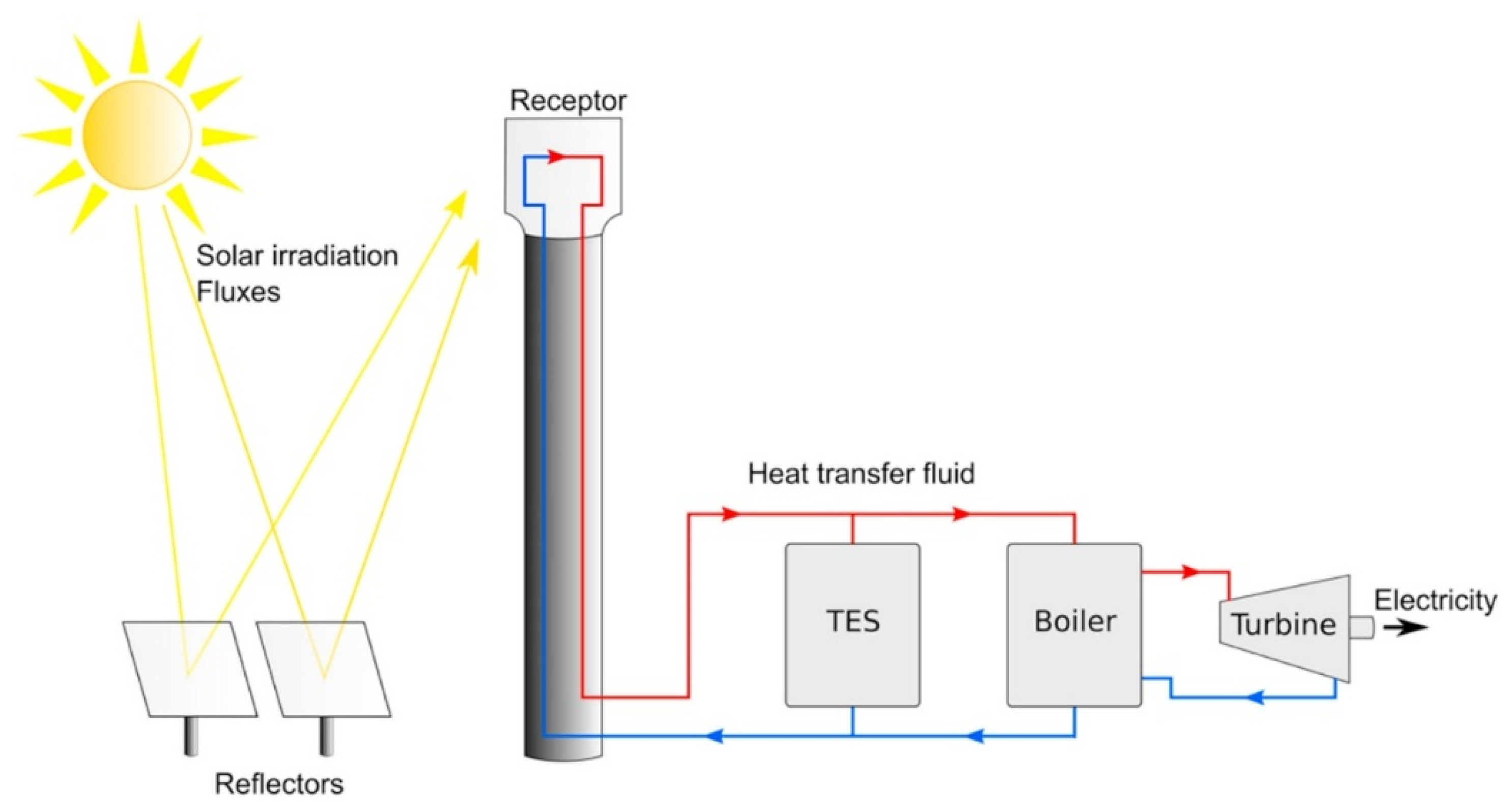
Solar energy is a renewable source of energy for electricity generation especially because it does not produce any harmful gases as opposed to conventional fossil fuel-run power plants. A major challenge in harvesting solar energy is the intermittency of the Sun’s availability due to weather, as well as diurnal and seasonal variations. Other issues include the mismatch in energy production and utilization, which has adverse effects on the overall efficiency of the system. Excess energy can be reversed if it is not completely managed or utilized, thus causing instability to the system, increased current faults, and protection mis-coordination [1]. When there is an over-demand, additional conventional resources are utilized to meet that demand, which eventually increases carbon footprint. Production side is highly non-deterministic because of its intermittent behavior, while utility patterns are also not uniform and there are peaks and ditches of energy consumption on the user side. This mismatch can be effectively damped by introducing an energy storage unit that will store the surplus energy by renewable means or the off-peak electricity by all types of resources. The stored energy can be used in case of non-availability of renewable sources [2,3,4]. For illustration, mechanism of the working principal of a heliostat-type concentrated solar power (CSP) plant with a thermal energy storage (TES) is shown in Figure 1. The TES unit is in between the solar receiver (receptor) and electricity generator (turbine), which acts as a surplus energy storage medium. The system is capable of mitigating transient variations in the solar energy supply that may be caused by cloudy weather conditions. It can also shift the power production from peak solar irradiance hours to peak electricity consumption hours. The system is helpful in increasing deployment and easy penetration of renewable energy technology by providing a consistent power supply to consumers.
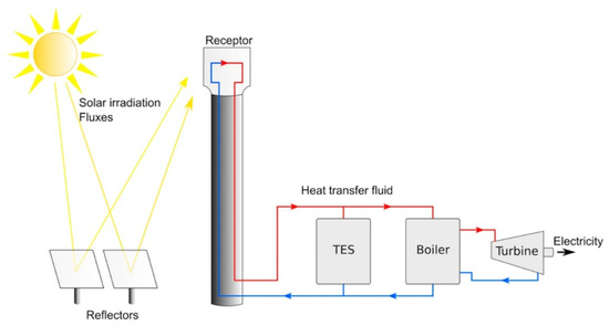
Figure 1.
Concentrated solar power plant with thermal energy storage system [5]. TES: thermal energy storage. (Reprint with permission [5]; 2019, Elsevier.)
For TES, materials are usually categorized into three forms: sensible heat storage—SHS (examples are water, air, oil, rocks, brine, concrete, sand, and soil), latent heat storage—LHS (organic, inorganic, eutectics, and low melting point metals), and thermochemical heat storage—THS (sorption and thermochemical). Latent heat storage commonly known as phase change materials (PCM) is preferred over sensible storage because of its high storage density and narrow range of phase transition [6]. However, the PCMs have problems of low thermal conductivity. Both sensible and latent storages can store heat for certain time (a few hours). Such TES systems cannot store energy for an entire season; for example, they cannot store surplus energy in summer when sunshine hours are longer and utilize this energy in the winter. For this purpose, THS is more viable as it involves high energy-intensive endothermic–exothermic reactions.
SHS is the most developed and widely used technology. In recent investigations for small-scale utility consumption, TES was equipped with photovoltaic (PV) arrays to store surplus energy and used either on weekends or during off-peak hours to damp cooling load in summer conditions [7]. The study used a water-to-water heat pump with the aim of charging the storage either on photovoltaic (PV) cells or using grid electricity [7]. Other studies also experimented with water as a medium in TES systems [8,9,10]. The system has small volumetric density and gravimetric density, can transport energy across small distances, and undergoes thermal losses. For LHS, many materials have been characterized, ranging in terms of latent heat of fusion from very low 74 kJ/kg (for inorganic PCMs) up to 1044 kJ/kg (for fluoride salt). Research is also established in the development, characterization, and stability testing of such materials [11,12]. THS is considered a relatively new concept that involves complex processes and high initial costs. Reported energy density ranges are 0.3 to 0.5 MJ/m3 for LHS and 0.5 to 3 MJ/m3 for THS [13].
Materials for LHS and THS are available in a wide range of operating temperatures; thus, a careful analysis is required for the optimal selection of material [14]. Heat transfer of the LHS system in general is not effective, and several methods and additives have been successfully implemented to make it more efficient. Its capability to store energy at ambient temperature without thermal losses is a feature of THS that makes it more preferable over LHS [15]. However, a wide range of investigation is still needed to make THS a viable storage system. One of the drawbacks of THS, as shown in a previous study, is the irreversibility of reaction in the initial tests, which makes the overall system less efficient [14]. However, among all thermochemical compounds, the reaction of calcium hydroxide with calcium oxide and water vapor makes THS stand out because of the low cost associated with the reaction, its global availability, and environmental friendliness of the reactants (limestone and water) involved.
The application of the storage system can increase the reintegration of waste heat to balance seasonal discrepancies between renewable electricity supply and heat demand. Despite these advantages, the design of cost-efficient reactors still remains a challenge due to unfavorable bulk properties of the raw material. In particular, the aspired gravity-assisted movement of the storage material under reaction conditions leads to increasingly complex reactor constructions [16].
Several reviews have been published recently on the performance, design, materials, and thermal fluids for a TES system in CSP plants. For instance, the integration of CSP technology with other renewable energy technology, such as wind and geothermal, for improved deployment and sharing of facilities to reduce cost is reviewed [17]. A study on global TES system-equipped CSP systems focused on thermo-chemical energy storage systems and also reviewed the merits and demerits of different integration strategies of TES with energy generation, including active systems, passive systems, and coupled systems [5]. Parabolic trough-based CSP systems without much focus on TES system were analyzed. The aim of the study was to present the state-of-the-art of parabolic trough-based technology with design parameters of its tube receiver, heat transfer enhancement through design modification, and by effective thermal fluids [18]. An overview of social life-cycle assessment of CSP plants in Spain is represented, which is a different concept and is not based on TES [19].
This review summarizes the recent advances in materials for thermal fluids, sensible, latent, and thermo-chemical energy storage systems with a comparison for adaptation to the technology. It highlights the core issues of TES in CSP technology and the proposed remedies in terms of high-temperature corrosion, life-cycle assessment, and economic analysis.
2. Materials for Thermal Fluids
One approach in the CSP plant is to generate superheated steam through solar absorber and directly run a turbine based on the subcritical Rankine cycle without any intervention of further heat exchanger. The option is economical but cannot accommodate the weather fluctuations. Furthermore, the system efficiency is also low. High temperatures for efficient thermodynamic cycles and improved heat transfer can improve the efficiency of the CSP plants, and thermal fluids play a vital role in this domain. For better performance, thermal fluids should have a low melting point and high thermal stability. They should be stable in a wide temperature range between its melting point and decomposition point with other favorable characteristics in terms of cost, availability, reactivity, and life [20]. Solar salt is the basic thermal fluid, with a melting and decomposition point of 220 °C and approximate 600 °C. Efforts are made on both end temperatures (melting and decomposition). A lower melting point is favorable to reduce the risk of freezing of materials in the circulation system and saving of heat tracing, whereas a higher decomposition temperature can run the efficient thermodynamic cycles.
Silicon carbides are among several potential additive materials in thermal fluids with excellent heat transfer coefficient values ranging from 140–500 W/m2·K and high thermal stability [21]. The addition of sodium nitrite to the traditional binary mixture (KNO3, NaNO3) reduced the melting temperature from 220 °C of the solar salt to 142 °C. However, the operating temperatures decreased from 600 to 454 °C during long-term operation [20]. Chen at el. developed solar salts with less variation in viscosities over a wider temperature range. This property of the material has a strong link with the heat transfer characteristics of the fluid and the energy required for circulation of the fluid [22]. The higher the viscosity, the more the fluid-resisting forces. The viscosities of the standard HITEC salt (53% KNO3, 7% NaNO3, and 47% NaNO2) decreased from 5 cP (centipoise) to almost 1.8 cP while increasing the temperature from 250 to 500 °C. However, the newly developed mixture of solar salt was much more stable, and the change in viscosity was almost 1.3 cP in the same temperature range, whereas the maximum value of viscosity was 3.5 cP [22]. Among commercially available thermal fluids, Therminol VP-I is the best performing material [23]. Table 1 contains the summary of different thermal fluids.

Table 1.
Summary of thermal fluids including their properties.
Among liquid metals, tin (Sn) is an excellent material for extremely high-temperature applications (>1300 °C). The reason is that at this temperature, a turbine (power generating unit of a CSP plant) can perform at approximately 60% efficiency. However, Sn is highly corrosive. This problem can be mitigated by encapsulating it in graphite, silicon carbide, and mullite [30]. Khanafer and Vafai reviewed thermal fluids for solar energy applications. Different metallic additives in water-based thermal fluid system are summarized [34].
3. Materials for Thermal Energy Storage
Thermal energy storage material is the key component to be considered in optimizing the design, operation, and cost of the CSP system. The material defines the feasibility of the system and makes it cost-comparable with conventional power plants. The desired characteristics of a TES material reported in [11,12] are given as
- (1)
- Phase transition temperature (solid–liquid in the case of PCM and chemical compositions in thermo-chemicals) should be in the operational temperature range of the CSP plant.
- (2)
- Volumetric density and energy storage density (latent heat, heat of reactions) should be maximum for a compact design.
- (3)
- Materials should have high and uniform specific heat capacity at different temperatures for accurate calculations in the design process.
- (4)
- Thermal conductivity of the material should be high for quick charging–discharging cycles.
- (5)
- It should have minimal or no super cooling of PCM and congruent melting.
- (6)
- It should be inexpensive and widely available.
- (7)
- The materials should have high thermal, chemical, and cyclic stability for an extended plant life.
- (8)
- In the case of PCM, there should be no volume changes during phase transition to curtail the issues of phase segregation.
- (9)
- The material should be non-flammable, non-toxic, and non-corrosive.
- (10)
- It should have a low vapor pressure.
Materials that were recently investigated for sensible, latent, and thermo-chemical energy storage systems are summarized in the subsequent sections.
3.1. Materials for Sensible Heat Storage
In this type of storage, materials absorb thermal energy as a means to increase the temperature of the material. Almost all type of materials can store heat through sensible means, but many of them are not suitable for TES application in CSP plants. Solar salt (a mixture of 60 wt.% sodium nitrate (NaNO3) and 40 wt.% potassium nitrate (KNO3)) is the most common sensible storage material [35]. The main problem with solar salt, however, is its susceptibility to decomposition at different levels of temperatures, which limits its use for applications above 550 °C [35] and gives it limited heat capacity. Awad at el. incorporated CuO nano-particles in solar salt by two different methods to increase its heat capacity and latent heat. The study successfully enhanced heat capacity by 22% at the maximum and latent heat capacity by 67% by modifying the compositions [36]. Sintered bauxite is another example of material for a sensible TES system [37]. For single pass, the thermal conversion and optical efficiency of the material were 84% and 60%, respectively, and the material was capable of achieving a temperature of more than 1100 °C when exposed to a heat flux of 150 kW/m2 [37]. Fasquelle at el. investigated alumina spheres as TES systems in a thermocline tank with dibenzyltoluene as a synthetic oil, and they achieved 93.5% energy storage efficiency at the maximum [38]. Li and Ju researched the effect of thermal cycles in the temperature range of 20–650 °C on the stability of granite (natural rock) as a storage medium for TES system. It was found that granite is a potential material for such application because its thermo-mechanical properties remain stable even after five thermal cycles [39]. As alternative materials, concrete had been researched using TRNSYS modelling for TES [40]. In another study, it was reported that concrete is a superior material for TES application because of better thermal and mechanical properties over a long period of time. Initial experiments at lab scale and in prototype showed good results, and the material was to be tested in actual field experiments at the Masdar Institute Solar Platform (MISP) in the United Arab Emirates [41]. Recently, dune sand had been investigated as a sensible energy storage system. The material was characterized for its heat capacity, thermal cycling stability, and agglomeration. It was reported that sand can be used for TES system in the range of 800–1000 °C; however, minor agglomeration starts above 800 °C and the sand becomes solid above 1000 °C [42].
Furthermore, waste materials have also been investigated for their potential applications in TES systems. For instance, slag—a waste material from the steel and iron industries—is an environmental burden, which has the possibility to be a potential candidate in the TES system. The material has stable thermal properties from ambient temperature to 1000 °C [43]. Mohan et. al compiled specifically the sensible heat storage materials with operating temperature more than 600 °C [44]. The study focused on the different salts and also pointed out the barriers in the deployments of these materials into CSP technology without resolving the associated problems [44].
3.2. Materials for Latent Heat Storage
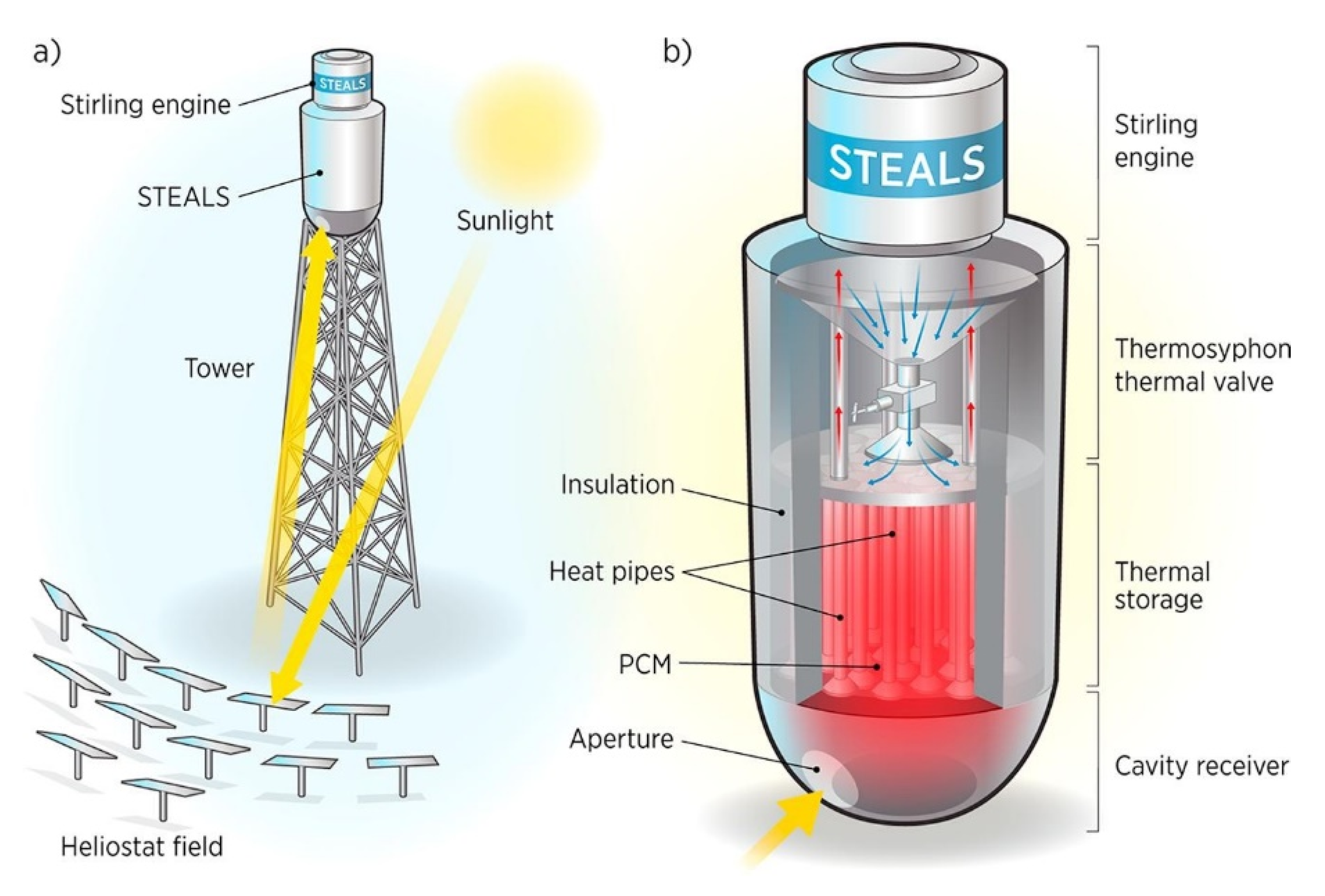
In this type of storage, heat is stored in the form of phase transition, generally from solid to liquid. The material returns back to its solid state when heat is extracted from it. In a recent novel approach, a PCM storage and power generator was designed just above a solar tower to reduce parasitic losses and to make the design compact, as shown in Figure 2. The system is capable of operating on a cost range similar to the peaking plants fueled by natural gas [45]. Table 2 shows the summary of properties of phase change materials that have gained attention in the last decade. General understanding of these materials involves inorganic salts; however, metallic alloys in particular are better in terms of thermal conductivity. The order of thermal conductivity for metallic alloys is at least two times higher than salts [46]. Risueño et al. investigated different zinc alloys with the melting range 344–371 °C. Latent heat of fusion of the alloys ranged from 106 to 132 kJ/kg and their thermal conductivity ranged from 66–139 W.m−1k−1 in solid phase [47]. The same group further experimentally investigated the post-thermal cycling effects on the chemical compositions and thermo-physical properties of the alloys by exposing the alloys to 100–500 freeze-thaw cycles. The investigations endorsed the materials for possible applications in the TES systems for CSP plants [48]. In a recent study, tubular sodium boiler system was investigated, which was coupled with a NaCl-based TES system [49,50]. In the system, sodium underwent the phase transitions between liquid and gas. The research proceeded until it resolved the issue of boiling instability of sodium [49,50].
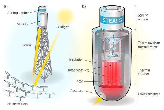
Figure 2.
Design of heliostat type concentrated solar power (CSP) plant [45]. (Reprint with permission [45]; 2019, Elsevier.)

Table 2.
Summary of the material properties of newly investigated phase change materials (PCMs).
3.3. Materials for Thermochemical Energy Storage
In this type of storage, heat is stored in the form of reversible reaction of different chemicals. At a certain temperature, reactants react with each other and form new compositions. The process is highly endothermic, which means it consumes a lot of heat. This step is called charging, and surplus heat is stored in the products. At the time of heat recovery, a highly exothermic reversible reaction occurs. Thermochemical materials have the maximum energy storage density among all others. For instance, MgSO4-zeolite has the energy storage density of 640 kJ/kg [56]. The summary of advanced thermo-chemical materials is presented in Table 3.

Table 3.
Summary of recent materials with their properties for thermo-chemical energy storage.
The characteristics of the different TES systems are compared in Table 4.

Table 4.
Comparison of different energy storage systems.
4. Limitations of Thermal Energy Storage Systems and Their Proposed Solutions
The subsequent sections contain the limitations of contemporary TES systems. Different approaches to mitigate these issues also have been summarized.
4.1. High-Temperature Corrosion
One critical issue in TES for high-temperature applications is corrosion of the TES containment materials, which incurs a corrosion cost of up to 3–5% volume of industrialized countries’ gross national product [59]. Most of the molten salts used for TES are highly corrosive. The reactions of salts and the subsequent occurrence of corrosion is not completely understood, and the problem still needs attention, especially in the context of stress corrosion cracking in molten salt media [60]. The corroded layer is either in the form of an oxide layer on the container or degradation of the container material. Standard structural materials (stainless steel or carbon) degrade after coming in contact with salt chlorides by the chloridation [61]. Initial testing of an anti-corrosion coating was conducted on steel products with minor improvements in the protection against corrosion [61]. In certain cases, thermal properties enhancing nanoparticles agglomerate and form clusters over a period of time. This agglomeration of nanoparticles weakens the performance of thermal fluids [62,63]. A quaternary salt with low melting point (85.4 °C), wide operating range (600 °C), reduced risk of blockage, and good corrosion resistance was recently developed [29,64]. A recent review conducted detailed investigations of corrosion in CSP plants [65]. The study claimed that the risk of corrosion by the use of molten salt could not be eliminated; however, the effect could be protected against corrosion using a corrosion-resistant container. Several coating materials and methods have been summarized to reduce the effect and severity of corrosion caused by molten salts [65]. Different grades of steel as a container for high-temperature energy storage materials have been proposed, as given below [35]:
- Low alloy carbon steel (≤400 °C) [35].
- Cr–Mo steel (≤500 °C) (Cr-content up to about 9 wt %) [35].
- Stainless Cr–Ni steel (≤570 °C) (with and without alloying elements as Mo, Nb, Ti) [35].
- Ni alloys (≤650 °C) (i.e., Alloy 800) [35].
Recently, addition of nanoparticles into molten salts has been linked to the increase in corrosion. It was observed that interparticle porosity and entrapped air increased the corrosion rate by 2 to 3 times the actual rate. The addition of different particles also increased the non-uniformity in coating due to non-uniform corrosion [66]. Fernández and Cabeza recently reviewed the corrosion mechanisms involving nitrate-based salts in TES systems for CSP [59]. Some of the general approaches to protect corrosion are [59]
- Tuning the composition of container by increasing the non-reactive content;
- Removal of impurities in molten salt systems or the addition of inhibitors;
- Surface treatment.
Rea et al. used aluminum (88%)–silicon (12%) eutectic alloy as a PCM in their investigations to produce less costly electricity using CSP technology [51]. The eutectic PCM was contained in steel, and in its molten form it decays the steel container at a high rate. A protective coating (MgO–Zr2O3) was applied using plasma spray method onto the steel components vulnerable to corrosion. Within a short experimentation of 4 days, it was observed that the protective coating failed at some locations and it exposed the container material to the PCM. Due to the corrosion, thickness of steel reduced from 2.4 to 0.36 mm in just 4 days. A little more time can cause the failure of the storage tank and can cause leakage of the PCM [51]. Grosu et al. developed a calcium carbonate layer onto steel to inhibit corrosion. The corrosion tests were conducted under inert and air exposure conditions with isothermal temperature up to 500 °C [67]. The layer was stable in the tests; however, dynamic testing is required to verify the efficacy of the layer. Furthermore, the presence of layer onto the whole steel structure is extremely important to avoid localized corrosion [67]. Problems of such corrosion are not only the failure of the container—reaction of iron in steel with the eutectic PCM forms non-melting aluminides which cannot work for the next cycle of melting–freezing [68]. Binder and Haussener proposed design guidelines to contain the Al–Si eutectic PCM into 316L steel through their prolonged investigations. However, the investigations were based on the constant temperature conditions, which may have different outcomes as compared to the actual transient temperatures [68]; hence, research is undergoing to accommodate all real conditions. Many alternatives based on the reactive materials and corresponding types are proposed for corrosion resistance [44]. Fernandez et al. tested alumina-forming austenite alloys for corrosion resistance. Although the samples were corroded, the rate of corrosion was considerable [69,70]. Ding et al. investigated the commercial alloys in the neutral environment by exposure to different PCM at 700 °C for more than 500 hours. Unfortunately, all the alloys could not qualify for high temperature applications because of the corrosion rate above the recommended level considering a 30 year lifetime of the system [71].
One way to handle the issue is the addition of corrosion inhibitor into the reactive material [72]. Another approach to circumvent the corrosion problem is to encapsulate the reactive materials into stable and non-reactive shell material prior to their functioning [12]. Zhang et al. developed silica shell around reactive bicarbonate salts with the melting point and heat of fusion of 540 °C and 220 kJ/kg, respectively [73,74].
4.2. Life Cycle Assessment of TES
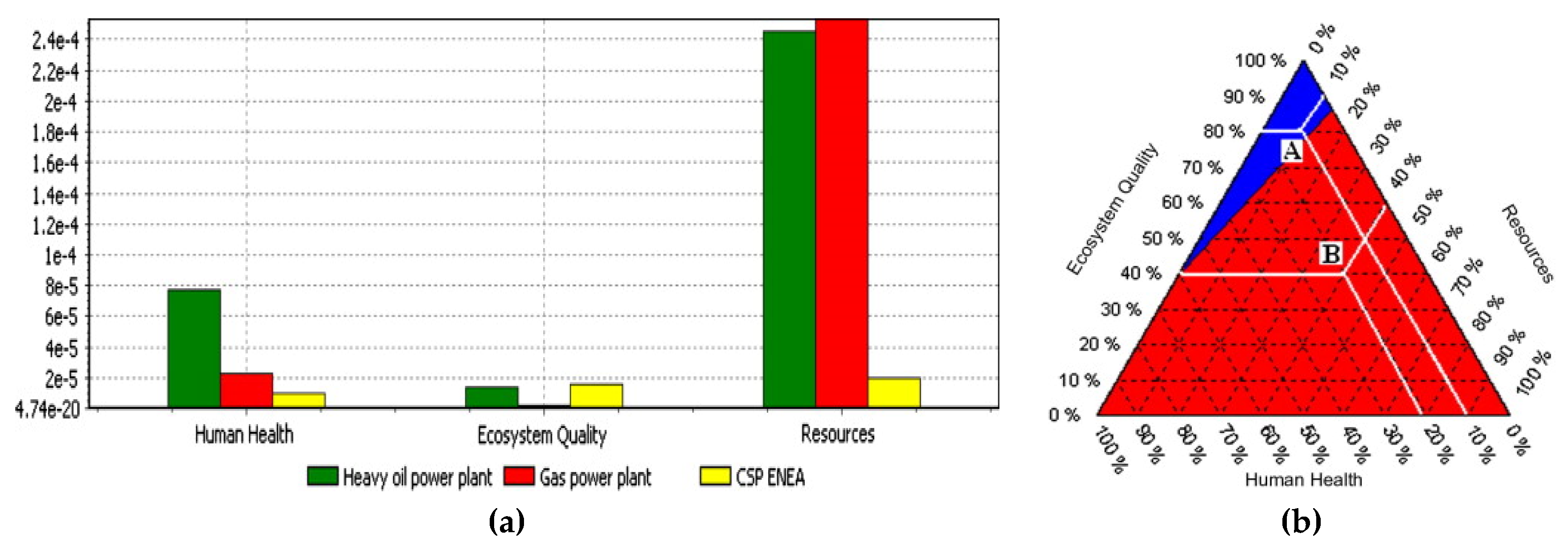
A life cycle assessment (LCA), also known as life cycle analysis, is a technique to assess environmental impacts associated with all stages of a product’s life (i.e., from raw material extraction through materials processing, manufacturing, distribution, usage, repair and maintenance, through to disposal or recycling). However, LCA of TES in CSP plants is one the least studied topics in energy storage, and there is a large gap of knowledge in this area. LCA presents a comparative assessment of the environmental issues involving the technology. In the case of operational environmental impacts of renewable energy technologies, most results would be misleading because the factor involved is too small. Rather, LCA is much needed to present a clearer picture, starting from the extractions of materials to the usage through to its eventual disposal. A piece of research reported that molten salt produces the maximum environmental impact per kilowatt–hour (kWh) energy storage in comparison with the concrete- and PCM-based storage systems [75]. The reason is that molten salt system is highly complex and involves more materials. Furthermore, the environmental impact of molten salt is less in the case of PCM storage when compared to sensible storage [75]. Another study on a CSP plant in Spain reported nitrate solution and design of steel-made storage as causing a major environmental impact [76]. Another study compared the LCA of three power plants fueled by oil, gas, and solar power by considering three factors—human health, ecosystem, and resources. Eco-indicator 99 revealed that although the environmental impact of a CSP plant is significantly lower on human health and resources, it is still significantly higher than a gas power plant, as shown in Figure 3a [77]. The two competing technologies were further analyzed using a “mixing triangle approach”, depending on the magnitude of damage caused to the each factor, which is represented in Figure 3b. In this approach, a CSP plant is preferable over an oil/gas plant, as more weightage is given to health and resource depletion as compared to the ecosystem [77]. Here, points A and B represent the two different considered scenarios, whereas A reflects 80% ecosystem, 10% resources, and 10% health. Gas plants perform better on the basis of these parameters as compared to the CSP; however, it will deplete the resources quickly. On the other hand, considering point B with 40% ecosystem, 40% resources, and 20% health, the performance of a CSP plant is better than that of a gas power plant.
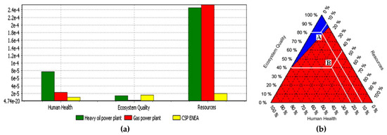
Figure 3.
Comparison of the global impact of CSP plant vs. gas power plant: (a) damage-oriented approach and (b) mixing triangle approach [77]. (Reprint with permission [77]; 2019, Elsevier.)
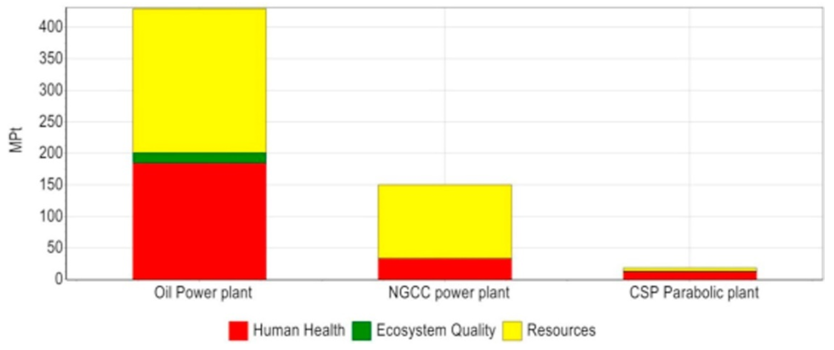
A more recent study compared LCA of an oil power plant, natural gas combined cycle (NGCC) power plant, and CSP parabolic plant against three categories—human health, ecosystem quality, and resources. The CSP plant was shown to have the least damaging factor in all categories, as shown in Figure 4 [78]. Table 5 is the summary of findings of the recent LCA investigations of TES systems.
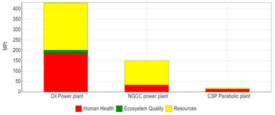
Figure 4.
Comparison of the three power plants using the single score indicator [78]. (Reprint with permission [78]; 2019, Elsevier.)

Table 5.
Summary of the CSP and TES life cycle assessment studies in CSP technologies.
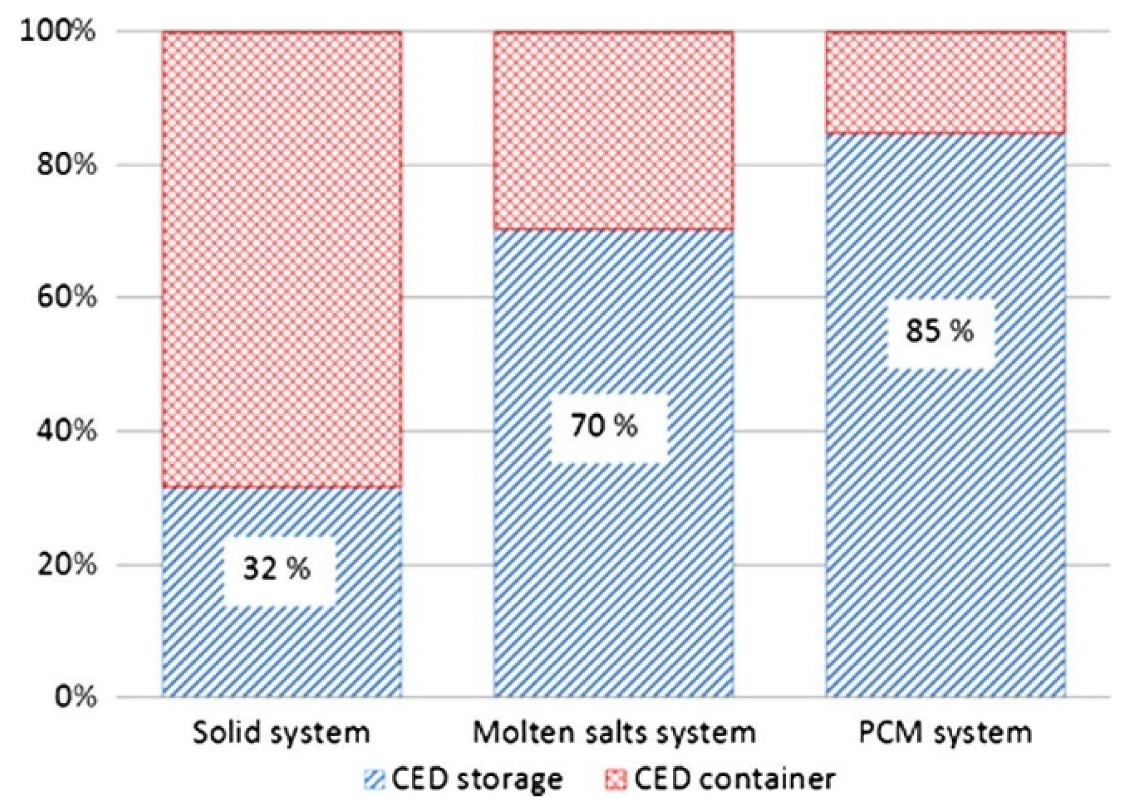
Embodied energy for container and storage materials, including solid storage, molten salt storage, and PCM-based storage is shown in Figure 5.
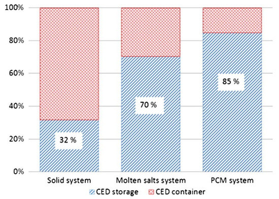
Figure 5.
Influence of storage materials and container-embodied energy for the three systems [79]. (Reprint with permission [79]; 2019, Elsevier.)
4.3. Economic Analysis of TES
A feasible cost of any new technology is the deciding factor for its market penetration. To make the price of electricity generated through CSP comparable to that of other renewable energies, development of alternative inexpensive materials, optical and thermal efficiency of the individual components within the overall CSP plant, and integration of TES for dispatchability are prime factors [89]. Energy storage density is an important factor influencing the cost of TES because of the size of storage tanks and because the thermal storage material is dependent on it [16,90]. Energy requirement for auxiliary resources is another factor that influences efficiency and cost [16]. However, the effect of thermal efficiency of a TES system on the system cost is comparatively low [16]. Cost of the system can be reduced by some simple techniques. For example, to enhance the thermophysical properties of molten salts, different additives are recommended, although these additives are associated with other challenges such as accelerated corrosion. For instance, addition of CuO nanoparticles (1% wt.) in nitrate molten salt increased the specific heat capacity, sensible-, and latent-energy storage by 21.24%, 9.27%, and 67%, respectively. However, the CuO nanoparticles, when purchased directly from commercial suppliers, are too costly. Alternatively, these particles can be produced by the evaporation of CuSO4·5H2O using one-step method [36]. The commercial product of CuO nanoparticles costed £60.5 for 25 grams, whereas the same amount can be produced by evaporation for £6.83, approximately nine times lower cost than the commercial product [36]. Pacheco at el. developed a thermocline storage for TES employing a single tank instead of two storage tanks, which works on the principle of thermal gradient. The system is 33% less costly when compared to the two-tank storage systems [91]. Zurita et al. investigated the coupling of TES system and battery storage system with a hybrid PV and CSP plant for techno-economic evaluation. The study revealed that 60% to 90% cost reduction of the battery storage system is mandatory for the system to be economically comparable to that of set-targets [92]. The studies related to cost analysis of thermal energy storage for CSP are summarized in Table 6.

Table 6.
Cost analysis of different pieces of research by incorporating thermal energy storage into concentrated solar power plant.
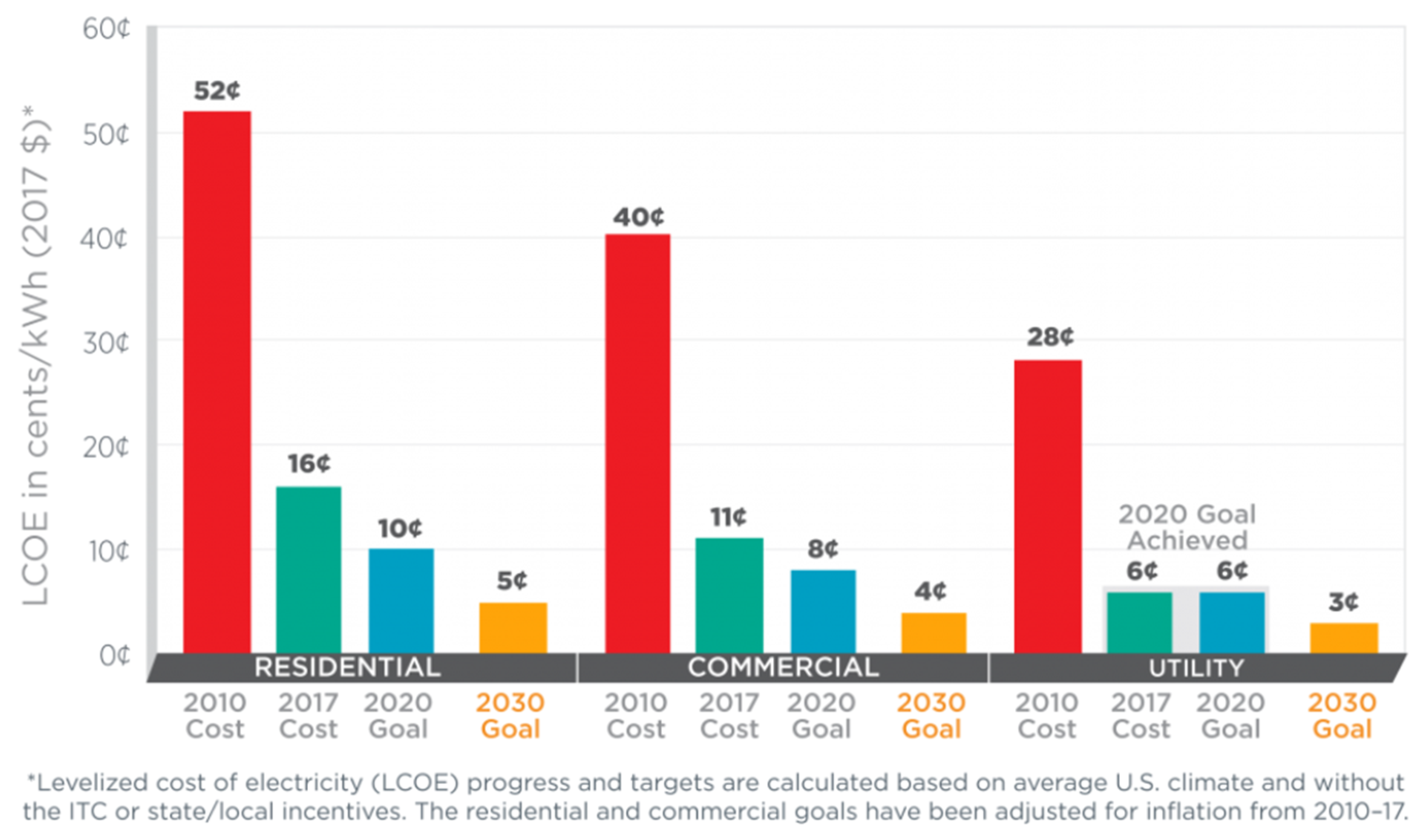
The United States Department of Energy (DOE) announced a project “The SunShot Initiative” in 2011 with the aim of reducing the levelized cost of electricity (LCOE) by 75%, done by producing the utility-scale electricity through CSP plants with a cost of less than 6¢/kWh by 2020 [100]. LCOE is the total cost divided by the total power generation. With the initiative, active- and target-oriented research has been conducted in the recent past. For example, an extremely novel modular design of 100 kWelectric has been proposed that can be scaled up or down in the range of 10 to 1000 kWelectric with a cost variation of only 3%. In the design, solar receiver, thermal energy storage unit, and power block unit are placed on top of each other, all on one tower. Currently, the Stirling engine is considered; however, the system is capable of integration with other power cycles. With minor improvements in the parameters, authors believe that production of electricity from such CSP plants is at 8.1¢/kWh [45]. Rea et al. investigated the location-based economic analysis for CSP technology because latitude, weather conditions, and availability of labor in that particular region influence the cost of the system [101]. The study compared the effect of a single 100 kWelectric plant with a cluster of many small plants with the same output. This approach is highly important in decentralization, application of such systems for remote areas, or integration of these with microgrids for uniform distribution [101]. Tehrani et al. worked on different combinations of PCMs and their design parameters. Instead of LCOE method, storage specific cost was considered for comparison of different systems. This cost was the storage cost divided by the storage capacity. Researchers reported a specific cost reduction of 62% in the case of dual-media thermocline with concrete system as compared to the two-tank molten salt storage system [102]. Le et al. performed economic analysis of a project in Binh Thuan. The LCOE of the system was 21¢/kWh [103]. Lindquist et al. modelled a modular CSP plant with varying electricity production capacity using a Stirling engine, primarily for the conditions of Morocco. The study investigated multiple systems with varying storage times. It was reported that LCOE reduces when capacity of the CSP plant is increased; however, the solar-to-electricity conversion efficiency is lowered with the increment in capacity [104].
With the rigorous efforts in the last decade in CSP technology, United States DOE achieved its 2020 goal for the utility scale energy production through CSP in 2017, 3 years earlier than projected [100]. Interestingly, the new targets were set by the end of 2030 to reduce the cost of the solar energy to even lower. Comparisons of the set and achieved targets are illustrated in Figure 6. For residential and commercial sectors, research is ongoing to meet the 2020 and 2030 targets.
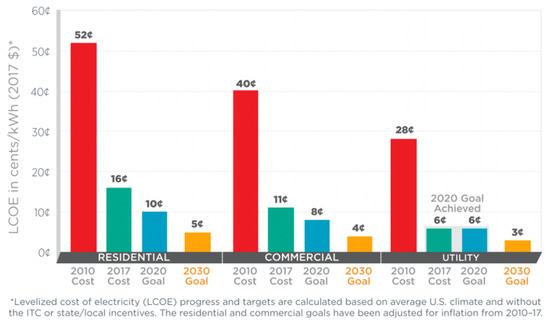
Figure 6.
Targets of SunShot Initiative and goals [100]. ITC: investment tax credit.
5. Conclusions
Concentrated solar power has the potential to meet global energy demand, but inherent intermittency is the main obstacle to fulfilling this potential. To circumvent the issue, thermal energy storage is a sound option for continuous power production and shifting the solar energy of peak sunshine hours to peak consumption hours. Molten salts are the most researched materials for such storage. However, molten salt-based storage damages the environment as opposed to solid storage or PCM storage. The need of the hour is to find more environmentally friendly materials and simpler designs interfaced with simple control systems. Corrosion is another important issue associated with molten salts, which reduces the life span of the CSP plants and hence incurs huge costs.
Author Contributions
Conceptualization and methodology, F.A. and Y.R.; writing, review, and editing, F.A. and Y.R.
Funding
This research was funded by the United Arab Emirates University-National Water Center through grants (31R153-Research Center-NWC), and the ADEK Award for Research Excellence (AARE) for grant no. 21N220-AARE18-089
Acknowledgments
The authors would like to express their appreciation to United Arab Emirates University (UAEU) to facilitate the research.
Conflicts of Interest
The authors declare no conflict of interest.
Nomenclature
| Acronyms | |
| CSP | Concentrated solar power |
| DOE | United States Department of Energy |
| HTF | Heat transfer fluid |
| ITC | Investment tax credit |
| LCA | Life cycle assessment |
| LCOE | Levelized cost of electricity |
| LHS | Latent heat storage |
| NGCC | Natural gas combined cycle |
| PCM | Phase change material |
| PV | Photovoltaics |
| SHS | Sensible heat storage |
| TES | Thermal energy storage |
| THS | Thermochemical heat storage |
| Measurement units | |
| Heat capacity | kJ/kg.K |
| Heat flux | kW/m2 |
| Heat transfer coefficient | W/m2.K |
| Latent heat of fusion | kJ/kg |
| Temperature | °C |
| Thermal conductivity | W/m.K |
| Volumetric energy density | MJ/m3 |
| Viscosity | cP |
References
- Chojnowski, T.; LaPlante, D.; Truong, J. Reverse Power Mitigation System for Photovoltaic Energy Resources; Worcester Polytechnic Institute: Worcester, MA, USA, 2015. [Google Scholar]
- Geng, K.; Ai, X.; Liu, B. A Two-Stage Scheduling Optimization Model and Corresponding Solving Algorithm for Power Grid Containing Wind Farm and Energy Storage System Considering Demand Response. DEStech Trans. Eng. Technol. Res. 2017. [Google Scholar] [CrossRef]
- Cisek, P.; Taler, D. Numerical and experimental study of a solid matrix Electric Thermal Storage unit dedicated to the environmentally friendly residential heating system. Energy Build. 2016, 130, 747–760. [Google Scholar] [CrossRef]
- Cisek, P.; Taler, D. Numerical analysis and performance assessment of the Thermal Energy Storage unit aimed to be utilized in Smart Electric Thermal Storage (SETS). Energy 2019, 173, 755–771. [Google Scholar] [CrossRef]
- Pelay, U.; Luo, L.; Fan, Y.; Stitou, D.; Rood, M. Thermal energy storage systems for concentrated solar power plants. Renew. Sustain. Energy Rev. 2017, 79, 82–100. [Google Scholar] [CrossRef]
- Barlev, D.; Vidu, R.; Stroeve, P. Innovation in concentrated solar power. Sol. Energy Mater. Sol. Cells 2011, 95, 2703–2725. [Google Scholar] [CrossRef]
- Arteconi, A.; Ciarrocchi, E.; Pan, Q.; Carducci, F.; Comodi, G.; Polonara, F.; Wang, R. Thermal energy storage coupled with PV panels for demand side management of industrial building cooling loads. Appl. Energy 2017, 185, 1984–1993. [Google Scholar] [CrossRef]
- Baeten, B.; Rogiers, F.; Helsen, L. Reduction of heat pump induced peak electricity use and required generation capacity through thermal energy storage and demand response. Appl. Energy 2017, 195, 184–195. [Google Scholar] [CrossRef]
- Patteeuw, D.; Bruninx, K.; Arteconi, A.; Delarue, E.; D’haeseleer, W.; Helsen, L. Integrated modeling of active demand response with electric heating systems coupled to thermal energy storage systems. Appl. Energy 2015, 151, 306–319. [Google Scholar] [CrossRef]
- Kim, Y.; Norford, L.K. Optimal use of thermal energy storage resources in commercial buildings through price-based demand response considering distribution network operation. Appl. Energy 2017, 193, 308–324. [Google Scholar] [CrossRef]
- Hassan, A.; Shakeel Laghari, M.; Rashid, Y. Micro-Encapsulated Phase Change Materials: A Review of Encapsulation, Safety and Thermal Characteristics. Sustainability 2016, 8, 1046. [Google Scholar] [CrossRef]
- Alva, G.; Liu, L.; Huang, X.; Fang, G. Thermal energy storage materials and systems for solar energy applications. Renew. Sustain. Energy Rev. 2017, 68, 693–706. [Google Scholar] [CrossRef]
- Abedin, A.H. A Critical Review of Thermochemical Energy Storage Systems. Open Renew. Energy J. 2011, 4, 42–46. [Google Scholar] [CrossRef]
- Solé, A.; Martorell, I.; Cabeza, L.F. State of the art on gas–solid thermochemical energy storage systems and reactors for building applications. Renew. Sustain. Energy Rev. 2015, 47, 386–398. [Google Scholar] [CrossRef]
- Pardo, P.; Deydier, A.; Anxionnaz-Minvielle, Z.; Rougé, S.; Cabassud, M.; Cognet, P. A review on high temperature thermochemical heat energy storage. Renew. Sustain. Energy Rev. 2014, 32, 591–610. [Google Scholar] [CrossRef]
- Bayon, A.; Bader, R.; Jafarian, M.; Fedunik-Hofman, L.; Sun, Y.; Hinkley, J.; Miller, S.; Lipiński, W. Techno-economic assessment of solid–gas thermochemical energy storage systems for solar thermal power applications. Energy 2018, 149, 473–484. [Google Scholar] [CrossRef]
- Powell, K.M.; Rashid, K.; Ellingwood, K.; Tuttle, J.; Iverson, B.D. Hybrid concentrated solar thermal power systems: A review. Renew. Sustain. Energy Rev. 2017, 80, 215–237. [Google Scholar] [CrossRef]
- Fuqiang, W.; Ziming, C.; Jianyu, T.; Yuan, Y.; Yong, S.; Linhua, L. Progress in concentrated solar power technology with parabolic trough collector system: A comprehensive review. Renew. Sustain. Energy Rev. 2017, 79, 1314–1328. [Google Scholar] [CrossRef]
- Corona, B.; Bozhilova-Kisheva, K.P.; Olsen, S.I.; San Miguel, G. Social Life Cycle Assessment of a Concentrated Solar Power Plant in Spain: A Methodological Proposal: Social-LCA of a CSP Plant in Spain: Method Proposal. J. Ind. Ecol. 2017, 21, 1566–1577. [Google Scholar] [CrossRef]
- Dunlop, T.O.; Jarvis, D.J.; Voice, W.E.; Sullivan, J.H. Stabilization of molten salt materials using metal chlorides for solar thermal storage. Sci. Rep. 2018, 8, 8190. [Google Scholar] [CrossRef]
- Flamant, G.; Gauthier, D.; Benoit, H.; Sans, J.-L.; Garcia, R.; Boissière, B.; Ansart, R.; Hemati, M. Dense suspension of solid particles as a new heat transfer fluid for concentrated solar thermal plants: On-sun proof of concept. Chem. Eng. Sci. 2013, 102, 567–576. [Google Scholar] [CrossRef]
- Chen, Y.; Wu, Y.; Ren, N.; Ma, C. Experimental study of viscosity characteristics of high-temperature heat transfer molten salts. Sci. China Technol. Sci. 2011, 54, 3022–3026. [Google Scholar] [CrossRef]
- Peiró, G.; Gasia, J.; Miró, L.; Prieto, C.; Cabeza, L.F. Influence of the heat transfer fluid in a CSP plant molten salts charging process. Renew. Energy 2017, 113, 148–158. [Google Scholar] [CrossRef]
- Peng, Q.; Yang, X.; Wei, X.; Yang, J.; Ding, J.; Lu, J. New molten salt heat transfer fluid for solar thermal power plant. In Proceedings of the 2013 International Conference on Materials for Renewable Energy and Environment, Chengdu, China, 19–21 August 2013; pp. 496–499. [Google Scholar]
- Peng, Q.; Ding, J.; Wei, X.; Yang, J.; Yang, X. The preparation and properties of multi-component molten salts. Appl. Energy 2010, 87, 2812–2817. [Google Scholar] [CrossRef]
- Paul, T.C.; Morshed, A.K.M.M.; Fox, E.B.; Khan, J.A. Thermal performance of Al2O3 Nanoparticle Enhanced Ionic Liquids (NEILs) for Concentrated Solar Power (CSP) applications. Int. J. Heat Mass Transf. 2015, 85, 585–594. [Google Scholar] [CrossRef]
- Paul, T.C.; Morshed, A.K.M.M.; Khan, J.A. Effect of Nanoparticle Dispersion on Thermophysical Properties of Ionic Liquids for its Potential Application in Solar Collector. Procedia Eng. 2014, 90, 643–648. [Google Scholar] [CrossRef][Green Version]
- Paul, T.C.; Morshed, A.K.M.M.; Fox, E.B.; Khan, J.A. Enhanced thermophysical properties of NEILs as heat transfer fluids for solar thermal applications. Appl. Therm. Eng. 2017, 110, 1–9. [Google Scholar] [CrossRef]
- Chen, X.; Wu, Y.; Zhang, L.; Wang, X.; Ma, C. Experimental study on the specific heat and stability of molten salt nanofluids prepared by high-temperature melting. Sol. Energy Mater. Sol. Cells 2018, 176, 42–48. [Google Scholar] [CrossRef]
- Zhang, Y.; Cai, Y.; Hwang, S.; Wilk, G.; DeAngelis, F.; Henry, A.; Sandhage, K.H. Containment materials for liquid tin at 1350 °C as a heat transfer fluid for high temperature concentrated solar power. Sol. Energy 2018, 164, 47–57. [Google Scholar] [CrossRef]
- Montes, M.J.; Abánades, A.; Martínez-Val, J.M.; Valdés, M. Solar multiple optimization for a solar-only thermal power plant, using oil as heat transfer fluid in the parabolic trough collectors. Sol. Energy 2009, 83, 2165–2176. [Google Scholar] [CrossRef]
- Technical Data Sheet Therminol® VP-1 Heat Transfer Fluid. Available online: https://www.therminol.com/sites/therminol/files/documents/Therminol-VP1-TechDatasheet.pdf (accessed on 11 July 2019).
- Vidal, J.C.; Klammer, N. Molten chloride technology pathway to meet the US DOE sunshot initiative with Gen3 CSP. In Proceedings of the AIP Conference 2019, Saint-Martin-d’Hères, France, 8–12 July 2019; Volume 2126, No. 1. p. 080006. [Google Scholar]
- Khanafer, K.; Vafai, K. A review on the applications of nanofluids in solar energy field. Renew. Energy 2018, 123, 398–406. [Google Scholar] [CrossRef]
- Bauer, T.; Pfleger, N.; Breidenbach, N.; Eck, M.; Laing, D.; Kaesche, S. Material aspects of Solar Salt for sensible heat storage. Appl. Energy 2013, 111, 1114–1119. [Google Scholar] [CrossRef]
- Awad, A.; Burns, A.; Waleed, M.; Al-Yasiri, M.; Wen, D. Latent and sensible energy storage enhancement of nano-nitrate molten salt. Sol. Energy 2018, 172, 191–197. [Google Scholar] [CrossRef]
- Xiao, G.; Guo, K.; Luo, Z.; Ni, M.; Zhang, Y.; Wang, C. Simulation and experimental study on a spiral solid particle solar receiver. Appl. Energy 2014, 113, 178–188. [Google Scholar] [CrossRef]
- Fasquelle, T.; Falcoz, Q.; Neveu, P.; Hoffmann, J.-F. A temperature threshold evaluation for thermocline energy storage in concentrated solar power plants. Appl. Energy 2018, 212, 1153–1164. [Google Scholar] [CrossRef]
- Li, B.; Ju, F. Thermal stability of granite for high temperature thermal energy storage in concentrating solar power plants. Appl. Therm. Eng. 2018, 138, 409–416. [Google Scholar] [CrossRef]
- Buscemi, A.; Panno, D.; Ciulla, G.; Beccali, M.; Lo Brano, V. Concrete thermal energy storage for linear Fresnel collectors: Exploiting the South Mediterranean’s solar potential for agri-food processes. Energy Convers. Manag. 2018, 166, 719–734. [Google Scholar] [CrossRef]
- Martins, M.; Villalobos, U.; Delclos, T.; Armstrong, P.; Bergan, P.G.; Calvet, N. New Concentrating Solar Power Facility for Testing High Temperature Concrete Thermal Energy Storage. Energy Procedia 2015, 75, 2144–2149. [Google Scholar] [CrossRef]
- Diago, M.; Iniesta, A.C.; Soum-Glaude, A.; Calvet, N. Characterization of desert sand to be used as a high-temperature thermal energy storage medium in particle solar receiver technology. Appl. Energy 2018, 216, 402–413. [Google Scholar] [CrossRef]
- Ortega-Fernández, I.; Calvet, N.; Gil, A.; Rodríguez-Aseguinolaza, J.; Faik, A.; D’Aguanno, B. Thermophysical characterization of a by-product from the steel industry to be used as a sustainable and low-cost thermal energy storage material. Energy 2015, 89, 601–609. [Google Scholar] [CrossRef]
- Mohan, G.; Venkataraman, M.B.; Coventry, J. Sensible energy storage options for concentrating solar power plants operating above 600 °C. Renew. Sustain. Energy Rev. 2019, 107, 319–337. [Google Scholar] [CrossRef]
- Rea, J.E.; Oshman, C.J.; Olsen, M.L.; Hardin, C.L.; Glatzmaier, G.C.; Siegel, N.P.; Parilla, P.A.; Ginley, D.S.; Toberer, E.S. Performance modeling and techno-economic analysis of a modular concentrated solar power tower with latent heat storage. Appl. Energy 2018, 217, 143–152. [Google Scholar] [CrossRef]
- Risueño, E.; Doppiu, S.; Rodríguez-Aseguinolaza, J.; Blanco, P.; Gil, A.; Tello, M.; Faik, A.; D’Aguanno, B. Experimental investigation of Mg-Zn-Al metal alloys for latent heat storage application. J. Alloys Compd. 2016, 685, 724–732. [Google Scholar] [CrossRef]
- Risueño, E.; Faik, A.; Gil, A.; Rodríguez-Aseguinolaza, J.; Tello, M.; D’Aguanno, B. Zinc-rich eutectic alloys for high energy density latent heat storage applications. J. Alloys Compd. 2017, 705, 714–721. [Google Scholar] [CrossRef]
- Risueño, E.; Faik, A.; Gil, A.; Rodríguez-Aseguinolaza, J.; Tello, M.; D’Aguanno, B. Thermal cycling testing of Zn–Mg–Al eutectic metal alloys as potential high-temperature phase change materials for latent heat storage. J. Therm. Anal. Calorim. 2017, 129, 885–894. [Google Scholar] [CrossRef]
- Niedermeier, K.; Marocco, L.; Flesch, J.; Mohan, G.; Coventry, J.; Wetzel, T. Performance of molten sodium vs. molten salts in a packed bed thermal energy storage. Appl. Therm. Eng. 2018, 141, 368–377. [Google Scholar] [CrossRef]
- Coventry, J.; Pye, J.; Kumar, A.; Iyer, S.; Kee, Z.; Lipiński, W. A sodium boiler and phase-change energy storage system. In Proceedings of the AIP Conference 2019, Saint-Martin-d’Hères, France, 8–12 July 2019; Volume 2126, No. 1. p. 060002. [Google Scholar]
- Rea, J.E.; Oshman, C.J.; Singh, A.; Alleman, J.; Parilla, P.A.; Hardin, C.L.; Olsen, M.L.; Siegel, N.P.; Ginley, D.S.; Toberer, E.S. Experimental demonstration of a dispatchable latent heat storage system with aluminum-silicon as a phase change material. Appl. Energy 2018, 230, 1218–1229. [Google Scholar] [CrossRef]
- Singh, D.; Yu, W.; Zhao, W.; Kim, T.; France, D.M.; Smith, R.K. Development and prototype testing of MgCl2/graphite foam latent heat thermal energy storage system. Sol. Energy 2018, 159, 270–282. [Google Scholar] [CrossRef]
- Dheep, G.R.; Sreekumar, A. Investigation on thermal reliability and corrosion characteristics of glutaric acid as an organic phase change material for solar thermal energy storage applications. Appl. Therm. Eng. 2018, 129, 1189–1196. [Google Scholar] [CrossRef]
- Mojiri, A.; Grbac, N.; Bourke, B.; Rosengarten, G. D-mannitol for medium temperature thermal energy storage. Sol. Energy Mater. Sol. Cells 2018, 176, 150–156. [Google Scholar] [CrossRef]
- Zhang, Z.; Yuan, Y.; Alelyani, S.; Cao, X.; Phelan, P.E. Thermophysical properties enhancement of ternary carbonates with carbon materials for high-temperature thermal energy storage. Sol. Energy 2017, 155, 661–669. [Google Scholar] [CrossRef]
- Wang, Q.; Xie, Y.; Ding, B.; Yu, G.; Ye, F.; Xu, C. Structure and hydration state characterizations of MgSO4-zeolite 13x composite materials for long-term thermochemical heat storage. Sol. Energy Mater. Sol. Cells 2019, 200, 110047. [Google Scholar] [CrossRef]
- Benitez-Guerrero, M.; Valverde, J.M.; Sanchez-Jimenez, P.E.; Perejon, A.; Perez-Maqueda, L.A. Calcium-Looping performance of mechanically modified Al2O3-CaO composites for energy storage and CO2 capture. Chem. Eng. J. 2018, 334, 2343–2355. [Google Scholar] [CrossRef]
- Benitez-Guerrero, M.; Valverde, J.M.; Perejon, A.; Sanchez-Jimenez, P.E.; Perez-Maqueda, L.A. Low-cost Ca-based composites synthesized by biotemplate method for thermochemical energy storage of concentrated solar power. Appl. Energy 2018, 210, 108–116. [Google Scholar] [CrossRef]
- Fernández, Á.G.; Cabeza, L.F. Molten salt corrosion mechanisms of nitrate based thermal energy storage materials for concentrated solar power plants: A review. Sol. Energy Mater. Sol. Cells 2019, 194, 160–165. [Google Scholar] [CrossRef]
- Liu, M.; Steven Tay, N.H.; Bell, S.; Belusko, M.; Jacob, R.; Will, G.; Saman, W.; Bruno, F. Review on concentrating solar power plants and new developments in high temperature thermal energy storage technologies. Renew. Sustain. Energy Rev. 2016, 53, 1411–1432. [Google Scholar] [CrossRef]
- Pierce, S.; Lukiman, C.; Shah, T.; Ravi, V.A. Selection of salts and containment materials for solar thermal energy storage. In Proceedings of the NACE International Corrosion 2018, Phoenix, AZ, USA, 15–19 April 2018. [Google Scholar]
- Rashmi, W.; Khalid, M.; Ong, S.S.; Saidur, R. Preparation, thermo-physical properties and heat transfer enhancement of nanofluids. Mater. Res. Express 2014, 1, 032001. [Google Scholar] [CrossRef]
- Rashmi, W.; Ismail, A.F.; Sopyan, I.; Jameel, A.T.; Yusof, F.; Khalid, M.; Mubarak, N.M. Stability and thermal conductivity enhancement of carbon nanotube nanofluid using gum arabic. J. Exp. Nanosci. 2011, 6, 567–579. [Google Scholar] [CrossRef]
- Ren, N.; Wu, Y.; Ma, C.; Sang, L. Preparation and thermal properties of quaternary mixed nitrate with low melting point. Sol. Energy Mater. Sol. Cells 2014, 127, 6–13. [Google Scholar] [CrossRef]
- Walczak, M.; Pineda, F.; Fernández, Á.G.; Mata-Torres, C.; Escobar, R.A. Materials corrosion for thermal energy storage systems in concentrated solar power plants. Renew. Sustain. Energy Rev. 2018, 86, 22–44. [Google Scholar] [CrossRef]
- Grosu, Y.; Udayashankar, N.; Bondarchuk, O.; González-Fernández, L.; Faik, A. Unexpected effect of nanoparticles doping on the corrosivity of molten nitrate salt for thermal energy storage. Sol. Energy Mater. Sol. Cells 2018, 178, 91–97. [Google Scholar] [CrossRef]
- Grosu, Y.; Nithiyanantham, U.; Zaki, A.; Faik, A. A simple method for the inhibition of the corrosion of carbon steel by molten nitrate salt for thermal storage in concentrating solar power applications. NPJ Mater. Degrad. 2018, 2, 34. [Google Scholar] [CrossRef]
- Binder, S.; Haussener, S. Design guidelines for Al-12% Si latent heat storage encapsulations to optimize performance and mitigate degradation. Appl. Surf. Sci. 2019. [Google Scholar] [CrossRef]
- Fernández, Á.G.; Cabeza, L.F. Corrosion monitoring and mitigation techniques on advanced thermal energy storage materials for CSP plants. Sol. Energy Mater. Sol. Cells 2019, 192, 179–187. [Google Scholar] [CrossRef]
- Fernández, A.G.; Pineda, F.; Walczak, M.; Cabeza, L.F. Corrosion evaluation of alumina-forming alloys in carbonate molten salt for CSP plants. Renew. Energy 2019, 140, 227–233. [Google Scholar] [CrossRef]
- Ding, W.; Shi, H.; Xiu, Y.; Bonk, A.; Weisenburger, A.; Jianu, A.; Bauer, T. Hot corrosion behavior of commercial alloys in thermal energy storage material of molten MgCl2/KCl/NaCl under inert atmosphere. Sol. Energy Mater. Sol. Cells 2018, 184, 22–30. [Google Scholar] [CrossRef]
- Fernández, Á.G.; Fullana, M.; Calabrese, L.; Proverbio, E.; Cabeza, L.F. Corrosion characterization in components for thermal energy storage applications. In Recent Advancements in Materials and Systems for Thermal Energy Storage; Springer: Cham, Switzerland, 2019; pp. 139–169. [Google Scholar]
- Zhang, H.; Balram, A.; Tiznobaik, H.; Shin, D.; Santhanagopalan, S. Microencapsulation of molten salt in stable silica shell via a water-limited sol-gel process for high temperature thermal energy storage. Appl. Therm. Eng. 2018, 136, 268–274. [Google Scholar] [CrossRef]
- Zhang, H.; Shin, D.; Santhanagopalan, S. Microencapsulated binary carbonate salt mixture in silica shell with enhanced effective heat capacity for high temperature latent heat storage. Renew. Energy 2019, 134, 1156–1162. [Google Scholar] [CrossRef]
- Oró, E.; Gil, A.; de Gracia, A.; Boer, D.; Cabeza, L.F. Comparative life cycle assessment of thermal energy storage systems for solar power plants. Renew. Energy 2012, 44, 166–173. [Google Scholar] [CrossRef]
- Corona, B.; Ruiz, D.; San Miguel, G. Life Cycle Assessment of a HYSOL Concentrated Solar Power Plant: Analyzing the Effect of Geographic Location. Energies 2016, 9, 413. [Google Scholar] [CrossRef]
- Piemonte, V.; Falco, M.D.; Tarquini, P.; Giaconia, A. Life Cycle Assessment of a high temperature molten salt concentrated solar power plant. Sol. Energy 2011, 85, 1101–1108. [Google Scholar] [CrossRef]
- Ehtiwesh, I.A.S.; Coelho, M.C.; Sousa, A.C.M. Exergetic and environmental life cycle assessment analysis of concentrated solar power plants. Renew. Sustain. Energy Rev. 2016, 56, 145–155. [Google Scholar] [CrossRef]
- Miró, L.; Oró, E.; Boer, D.; Cabeza, L.F. Embodied energy in thermal energy storage (TES) systems for high temperature applications. Appl. Energy 2015, 137, 793–799. [Google Scholar] [CrossRef]
- Lechón, Y.; de la Rúa, C.; Sáez, R. Life Cycle Environmental Impacts of Electricity Production by Solarthermal Power Plants in Spain. J. Sol. Energy Eng. 2008, 130, 021012. [Google Scholar] [CrossRef]
- Heath, G.; Turchi, C.; Decker, T.; Burkhardt, J.; Kutscher, C. Life Cycle Assessment of Thermal Energy Storage: Two-Tank Indirect and Thermocline. In Proceedings of the American Society of Mechanical Engineers (ASME) Third International Conference on Energy Sustainability, San Francisco, CA, USA, 19–23 July 2009; pp. 689–690. [Google Scholar]
- Kuenlin, A.; Augsburger, G.; Gerber, L.; Maréchal, F. Life Cycle Assessment and Environomic Optimization of Concentrating Solar Thermal Power Plants. In Proceedings of the 26th International Conference on Efficiency, Cost, Optimization, Simulation and Environmental Impact of Energy Systems (ECOS2013), Guilin, China, 16–19 July 2013. [Google Scholar]
- Klein, S.J.W.; Rubin, E.S. Life cycle assessment of greenhouse gas emissions, water and land use for concentrated solar power plants with different energy backup systems. Energy Policy 2013, 63, 935–950. [Google Scholar] [CrossRef]
- Corona, B.; Miguel, G.S.; Cerrajero, E. Life cycle assessment of concentrated solar power (CSP) and the influence of hybridising with natural gas. Int. J. Life Cycle Assess. 2014, 19, 1264–1275. [Google Scholar] [CrossRef]
- Zhai, R.; Li, C.; Chen, Y.; Yang, Y.; Patchigolla, K.; Oakey, J.E. Life cycle assessment of solar aided coal-fired power system with and without heat storage. Energy Convers. Manag. 2016, 111, 453–465. [Google Scholar] [CrossRef]
- Burkhardt, J.J.; Heath, G.A.; Turchi, C.S. Life Cycle Assessment of a Parabolic Trough Concentrating Solar Power Plant and the Impacts of Key Design Alternatives. Environ. Sci. Technol. 2011, 45, 2457–2464. [Google Scholar] [CrossRef]
- Wang, J.; Yang, Y.; Mao, T.; Sui, J.; Jin, H. Life cycle assessment (LCA) optimization of solar-assisted hybrid CCHP system. Appl. Energy 2015, 146, 38–52. [Google Scholar] [CrossRef]
- Jacob, R.; Belusko, M.; Inés Fernández, A.; Cabeza, L.F.; Saman, W.; Bruno, F. Embodied energy and cost of high temperature thermal energy storage systems for use with concentrated solar power plants. Appl. Energy 2016, 180, 586–597. [Google Scholar] [CrossRef]
- Xu, B.; Li, P.; Chan, C. Application of phase change materials for thermal energy storage in concentrated solar thermal power plants: A review to recent developments. Appl. Energy 2015, 160, 286–307. [Google Scholar] [CrossRef]
- Romaní, J.; Gasia, J.; Solé, A.; Takasu, H.; Kato, Y.; Cabeza, L.F. Evaluation of energy density as performance indicator for thermal energy storage at material and system levels. Appl. Energy 2019, 235, 954–962. [Google Scholar] [CrossRef]
- Pacheco, J.E.; Showalter, S.K.; Kolb, W.J. Development of a Molten-Salt Thermocline Thermal Storage System for Parabolic Trough Plants. J. Sol. Energy Eng. 2002, 124, 153. [Google Scholar] [CrossRef]
- Zurita, A.; Mata-Torres, C.; Valenzuela, C.; Cardemil, J.M.; Escobar, R.A. Techno-economic analysis of a hybrid CSP+ PV plant integrated with TES and BESS in Northern Chile. In Proceedings of the AIP Conference, Santiago, Chile, 26–29 September 2017; Volume 2033, No. 1. p. 180013. [Google Scholar]
- Strasser, M.N.; Selvam, R.P. A cost and performance comparison of packed bed and structured thermocline thermal energy storage systems. Sol. Energy 2014, 108, 390–402. [Google Scholar] [CrossRef]
- Nithyanandam, K.; Pitchumani, R.; Mathur, A. Analysis of a latent thermocline storage system with encapsulated phase change materials for concentrating solar power. Appl. Energy 2014, 113, 1446–1460. [Google Scholar] [CrossRef]
- Nithyanandam, K.; Pitchumani, R. Cost and performance analysis of concentrating solar power systems with integrated latent thermal energy storage. Energy 2014, 64, 793–810. [Google Scholar] [CrossRef]
- Xu, B.; Li, P.; Chan, C.; Tumilowicz, E. General volume sizing strategy for thermal storage system using phase change material for concentrated solar thermal power plant. Appl. Energy 2015, 140, 256–268. [Google Scholar] [CrossRef]
- Pihl, E.; Kushnir, D.; Sandén, B.; Johnsson, F. Material constraints for concentrating solar thermal power. Energy 2012, 44, 944–954. [Google Scholar] [CrossRef]
- Zhao, B.; Cheng, M.; Liu, C.; Dai, Z. System-level performance optimization of molten-salt packed-bed thermal energy storage for concentrating solar power. Appl. Energy 2018, 226, 225–239. [Google Scholar] [CrossRef]
- Ciani Bassetti, M.; Consoli, D.; Manente, G.; Lazzaretto, A. Design and off-design models of a hybrid geothermal-solar power plant enhanced by a thermal storage. Renew. Energy 2018, 128, 460–472. [Google Scholar] [CrossRef]
- The SunShot Initiative. Available online: https://www.energy.gov/eere/solar/sunshot-initiative (accessed on 3 October 2019).
- Rea, J.E.; Glatzmaier, G.C.; Oshman, C.; Parilla, P.A.; Siegel, N.P.; Ginley, D.S.; Toberer, E.S. Techno-economic analysis of a small scale solar power tower at varied locations. In Proceedings of the AIP Conference, Santiago, Chile, 26–29 September 2017; Volume 2033, No. 1. p. 040034. [Google Scholar]
- Tehrani, S.S.M.; Shoraka, Y.; Nithyanandam, K.; Taylor, R.A. Shell-and-tube or packed bed thermal energy storage systems integrated with a concentrated solar power: A techno-economic comparison of sensible and latent heat systems. Appl. Energy 2019, 238, 887–910. [Google Scholar] [CrossRef]
- Le, P.T.; Le, P.L. Techno-Economic Analysis of Solar Power Plant Project in Binh Thuan, Vietnam. In Proceedings of the 2018 4th International Conference on Green Technology and Sustainable Development (GTSD), Athens, Greece, 11–15 April 2018; pp. 82–85. [Google Scholar]
- Lindquist, T.; Karlsson, J.; Wallmander, J.; Guedez, R.; Hedlund, M.L.; Jamot, J.; Gloss, D.; Lindh, J.; Hertin, A.; Nilsson, M.; et al. A novel modular and dispatchable CSP Stirling system: Design, validation, and demonstration plans. In Proceedings of the AIP Conference, Saint-Martin-d’Hères, France, 8–12 July 2019; Volume 2126, No. 1. p. 060005. [Google Scholar]
© 2019 by the authors. Licensee MDPI, Basel, Switzerland. This article is an open access article distributed under the terms and conditions of the Creative Commons Attribution (CC BY) license (http://creativecommons.org/licenses/by/4.0/).

