Article

An Optimized Regulation Scheme of Improving the Effective Utilization of the Regenerative Braking Energy of the Whole Railway Line

1
School of Mechanical Electronic and Information Engineering, China University of Mining and Technology, Beijing 100083, China
2
Shenshuo Railway Branch Company of China Shenhua, Yulin 719316, China
*
Author to whom correspondence should be addressed.
Energies 2019, 12(21), 4166; https://doi.org/10.3390/en12214166
Submission received: 20 September 2019 / Revised: 28 October 2019 / Accepted: 28 October 2019 / Published: 31 October 2019
(This article belongs to the Section F: Electrical Engineering)

Abstract

:
With respect to the problems of great impact on the utility grid, the increasing catenary voltage, the limited utilization rate of the regenerative braking energy (RBE) and the irreducible cost of electricity for locomotives caused by the RBE generated by electric locomotives of the whole railway line cannot be fully utilized in traction power supply systems. An energy management system (EMS) integrating electrical energy and information is proposed in this paper. A corresponding optimization algorithm is also proposed to calculate the distribution of the regenerative braking power in the whole railway line. The structure and working principle of the EMS are introduced. The basic principle and detailed steps of the proposed algorithm are given. Finally, the optimization calculation and simulation are carried out, the effectiveness and feasibility of the proposed EMS and the optimization algorithm are verified.

1. Introduction

Railway is the most environmentally friendly transportation and the major energy consumer [1]. Given the increasingly urgent demand for resources and prominent environmental problems, it is crucial to realize the importance of energy saving, emission reduction and green development of electrified railway systems. At present, four quadrant converters are widely used in AC–DC–AC electric locomotives to recover the braking energy generated when the locomotive goes downhill or decelerates. Then the regenerative braking energy (RBE) is fed back to the catenary [2,3,4]. This technique not only improves the power factor and the power quality but also is of great significance to realize energy saving and consumption reduction of electrified railways.
In fact, many railway power supply systems contain huge amounts of RBE. For example, China’s Shenshuo Railway is approximately 270 km long, with 56% of the slopes exceeding 6‰. Its annual electricity expenditure is approximately 17 million dollars. The RBE accounts for more than 20% of the total energy consumption. In some cases, the RBE generated by the four-quadrant converter possibly recovers over a third of the total traction energy [5]. In addition, the RBE produced by the high-speed trains from Beijing South to Tianjin is as high as to 120 GW·h per year. Therefore, if the RBE cannot be used by the traction trains in the same power supply sector, a large amount of RBE is fed back to the power system through the traction substation (TS). As a result, there is a great impact on the utility grid [6,7,8], which can not only lead to an increase in the catenary voltage but also affect the safe operation of the utility grid. At the same time, this situation can also increase the loss of the RBE in the transmission line and reduce the effective utilization rate. Since the electric power sector has adopted the billing method of not counting the reverse delivery of active power, the cost of electricity consumption cannot be reduced for railway operators. To date, several solutions have been proposed by many scholars to adequately utilize the RBE of traction power supply systems. These are mainly categorized into three groups: energy storage, optimizing the train schedule and adding the power regulation devices [5,6,7,8,9].
The scheme of energy storage is to store RBE. When there are trains in the power supply sector that need electricity, the stored energy is released. As the feedback energy of trains is very large during braking on large long downhill slopes, the capacity of the device is too large and the cost would be higher if the energy storage devices were separately installed. At the same time, the RBE needs to be charged and discharged to be used, the efficiency is relatively low. If the RBE can be directly utilized by other traction trains, the system will be more efficient. Reference [7] presents that the coexistence time of the traction train and brake train in the same power supply arm can be prolonged by optimizing the train schedule without affecting the traffic volume and safety, the utilization rate of RBE is improved. The scheme does not need to add any electrical devices, and the cost is relatively low. However, owing to some unexpected situations in the actual transportation process, such as the temporary addition or cancellation of a train number, vehicle or equipment failure, bad weather along the line and so on, the trains cannot run according to the planned operation diagram, and the flexibility is poor [10]. Since the railway traction power supply systems in China, Japan and France widely adopt the sectoral power supply mode, that is, there is a neutral zone (NZ) between every two adjacent power supply arms, the RBE can only be shared in the same power supply sector and the utilization space is limited [11,12].
In the late 1990s, Japanese scholars put forward the concept of the railway power conditioner (RPC) to improve the power quality of a power supply system [13]. The core of RPC is the back-to-back AC–DC–AC structure. The cascaded H-bridge structure or modular multilevel converter (MMC) structure is widely used in the topology of RPC. Since RPC is connected with the power supply arm through a step-down transformer, it can transmit bidirectional power and eliminate negative sequence current, compensate reactive power and suppress harmonics [14]. What is more, this back-to-back connection mode can realize the transfer and utilization of the RBE between two power supply arms in the same TS, which creates an opportunity to improve the utilization rate of the RBE [9,15]. In 2014, the East Japan Railway Company installed an RPC at the Ushiku sectoring post (between two TSs), about 2500 MW·h power per year was saved by transferring the remaining RBE of one power supply arm to another [1]. Similarly, reference [16] proposes that three energy optimization controllers (their topology are the same as RPC) are installed in two TSs to transfer and utilize the RBE of two adjacent power supply arms, eliminate a three-phase unbalance of the utility grid and realize reactive power compensation.
Existing research shows that although a single RPC used to connect two power supply arms can improve the utilization rate of the RBE to a certain extent. However, when the regenerative braking power of one side power supply arm is larger than the other or the RBE is generated on both sides, there is still RBE feedback to the utility grid. Therefore, these schemes cannot make full use of the RBE. On this basis, a supercapacitor energy storage device is added to the DC side of the RPC to store and release the RBE. The utilization rate of the RBE is further improved [8]. However, when the feedback power is large, the large capacity of the bidirectional DC–DC converter and energy storage device are needed to adequately utilize the RBE. The cost is higher.
In addition, cophase power supply technology can realize voltage cophase in different power supply sectors of the whole railway line, cancel the electric phase separation link, extend the power supply distance, expand the flow range of the RBE and help to improve the utilization rate of the RBE. However, segmented insulators are still used to separate different substations [17]. In essence, the whole line connection is not realized. Continuous cophase power supply technology also cancels the electric phase separation and realizes the whole railway line connection [11,18,19], as shown in Figure 1. This technology can theoretically realize the RBE of the whole railway line is shared by all trains. However, if the catenary impedance and the distance between the location of the train and substation are considered, the RBE may be directly fed back from the substation and it is hard to make all the energy flow to the traction train. This condition is not conducive to unified control. At present, some RBE utilization schemes have been applied to metro systems and have achieved good results [20]. However, they are not suitable for heavy-haul railway systems or high-speed railway systems because of the DC power supply system used in the metro systems and its low power. In summary, none of these schemes can achieve the optimal regulation and adequate utilization of the RBE of the whole railway line.
In fact, the utilization of RBE in electric vehicle has been widely studied [21,22,23]. The RBE can be stored in the battery and used to power the electric vehicle in turn [24], which is controlled by the battery energy management (BMS). In order to use the maximum RBE, many control strategies have been proposed [23,25,26,27]. However, the power of electric vehicle is far less than the train. Large capacity and large energy storage devices may not be installed in the train, because the energy storage devices not only occupies space, but also increases the weight of the train [5]. In addition, the BMS is used to deal with the RBE only in the single electric vehicle. For the railway system, it is necessary to consider the simultaneous and reasonable regulation of the RBE of all trains in the whole railway system. Therefore, the scheme of BMS is not suitable to utilize the RBE of the whole railway line.
To improve the effective utilization of the RBE of the whole railway line, this paper proposes an energy management system (EMS) integrating electrical energy and information. The algorithm of optimizing the distribution of the regenerative braking power is designed based on the principle that the RBE of all power supply sectors feeding back electric energy is reasonably distributed to traction trains in adjacent power supply sectors. The central controller and all converters cocomplete the optimal distribution of the RBE of the whole railway line and achieve the orderly flow of the RBE.

2. Structure and Analysis of a Railway Traction Power Supply System with an EMS

2.1. Traditional Railway Power Supply System

The railway traction system with a sectional power supply mode is shown in Figure 2. The system consists of n TSs, and TSk (k = 1, 2, …, n) is used to power trains in the power supply arms, αk and βk. The NZ is used to ensure electrical insulation between two adjacent power supply arms. Since the feeder power of each power supply sector rather than the power of a single train needs to be controlled in this paper, it is advisable to equate multiple trains in the same power supply sector to one. Trains M in the α-phase power supply arm are denoted as M1, M2, …, Mn in turn, trains N in the β-phase power supply arm are denoted as N1, N2, …, Nn in turn.
When there are trains in regenerative braking conditions in some power supply sectors, the RBE is in a state of disorderly flow in the system. Once the voltage or impedance situation changes, this electric power flows into the utility grid without control and randomly in terms of time, magnitude and place [28]. The RBE is equivalent to a source of interference and affects the stable operation of the utility grid, which is not accepted by the operators of the utility grid. Moreover, the feedback power contains high-order harmonics and also leads to a negative sequence current and reduces the power quality.

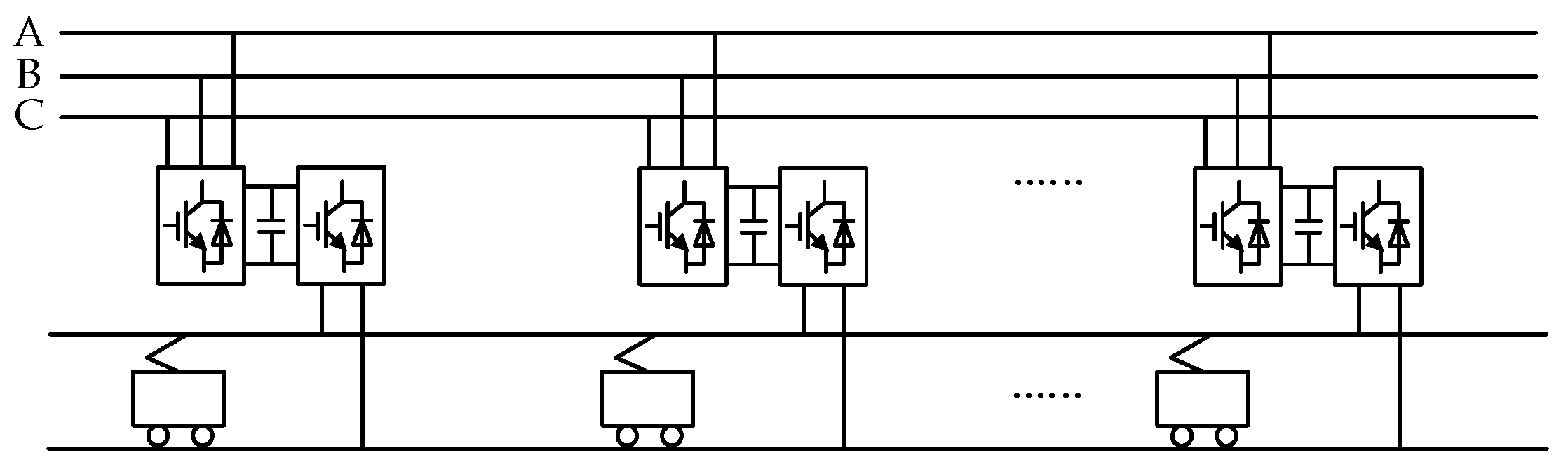
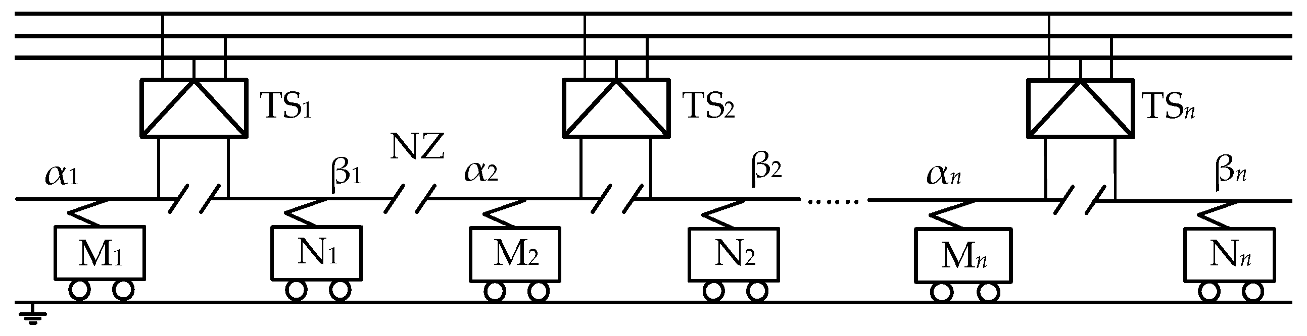
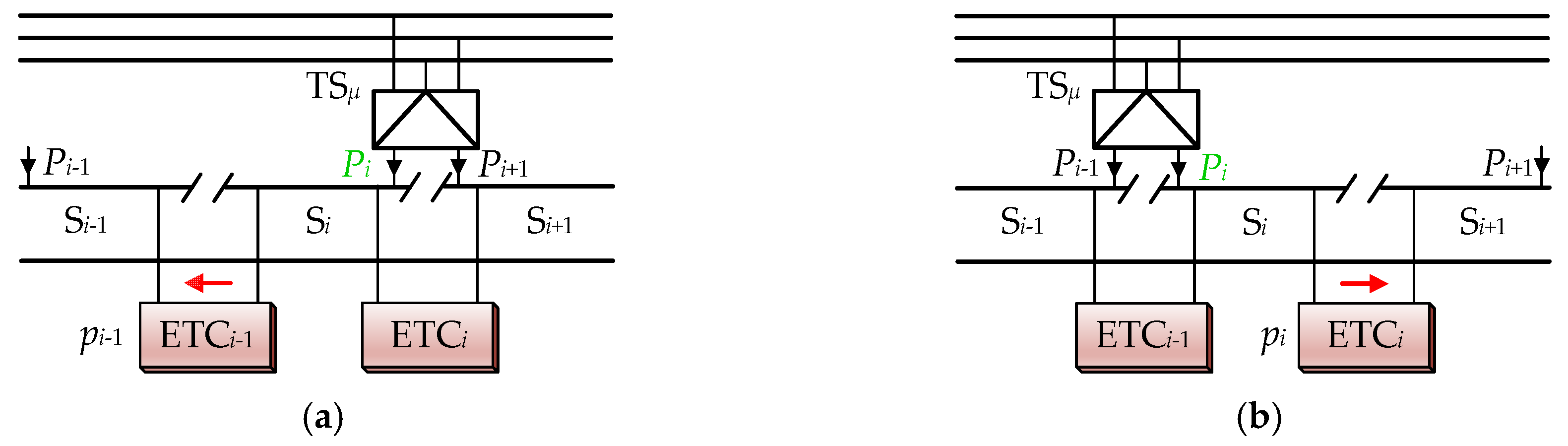
2.2. The Structure and Working Principle of the EMS

The structure and position of the EMS in the traction power supply system are shown in Figure 3. The EMS consists of a central controller and energy transfer converters (ETCs) in parallel on both sides of all NZs. The circuit topology of the ETC is the same as that of the RPC, and both of them are bidirectional AC–DC–AC converters. 2n−1 ETCs are used to connect all power supply sectors in the EMS, which provides the hardware basis for expanding the flow range of the RBE. Pα,n and Pβ,n are separately the power of trains Mn and Nn. p1, p2, …, p2n−1 are the given transmission power of each ETC. The input of the central controller are Pα,1, Pβ,1, …, Pα,n and Pβ,n. The output of the central controller are p1, p2, …, p2n−1. Firstly, Pα,1, Pβ,1, …, Pα,n and Pβ,n are collected and sent simultaneously to the central controller by the odd-numbered ETCs. Secondly, according to the traction power or regenerative braking power of each power supply sector, the central controller uses the algorithm of optimizing the distribution of the regenerative braking power to calculate p1, p2, …, p2n−1. Then, p1, p2, …, p2n−1 are distributed to each converter as their given values. Finally, the controller of each converter completes the closed-loop control of the transmission power. The orderly flow of the RBE is realized and the effective utilization rate of the RBE is improved by the coordinated control of the central controller and ETCs.

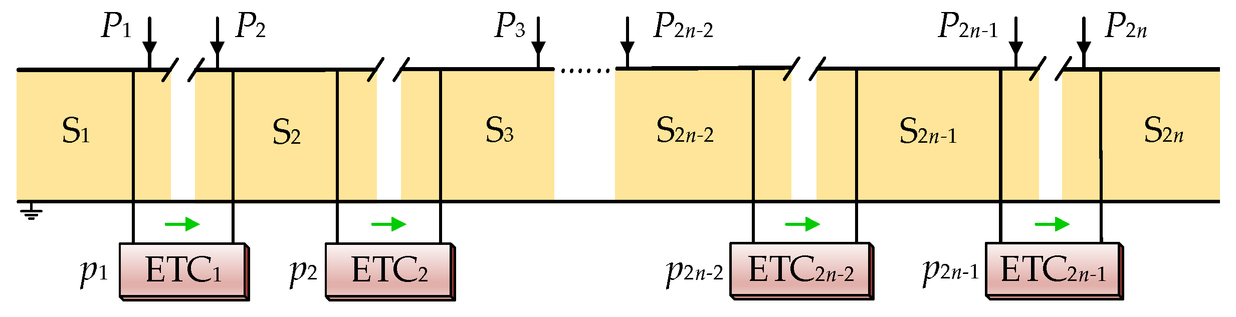
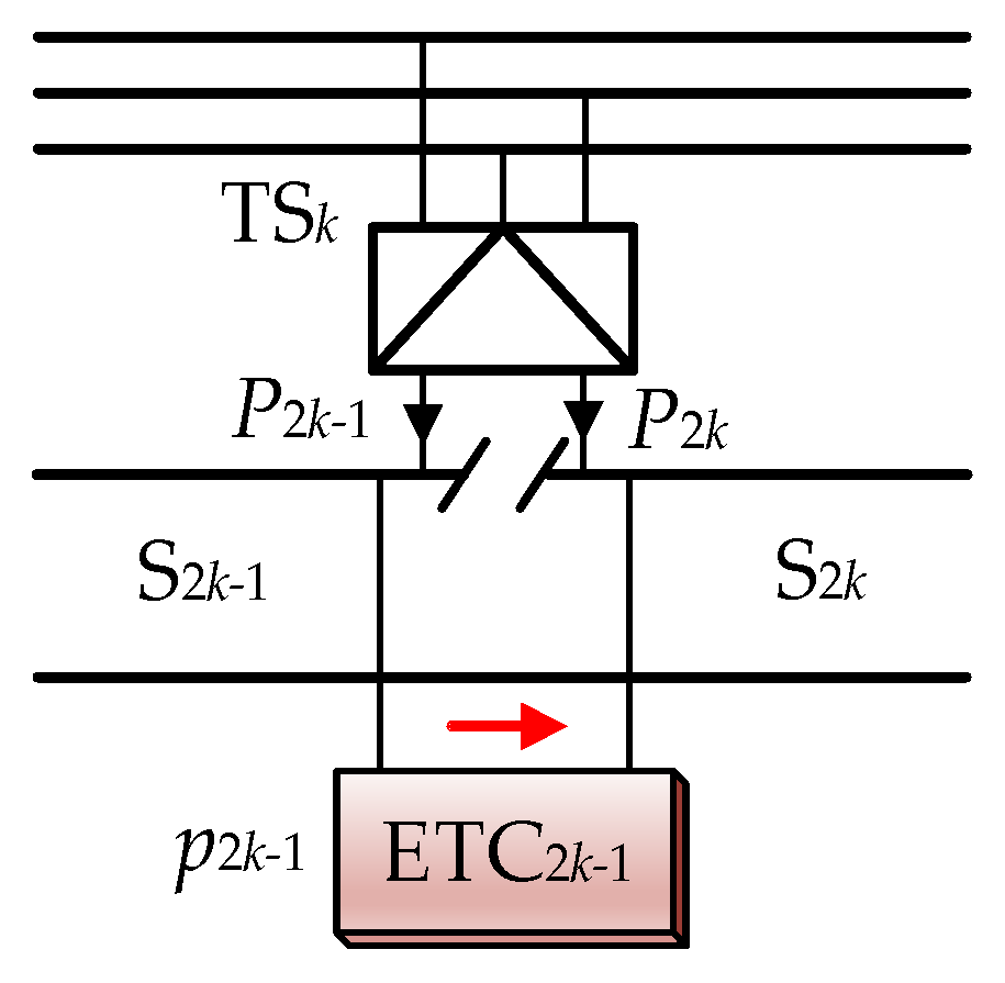
2.3. Controller of the ETC

To realize the closed-loop control of the ETC for transmission power, the control block diagram shown in Figure 4 was adopted. Here, pref was given as the transmission power of the ETC, which was calculated by the algorithm in central controller. The root mean square (RMS) was used to obtain the effective value of the detected signal. PLL represents a phase-locked loop that is used to acquire the synchronous signal of the detection voltage. Since u1 and u2 are the voltages of two adjacent power supply sectors, controlling the AC side current of the ETC is equivalent to controlling its transmission power. The parameter pref is converted to the current given i1_ref, and the current hysteresis comparison method is used to control the AC side current i1 of the left converter. To work properly, converters on both sides must obtain a stable DC side voltage. Therefore, by detecting the voltage udc on the DC side and then adjusting the difference between the voltage udc and its expected value udc_ref, this configuration can be used as the voltage outer loop. The output is multiplied by the synchronous signal of u2; as a given value of i2_ref, in the current inner loop, the AC side current i2 of the right converter is controlled by the method of current hysteresis comparison.
Where, the effective value I1_ref of i1_ref is:
I 1 _ ref = p ref / U 1 .

3. Algorithm of Optimizing the Distribution of the Regenerative Braking Power

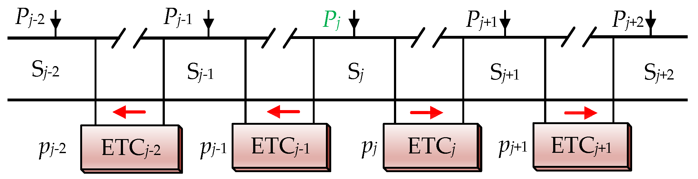
3.1. Algorithm Principle

In the process of optimizing the distribution of the RBE of the whole railway line by the EMS, the loss of the RBE in the circuits and power switching devices is unavoidable. However, whether the RBE flows directly into the utility grid or to the traction trains regulated by the EMS will cause line loss. At the same time, because the AC resistance value per unit length of the catenary is small, the proportion of the line loss is small. For example, the line loss of the RBE in high-speed railway systems accounts for approximately 0.2% [6]. Therefore, the line loss is ignored and the efficiency of the ETC is considered in this paper. If the cascade H-bridge structure is adopted in the ETC, step-down transformers should be added to their input and output sides, the efficiency of the ETC is η = γ·γ1·γ2. Where γ is the efficiency of the bidirectional power electronic converter and γ1 and γ2 are respectively the efficiency of the step-down transformer on the left and right sides. If the MMC structure is adopted, the ETC can be directly connected to the power supply arm without the transformers [29]. Therefore, the efficiency of ETC is η = γ. Regardless of which structure was adopted, the efficiency of each ETC was recorded as η in this paper.
If the RBE is transmitted through multiple ETCs at the same time, the actual utilization rate will be reduced. Therefore, it may be advisable to suppose that the regenerative braking power in each power supply sector can be transmitted by up to ρ ETCs at the same time. Which means the efficiency ηρ of the regenerative braking power transmitted by ρ ETCs is allowed. The regenerative braking power is distributed based on the principle of giving priority to the adjacent power supply sector and maximizing the utilization of the RBE, in order to minimize the loss of converter.
When the regenerative braking power in a certain power supply sector needs to be transferred and the adjacent power supply sectors on both sides are in the state of power consumption, the utilization rate of the RBE can be improved regardless of which side the RBE is transmitted to. However, the unbalanced three-phase current in the TS input side would cause a great threat to the safe operation of the utility grid [12,30,31]. The main reason is the power difference between two power supply sectors in the same TS. Therefore, the RBE is first considered to be transmitted to the power supply sector within the same TS, and the remaining part is then considered to be transmitted to the adjacent power supply sector on the other side.

3.2. Algorithm Steps

According to the above analysis, in order to control all ETCs in EMS to maximize the utilization rate of the RBE, the following algorithm was used to calculate the transmission power of each ETC.
As shown in Figure 5, each power supply sector from left to right is numbered as S1, S2, …, S2n in turn. P1, P2, …, P2n are the feeder power of the power supply sectors in turn. Before EMS regulation, each feeder power is equal to the train power in the corresponding power supply sector. p1, p2, …, p2n−1 are the transmission power of each ETC, and they denotes the active power flowing into ETC from its left port. Therefore, when pl > 0 (l = 1, 2, …, 2n−1), the active power of the right side of the ETCl is −ηpl; when pl < 0, the active power of the right side of the ETCl is − pl/η.
The transmission power p1, p2, …, p2n−1 of each ETC is initialized to 0, and the train power of each power supply sector is assigned to P1, P2, …, P2n correspondingly. When Px > 0 (x = 1, 2, …, 2n), the locomotive uses electricity; when Px < 0, the locomotive regenerates braking.
• Step 1:
According to P1, P2, …, P2n, the power situations of two adjacent power supply sectors in the same TS are evaluated to determine the transmission power of each odd number ETC.
As shown in Figure 6, the red arrow indicates the actual flow direction of the RBE. If the trains in S2k−1 and S2k on both sides of ETC2k−1 (k = 1, 2, …, n) are in traction or regenerative braking conditions, namely, P2k−1P2k > 0, then p2k−1 = 0; if P2k−1P2k < 0, the RBE of one power supply sector should be maximized by another. Therefore, the transmission power of ETC2k−1 can be calculated by:
{ p 2 k 1 = min { P 2 k / η , | P 2 k 1 | } ,   when   P 2 k 1 < 0 ,   P 2 k > 0 p 2 k 1 = η min { P 2 k 1 / η , | P 2 k | } , when P 2 k 1 > 0 ,   P 2 k < 0 .
If the regulation is carried out according to Equation (2), the feeder power of each power supply sector at this time should be written as:
{ P 2 k 1 P 2 k 1 + p 2 k 1 P 2 k { P 2 k p 2 k 1 / η ,   when   P 2 k 1 > 0 ,   P 2 k < 0 P 2 k η p 2 k 1 ,       others ,
where, “P2k−1P2k−1 + p2k−1” represents assigning P2k−1 + p2k−1 to P2k−1.
If the feeder powers P1, P2, …, P2n are all greater than or equal to 0 at this time, the RBE of each power supply sector is effectively utilized. The given values of the transmission power p1, p2, …, p2n−1 of the ETCs were obtained from Equation (2). The algorithm was completed. Otherwise, continue to the next step.
• Step 2:
The power supply sectors corresponding to the items less than 0 in P1, P2, …, P2n at this time were extracted. Whether the RBE of these power supply sectors could be transferred to the adjacent power supply sectors through the even number ETC was evaluated. It may be advisable to assume that there are ξ1 such power supply sectors, and Si (i = 2, 3, …, 2n−1) is one of them.
(1) If i is an odd number, namely, i = 2μ − 1 (μ = 2, 3, …, n):
As shown in Figure 7a, there is Pi+1 ≤ 0 on the premise of implementing step 1. Therefore, the RBE of Si could be used only by traction trains supplied to Si−1 by ETCi−1. The transmission power of ETCi−1 can be calculated by:
p i 1 = η min { | P i | , P i 1 / η } , when P i 1 > 0 .
If the regulation is carried out according to Equation (4), the feeder power of Si−1 and Si at this time should be written as:
{ P i 1 P i 1 + p i 1    P i P i p i 1 / η .
(2) If i is an even number, namely, i = 2μ (μ = 1, 2, …, n):
As shown in Figure 7b, there is also Pi−1 ≤ 0. Therefore, the RBE of Si can only be supplied to the traction trains in Si+1 by ETCi. The transmission power of ETCi can be calculated by:
p i = min { | P i | , P i + 1 / η } , when P i + 1 > 0 .
If the regulation is carried out according to Equation (6), the feeder power of Si and Si+1 at this time should be written as:
{ P i P i + p i P i + 1 P i + 1 η p i .
Each power supply sector corresponding to Px < 0 is processed according to the above method. The transmission powers of the ETCs and the feeder powers at this time were calculated.
If the feeder powers P1, P2, …, P2n are all greater than or equal to 0 at this time, the RBE of each power supply sector is effectively utilized. The given values of the transmission power p1, p2, …, p2n−1 of the ETCs were obtained from Equations (4) and (6). The algorithm was completed. Otherwise, continue to the next step.
• Step 3:
The power supply sectors corresponding to the items less than 0 in P1, P2, …, P2n at this time were extracted. Whether the RBE of these power supply sectors could be transferred to the adjacent power supply sectors by two adjacent ETCs was evaluated. It may be advisable to assume that there are ξ2 such power supply sectors, and Sj (j = 1, 2, …, 2n) is one of them.
(1) If j ≤ 2:
In this case, there is no power supply sector on the left side of Sj, or the feeder powers of the power supply sectors on the left side of Sj are less than or equal to 0. As shown in Figure 8, there was Pj+1 ≤ 0 on the premise of completing step 2. When Pj+2 > 0, in order to make the RBE of Sj be used by the traction trains in Sj+2 as much as possible, the regenerative braking power transferred from Sj was a0 = min{Pj+2/η2, |Pj|}, namely, pj and pj+1 at this time can be calculated by:
{ p j p j + a 0 p j + 1 p j + 1 + η a 0 .
If the regulation is carried out according to Equation (8), the feeder power of Sj and Sj+2 at this time should be written as:
{ P j P j + a 0 P j + 2 P j + 2 η 2 a 0 .
(2) If j ≥ 2n − 1:
In this case, there is no power supply sector on the right side of Sj, or the feeder powers of the power supply sectors on the right side of Sj are less than or equal to 0. As shown in Figure 9, there was also Pj−1 ≤ 0. When Pj−2 > 0, in order to make the RBE of Sj be used by the traction trains in Sj−2 as much as possible, the regenerative braking power transferred from Sj was b0 = min{Pj−2/η2, |Pj|}, namely, pj−1 and pj−2 at this time can be calculated by:
{ p j 1 p j 1 η b 0 p j 2 p j 2 η 2 b 0 .
If the regulation is carried out according to Equation (10), the feeder power of Sj−2 and Sj at this time should be written as:
{ P j 2 P j 2 η 2 b 0    P j P j + b 0 .
(3) If 2 < j < 2n – 1:
As shown in Figure 10, there were also Pj−1 ≤ 0 and Pj+1 ≤ 0. If Pj−2 > 0 and Pj+2 > 0, the regenerative braking power c0 and d0 that need to be transferred from Sj to the left and right sides are respectively written as:
{ c 0 = P j 2 / η 2 , d 0 = P j + 2 / η 2 , when | P j | ( P j 2 + P j + 2 ) / η 2 c 0 = b 0 , d 0 = ε ( | P j | P j 2 / η 2 ) ( | P j | P j 2 / η 2 ) , when | P j | < ( P j 2 + P j + 2 ) / η 2 .
If Pj−2 ≤ 0 and Pj+2 > 0, the RBE of Sj can be transferred to Sj+2 only. At this time, d0 = a0, and c0 = 0.
If Pj−2 > 0 and Pj+2 ≤ 0, the RBE of Sj can be transferred to Sj−2 only. At this time, c0 = b0, and d0 = 0.
Therefore, the transmission powers pj−2, pj−1, pj and pj+1 are respectively written as:
{ p j 1 p j 1 η c 0    p j 2 p j 2 η 2 c 0 p j p j + d 0 p j + 1 p j + 1 + η d 0 .
If the regulation is carried out according to Equation (13), the feeder power of Sj−2, Sj and Sj+2 at this time should be written as:
{ P j 2 P j 2 η 2 c 0    P j P j + c 0 + d 0 P j + 2 P j + 2 η 2 d 0 .
Each power supply sector corresponding to Px < 0 was processed according to the above method. The transmission powers of the ETCs and the feeder powers at this time were calculated.
If the feeder powers P1, P2, …, P2n are all greater than or equal to 0 at this time, the RBE of each power supply sector is effectively utilized. The given values of the transmission power p1, p2, …, p2n−1 of the ETCs were obtained from Equations (8), (10) and (13). The algorithm was completed. Otherwise, continue to the next step.
• STEP δ+1:
If the number of TS is n ≥ (δ + 1)/2, and after step δ (2 < δ < ρ), there are still some items in P1, P2, …, P2n less than 0. These items were extracted and whether the RBE of these power supply sectors could be transmitted to adjacent power supply sectors by adjacent δ ETCs was evaluated. It may be advisable to assume that there are ξδ such power supply sectors, and Sr (r = 1, 2, …, 2n) is one of them.
(1) If r ≤ min{δ, 2nδ}:
In this case, there is no power supply sector on the left side of Sr or the feeder powers of the power supply sectors on the left side of Sr are less than or equal to 0. There are Pr+1 ≤ 0, …, Pr+δ−1 ≤ 0 on the premise of completing step δ. When Pr+δ > 0, in order to make the RBE of Sr be used by the traction trains in Sr+δ as much as possible, the regenerative braking power transferred from Sr is a0 = min{Pr+δ/ηδ, |Pr|}, namely, pr, …, pr+δ−1 at this time can be calculated by:
{ p r p r + a 0 p r + 1 p r + 1 + η a 0 , p r + δ p r + δ + η δ 1 a 0 .
If the regulation is carried out according to Equation (15), the feeder power of Sr and Sr+δ at this time should be written as:
{ P r P r + a 0 P r + δ P r + δ η δ a 0 .
(2) If max{δ, 2nδ} ≤ r ≤ 2n:
In this case, there is no power supply sector on the right side of Sr or the feeder powers of the power supply sectors on the right side of Sr are less than or equal to 0. There are also Pr−1 ≤ 0, …, Prδ+1 ≤ 0. When Prδ > 0, in order to make the RBE of Sr be used by the traction trains in Srδ as much as possible, the regenerative braking power transferred from Sr is b0 = min{Prδ/ηδ, |Pr|}, namely, pr−1, …, prδ+1 at this time can be calculated by:
{ p r 1 p r 1 η b 0 p r 2 p r 2 η 2 b 0 p r δ + 1 p r δ + 1 η δ b 0 .
If the regulation is carried out according to Equation (17), the feeder power of Srδ and Sr at this time should be written as:
{ P r δ P r δ η δ b 0 P r P r + b 0 .
(3) If 2n ≥ 2δ+1 and δ < r < 2nδ+1:
There are also Prδ+1 ≤ 0, …, Pr−1 ≤ 0, Pr+1 ≤ 0, …, Pr+δ−1 ≤ 0. If Prδ > 0 and Pr+δ > 0, the regenerative braking power c0 and d0 that need to be transferred from Sr to the left and right sides are respectively written as:
{ c 0 = P r δ / η δ , d 0 = P r + δ / η δ , when | P r | ( P r δ + P r + δ ) / η δ c 0 = b 0 , d 0 = ε ( | P r | P r δ / η δ ) ( | P r | P r δ / η δ ) , when | P r | < ( P r δ + P r + δ ) / η δ .
If Prδ ≤ 0 and Pr+δ > 0, the RBE of Sr can be transferred to Sr+δ only. At this time, d0 = a0 and c0 = 0.
If Prδ > 0 and Pr+δ ≤ 0, the RBE of Sr can be transferred to Srδ only. At this time, c0 = b0 and d0 = 0.
Therefore, the transmission powers prδ, prδ+1, …, pr+δ−1 of these 2δ ETCs are respectively written as:
{ p r 1 p r 1 η c 0 p r δ p r δ η δ c 0 p r p r + d 0 p r + δ 1 p r + δ 1 + η δ 1 d 0 .
If the regulation is carried out according to Equation (20), the feeder power of Srδ, Sr and Sr+δ at this time should be written as:
{ P r δ P r δ η δ c 0 P r P r + c 0 + d 0 P r + δ P r + δ η δ d 0 .
Each power supply sector corresponding to Px < 0 was processed according to the above method. The transmission powers of ETCs and the feeder powers at this time were calculated.
If the feeder powers P1, P2, …, P2n are all greater than or equal to 0 at this time, the RBE of each power supply sector is effectively utilized. The given values of the transmission power p1, p2, …, p2n−1 of the ETCs were obtained from Equations (15), (17) and (20). The algorithm was completed. Otherwise, continue to the next step.
The algorithm was completed until each Px ≥ 0, namely, there was no RBE in each power supply sector, or the RBE was transferred simultaneously by using the adjacent ρ ETCs (step ρ+1 was completed). After calculating the utilization rate RBE of the whole railway line, the algorithm was completed.
The flowchart of the algorithm is shown in Figure 11.

4. Simulation Validation

In the simulation part, a traction power supply system consisting of four TSs and eight power supply sectors was taken as an example, namely, when n = 4 in Figure 3. ρ was 3, and η was 95%.

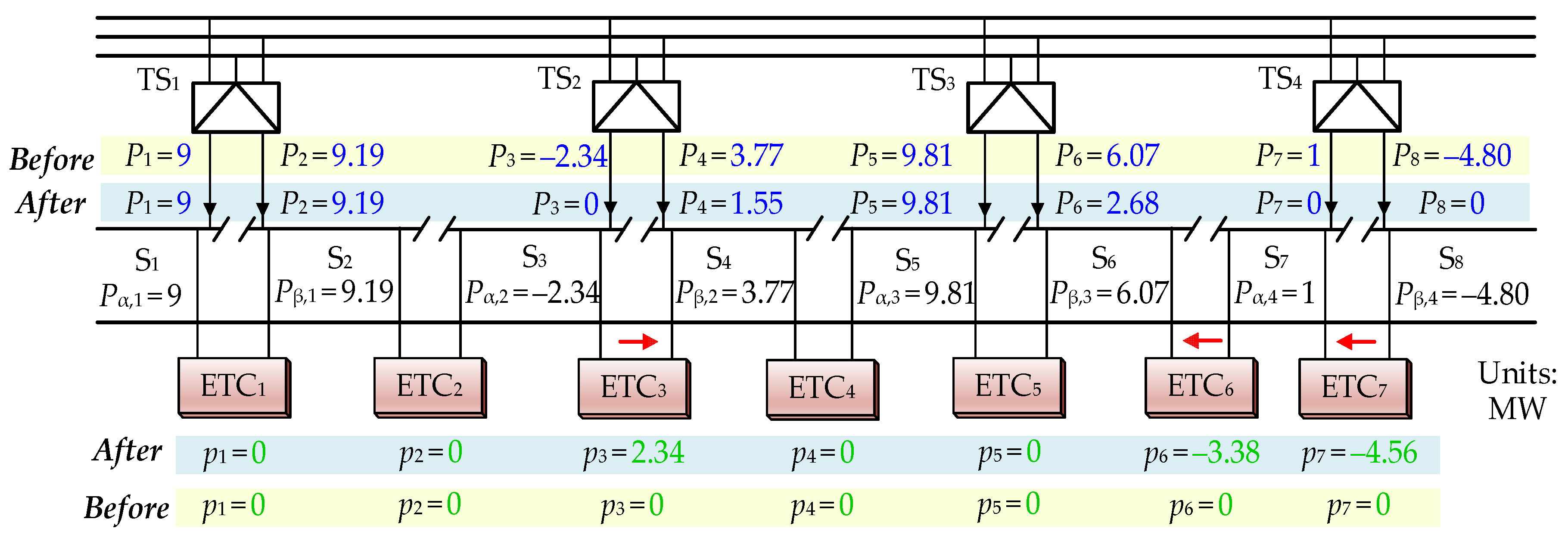
4.1. Algorithm Validation

Three examples were given to verify the algorithm as follows.
(1) Example 1:
Train Power (Pα,1, Pβ,1, …, Pα,4 and Pβ,4) in the traction power supply system at a certain time were separately 9 MW, 9.19 MW, −2.34 MW, 3.77 MW, 9.81 MW, 6.07 MW, 1 MW and −4.8 MW, as shown in Figure 12. The negative sign indicates that the power supply sector feeds back electric energy to the utility grid. Therefore, the total positive power of all trains was 38.84 MW and the total negative power of all trains was –7.14 MW. The feeder power (P1, P2, …, P8) and the transmission power (p1, p2, …, p7) of ETC1-ETC7 before and after optimization by the algorithm are also shown in Figure 12. The negative sign indicates that the transmission power direction of the ETC is from right to left, and the direction of the red arrow is the actual flow direction of the RBE. It should be noted that since multiple trains in the same power supply sector was equated to one, the transmission of the RBE in the same power supply sector did not need to be considered. Since the transmission power of all ETCs was 0 before optimization, the feeder power was equal to the train power before optimization. What is more, the total power provided by the power grid was 32.23 MW, the total power fed back to the power grid was 0.0 MW and the loss power of ETCs was 0.53 MW after optimization. Here, the total power provided by the power grid was the sum of the positive feeder power of eight power supply sectors. The total power fed back to the power grid was the sum of the negative feeder power of eight power supply sectors.
By analyzing the optimization results of the algorithm, the following conclusions could be drawn:
Since no regenerative braking power was transferred to S1, S2 and S5 during the optimization process, the feeder powers P1, P2 and P5 of these power supply sectors were still the corresponding train power. All regenerative braking power in S3 was transferred to S4 by ETC3. Therefore, the optimized feeder power P3 was 0 MW, and P4 was 1.55 MW. All regenerative braking power in S8 was transferred to S7 by ETC7, and part of the regenerative braking power was transferred to S6 by ETC6 after being used by the traction train in S7. Therefore, the optimized feeder power P6 was 2.68 MW, P7 was 0 MW and P8 was 0 MW. After the optimization of the algorithm, the feeder power of each power supply sector was greater than or equal to 0, and the power obtained from the utility grid by S4, S6 and S7 was significantly less than before, i.e., the RBE of the whole railway line was fully utilized. The results show that the proposed algorithm could significantly improve the effective utilization of the RBE.
To fully consider the different states of the power supply system and verify the universality and validity of the algorithm, the following two typical examples are given:
(2) Example 2:
The train powers of the eight power supply sectors were separately 8.45 MW, 2.11 MW, 4.19 MW, −7.65 MW, −1.54 MW, −9.41 MW, 2.11 MW and 7.67 MW. Therefore, the total positive power of all trains was 24.53 MW and the total negative power of all trains was −18.60 MW. The transmission powers of ETC1-ETC7 calculated by the algorithm were separately −0.77 MW, −2.92 MW, −7.27 MW, 0 MW, 1.38 MW, 10.72 MW and 8.07 MW. Then, the feeder powers were separately 7.68 MW, 0 MW, 0 MW, 0 MW, −0.16 MW, 0 MW, 0 MW and 0 MW at this time. Therefore the total power provided by the power grid was 7.68 MW, the total power fed back to the power grid was −0.16 MW, and the loss power of ETCs was 1.75 MW after optimization. Obviously, most of the RBE was utilized by traction trains in other power supply sectors after the optimization of the algorithm. However, there was still some RBE in S5. If the regenerative braking power could be transferred by four ETCs at the same time, this part of the energy could be transferred to S1. At this time, the RBE in the whole system could be fully utilized. Considering that the remaining regenerative braking power was less and the loss was larger when transferring by multiple ETCs, the comprehensive economic and social benefits were not obvious. Therefore, even if the RBE was directly fed back to the utility grid, the impact on the utility grid was not great.
(3) Example 3:
When the train powers of the eight power supply sectors were separately 5.06 MW, 2.31 MW, −6.57 MW, −9.68 MW, 0.7 MW, 4.21 MW, −2.18 MW and 1.09 MW. Therefore, the total positive power of all trains was 13.37 MW and the total negative power of all trains was −18.43 MW. The transmission powers of ETC1–ETC7 calculated by the algorithm were separately −5.06 MW, −7.64 MW, −1.47 MW, 4.31 MW, 3.4 MW, −0.98 MW and 1.15 MW. Then the feeder powers were separately 0 MW, 0 MW, 0 MW, −3.82 MW, 0 MW, 0 MW, 0 MW and 0 MW at this time. Therefore, the total power provided by the power grid was 0.00 MW, the total power fed back to the power grid was −3.82 MW, and the loss power of ETCs was 1.24 MW after optimization. Obviously, after solving the algorithm, there was no power supply sector to obtain electricity from the utility grid, but there was still some RBE in S4. Even if the regenerative braking power could be transferred by more ETCs at the same time, the remaining RBE could not be fully utilized. However, the effective utilization of the RBE was significantly improved, and the final feedback power of S4 to the utility grid was also significantly reduced compared with that before regulation.
The optimization effect of the above three examples is shown in Table 1. Obviously, the total power provided by the power grid and the total power fed back to the power grid were both reduced after optimization. Therefore, the RBE could be effectively utilized by other traction trains after optimization. It shows that the proposed scheme could not only reduce the cost of electricity, but also reduce the impact of the RBE on the public power grid.

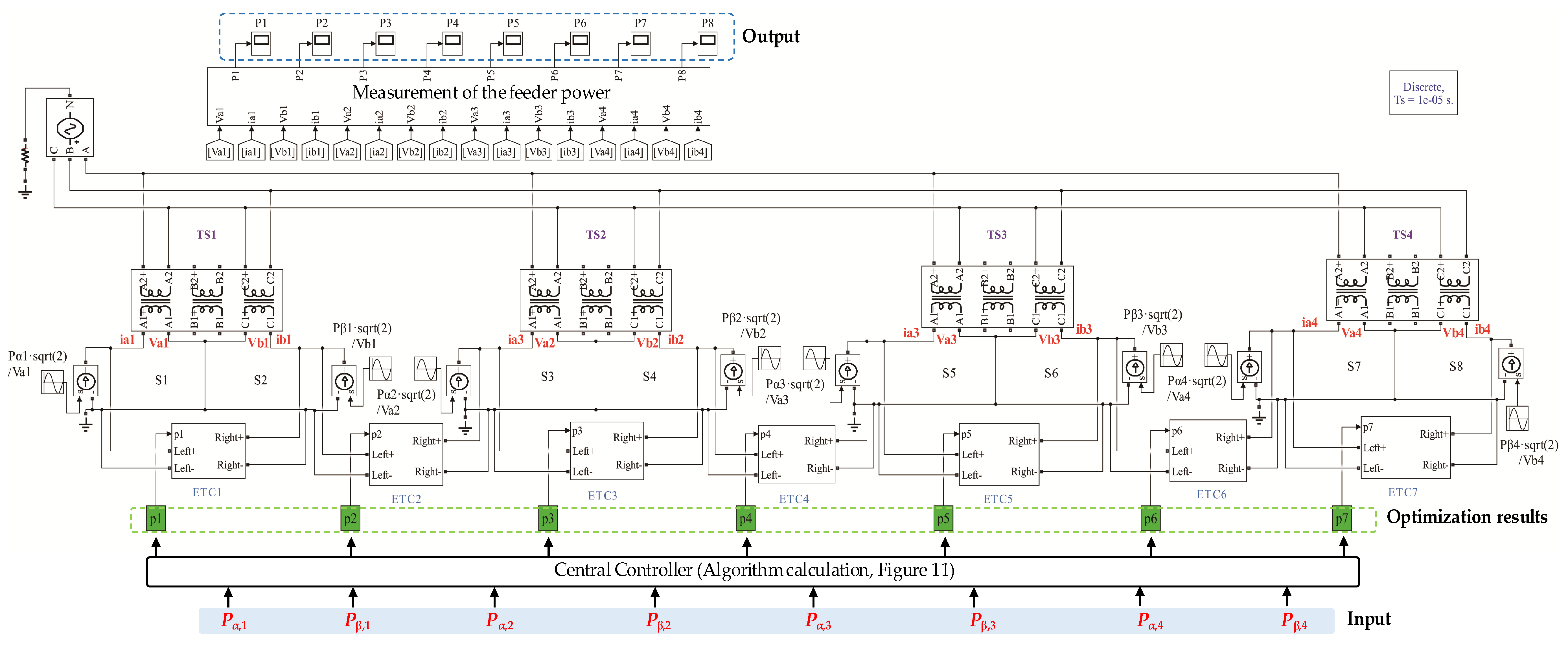
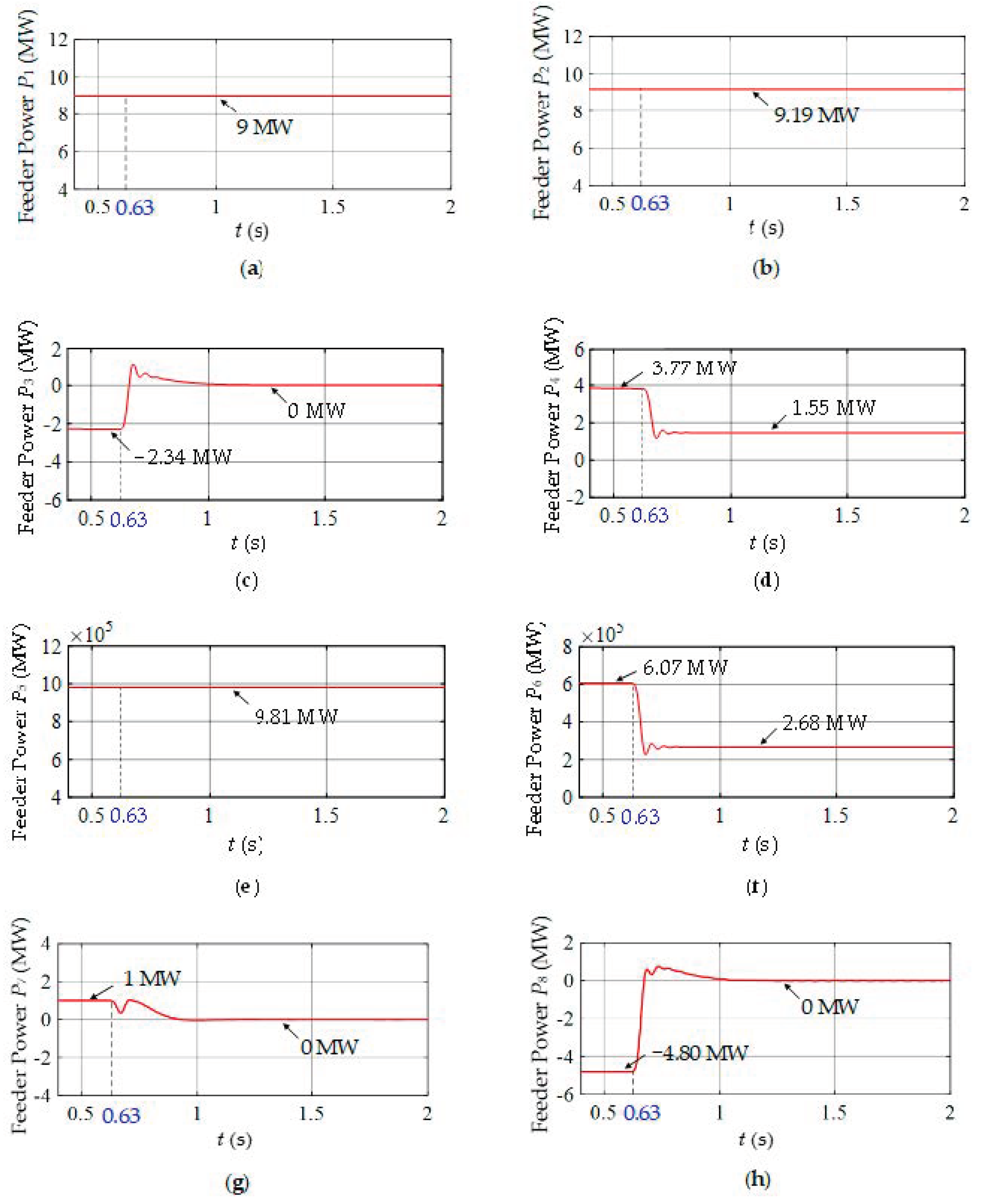
4.2. Simulation Results

To prove the feasibility of the proposed scheme, the Simulink model of this traction power supply system was built, as shown in Figure 13. The train was equivalent to a controllable current source. The input of this model were the train power (Pα,1, Pβ,1, …, Pα,4, and Pβ,4) in Example 1. The parameters of the system in Table 2. The optimization results (p1, p2, …, p6, and p7) of the algorithm were the given power of ETC1–ETC7. The output of this model were the feeder power (P1, P2, …, P8). The total simulation time was 2 s. EMS started to operate at 0.63 s.
The feeder power waveforms of eight power supply sectors before and after the optimization control of the EMS are shown in Figure 14a–h. The feeder power was equal to the train power in the corresponding power supply sector before 0.63 s. After 0.63 s, the EMS began to regulate, and the system entered a steady state at approximately 1 s. According to the transmission power calculated by the algorithm, the RBE was adjusted by eight ETCs. Obviously, the RBE feedback to the utility grid was reduced, and the effective utilization rate of the RBE of the whole railway line was improved. The simulation results verified the feasibility and effectiveness of the proposed scheme.

5. Conclusions

In this paper, an EMS for improving the effective utilization rate of the RBE of the whole railway line and the corresponding algorithm of optimizing the distribution of the regenerative braking power were presented. The central controller used the proposed algorithm to calculate the transmission power of each ETC and distributed them to each ETC synchronously. The ETCs themselves completed the closed-loop control of transmission power, optimized and controlled the RBE generated by all trains, in order to realize the sharing of the RBE in various power supply sectors. Finally, the validity and feasibility of the proposed scheme and algorithm were verified by MATLAB/Simulink experiments. The results show that the effective utilization rate of RBE was improved, the cost of train power consumption was reduced, and the impact of the RBE on the traction power supply system and the utility grid was reduced. The proposed scheme could further improve the existing traction power supply system, and provided a new solution and theoretical guidance for improving the level of energy efficiency management and energy saving effect of the traction power supply system.
In the process of engineering implementation, the EMS proposed in this paper involves not only the centralized control of multiple bidirectional power electronic converters and the design of intelligent optimization algorithms, but also the application of communication technology. This scheme needs to use the existing communication technology to transmit the traction power grid data, which can be completed with the help of the existing communication equipment of the railway system. The communication protocol can also ensure that the central controller processes the power grid data collected by the ETCs at the same time. Therefore, the current communication technology can meet the requirements of the scheme in terms of the communication rate and synchronization of data processing. Since the ETCs are connected in parallel on both sides of the neutral zone, even when the EMS fails, it affects only the function of the EMS itself, and does not affect the power supply function of the original traction power supply system.
Although the ETC connecting two power supply arms in the same TS has the same topology as the existing RPC, the ETC was used only to transmit the RBE, and had the advantages of small device capacity and simple control strategy. If the functions of compensating negative sequences and reactive power, and eliminating harmonics were considered to be added, the additional compensation power could be calculated according to the feeder power of each power supply sector obtained by the algorithm and the control mode of the RPC. Since the main focus of this paper was to realize the sharing of the RBE of the whole railway line and improve the effective utilization of the RBE, there was no analysis of this aspect.

Author Contributions

Conceptualization, Q.L., B.H. and Z.G.; Data curation, J.M., Z.Z. and J.L.; Formal analysis, Q.L., B.H., X.W. and J.M.; Methodology, Q.L., B.H. and Z.G.; Project administration, Q.L.; Writing–original draft, Q.L., B.H., Z.G. and C.C.

Funding

This work was supported by Shenhua Group Co., Ltd. science and technology innovation projects (No: CSIE16024877).

Conflicts of Interest

The authors declare no conflicts of interest.

References

  1. Hayashiya, H.; Yokokawa, S.; Iino, Y.; Kikuchi, S.; Suzuki, T.; Uematsu, S.; Sato, N.; Usui, T. Regenerative energy utilization in a.c. traction power supply system. In Proceedings of the 2016 IEEE International Power Electronics and Motion Control Conference (IPEMC), Hefei, China, 20–22 May 2016; pp. 1125–1130. [Google Scholar]
  2. Song, K.; Georgios, K.; Li, J.; Wu, M.; Vassilios, G.A. High performance control strategy for single-phase three-level neutral-point-clamped traction four-quadrant converters. IET Power Electron. 2017, 11, 884–893. [Google Scholar]
  3. Gazafrudi, S.M.M.; Langerudy, A.T.; Fuchs, E.F.; Al-Haddad, K. Power quality issues in railway electrification: A comprehensive perspective. IEEE Trans. Ind. Electron. 2015, 62, 3081–3090. [Google Scholar] [CrossRef]
  4. He, L.; Xiong, J.; Ouyang, H.; Zhang, P.; Zhang, K. High-performance indirect current control scheme for railway traction four-quadrant converters. IEEE Trans. Ind. Electron. 2014, 61, 6645–6654. [Google Scholar] [CrossRef]
  5. Douglas, H.; Roberts, C.; Hillmansen, S.; Schmid, F. An assessment of available measures to reduce traction energy use in railway networks. Energy Convers. Manag. 2015, 106, 1149–1165. [Google Scholar] [CrossRef]
  6. Ma, F.; Luo, A.; Xu, X.; Xiao, H.; Wu, C.; Wang, W. A simplified power conditioner based on half-bridge converter for high-speed railway system. IEEE Trans. Ind. Electron. 2013, 60, 728–738. [Google Scholar] [CrossRef]
  7. Lu, Q.; He, B.; Wu, M.; Zhang, Z.; Luo, J.; Zhang, Y.; He, R.; Wang, K. Establishment and analysis of energy consumption model of heavy-haul train on large long slope. Energies 2018, 11, 965. [Google Scholar] [CrossRef]
  8. Ma, Q.; Guo, X.; Luo, P.; Zhang, Z. A novel railway power conditioner based on super capacitor energy storage system. Trans. China Electrotech. Soc. 2018, 33, 1208–1218. (In Chinese) [Google Scholar]
  9. Kaleybar, H.J.; Kojabadi, H.M.; Brenna, M.; Foiadelli, F.; Zaninelli, D. An intelligent strategy for regenerative braking energy harvesting in ac electrical railway substation. In Proceedings of the 2017 5th IEEE International Conference on Models and Technologies for Intelligent Transportation Systems (MT-ITS), Naples, Italy, 26–28 June 2017; pp. 391–396. [Google Scholar]
  10. Gonzalez-Gil, A.; Palacin, R.; Batty, P. Sustainable urban rail systems: Strategies and technologies for optimal management of regenerative braking energy. Energy Convers. Manag. 2013, 75, 374–388. [Google Scholar] [CrossRef]
  11. Serrano-Jiménez, D.; Abrahamsson, L.; Castaño-Solís, S.; Sanz-Feito, J. Electrical railway power supply systems: Current situation and future trends. Int. J. Electr. Power Energy Syst. 2017, 92, 181–192. [Google Scholar] [CrossRef]
  12. He, X.; Ren, H.; Lin, J.; Han, P.; Wang, Y.; Peng, X.; Shu, Z. Power flow analysis of the advanced co-phase traction power supply system. Energies 2019, 12, 754. [Google Scholar] [CrossRef]
  13. Mochinaga, Y.; Takeda, M.; Hasuike, K. Static power conditioner using GTO converters for ac electric railway. In Proceedings of the IEEE Conference Record of the Power Conversion Conference, Yokohama, Japan, 19–21 April 1993; pp. 641–646. [Google Scholar]
  14. Li, Q. Power Supply System of Electrified Railway and Its Power Quality Control Technology; China Electric Power Press: Beijing, China, 2015; pp. 140–141. [Google Scholar]
  15. Hayashiya, H.; Kikuchi, S.; Matsuura, K.; Hino, M.; Tojo, M.; Kato, T. Possibility of energy saving by introducing energy conversion and energy storage technologies in traction power supply system. In Proceedings of the 15th IEEE European Conference on Power Electronics and Applications, Lille, France, 2–6 September 2013; pp. 1–8. [Google Scholar]
  16. Wang, Y.; Chen, M.; Lei, G.; Luo, J. Flexible traction power system adopting energy optimisation controller for AC-fed railway. Electron. Lett. 2017, 53, 554–556. [Google Scholar] [CrossRef]
  17. Liu, X.; Li, Q.; Kang, J.; Wei, X. Compensation principle of cophase traction power supply system and its regenerative braking characteristics. Power Syst. Technol. 2010, 34, 99–103. (In Chinese) [Google Scholar]
  18. He, X.; Shu, Z.; Peng, X.; Zhou, Q.; Zhou, Y.; Zhou, Q. Advanced cophase traction power supply system based on three-phase to single-phase converter. IEEE Trans. Power Electron. 2014, 29, 5323–5333. [Google Scholar] [CrossRef]
  19. He, X.; Guo, A.; Peng, X.; Zhou, Y.; Shi, Z.; Shu, Z. A traction three-phase to single-phase cascade converter substation in an advanced traction power supply system. Energies 2015, 8, 9915. [Google Scholar] [CrossRef]
  20. Zhang, Z.; Fickert, L. Power hardware-in-the-loop test of the energy feedback device in urban rail transportation system. In Proceedings of the 19th International Scientific Conference on Electric Power Engineering (EPE), Brno, Czech Republic, 16–18 May 2018. [Google Scholar]
  21. Wu, J.; Wang, X.; Li, L.; Du, Y. Hierarchical control strategy with battery aging consideration for hybrid electric vehicle regenerative braking control. Energy 2018, 145, 301–312. [Google Scholar] [CrossRef]
  22. Li, L.; Wang, X.; Xiong, R.; He, K.; Li, X. AMT downshifting strategy design of HEV during regenerative braking for process for energy conservation. Appl. Energy 2016, 183, 914–925. [Google Scholar] [CrossRef]
  23. Lv, C.; Zhang, J.; Li, Y.; Yuan, Y. Mechanism analysis and evaluation methodology of regenerative braking contribution to energy efficiency improvement of electrified vehicles. Energy Convers. Manag. 2015, 92, 469–482. [Google Scholar] [CrossRef]
  24. Zhao, D.; Chu, L.; Xu, N.; Sun, C.; Xu, Y. Development of a Cooperative Braking System for Front-Wheel Drive Electric Vehicles. Energies 2018, 11, 378. [Google Scholar] [CrossRef]
  25. Li, Q.; Huang, W.; Chen, W.; Yan, Y.; Shang, W.; Li, M. Cascaded Multiport Converter for SRM-Based Hybrid Electrical Vehicle Applications. Int. J. Hydrog. Energy 2019, 44, 5454–5461. [Google Scholar] [CrossRef]
  26. Zhang, Y.; Zhang, X. An Optimized Power-Split Method Based on Fuzzy Logic Control for Fuel Cell-Battery FCHEV Powertrain. In Proceedings of the 4th IEEE Southern Power Electronics Conference (SPEC), Singapore, 10–13 December 2018. [Google Scholar]
  27. Cho, I.; Bae, J.; Park, J.; Lee, J. Experimental Evaluation and Prediction Algorithm Suggestion for Determining SOC of Lithium Polymer Battery in a Parallel Hybrid Electric Vehicle. Appl. Sci. 2018, 8, 1641. [Google Scholar] [CrossRef]
  28. Abrahamsson, L.; Schütte, T.; Östlund, S. Use of converters for feeding of AC railways for all frequencies. Energy Sustain. Dev. 2012, 16, 368–378. [Google Scholar] [CrossRef] [Green Version]
  29. Luo, A.; Ma, F.; Wu, C.; Ding, S.; Zhong, Q.; Shuai, Z. A Dual-Loop Control Strategy of Railway Static Power Regulator Under V/V Electric Traction System. IEEE Trans. Power Electron. 2011, 26, 2079–2091. [Google Scholar] [CrossRef]
  30. Ma, F.; Zhu, Z.; Min, J.; Yue, Y.; He, X. Model Analysis and Sliding Mode Current Controller for Multilevel Railway Power Conditioner for the V/v Traction System. IEEE Trans. Ind. Electron. 2019, 34, 1243–1253. [Google Scholar] [CrossRef]
  31. Canales, J.; Aizpuru, I.; Iraola, U.; Barrena, J.; Barrenetxea, M. Medium-Voltage AC Static Switch Solution to Feed Neutral Section in a High-Speed Railway System. Energies 2018, 11, 2740. [Google Scholar] [CrossRef]
Figure 1. Continuous cophase power supply system.
Energies 12 04166 g001
Figure 2. Sectional powered railway traction system.
Energies 12 04166 g002
Figure 3. Railway power supply system with an energy management system (EMS).
Energies 12 04166 g003
Figure 4. Control block diagram of the energy transfer converter (ETC).
Energies 12 04166 g004
Figure 5. The simplified system and its power description.
Energies 12 04166 g005
Figure 6. ETC2k−1 transfers the regenerative braking power to adjacent power supply sectors in traction substation (TS)k.
Energies 12 04166 g006
Figure 7. The ETC transfers regenerative braking power to the adjacent power supply sector: (a) i is an odd number and (b) i is an even number.
Energies 12 04166 g007
Figure 8. When j ≤ 2, the regenerative braking power is transferred by two adjacent converters: (a) j = 1 and (b) j = 2.
Energies 12 04166 g008
Figure 9. When j ≥ 2n − 1, the regenerative braking power is transferred by two adjacent converters: (a) j = 2n – 1 and (b) j = 2n.
Energies 12 04166 g009
Figure 10. When 2 < j < 2n − 1, the regenerative braking power is transferred by two adjacent converters.
Energies 12 04166 g010
Figure 11. Flowchart of the algorithm.
Energies 12 04166 g011
Figure 12. The feeder power and the transmission power of ETC1–ETC7 before and after optimization by the algorithm.
Energies 12 04166 g012
Figure 13. The Simulink model of the traction power supply system.
Energies 12 04166 g013
Figure 14. Feeder power waveforms of the eight power supply sectors before and after EMS optimal regulation: (a) S1; (b) S2; (c) S3; (d) S4; (e) S5; (f) S6; (g) S7 and (h) S8.
Energies 12 04166 g014
Table 1. The optimization effect of the above three examples.
ExampleTotal Power of Trains (MW)Total Power (MW) (Before Optimization)Total Power (MW; After Optimization)
PositiveNegativeProvided by the Power GridFed Back to the Power GridProvided by the Power GridFed Back to the Power GridLoss in ETCs
138.84−7.1438.84−7.1432.230.000.53
224.53−18.6024.53−18.607.68−0.161.75
313.37−18.4313.37−18.430.00−3.821.24
It should be pointed out that the algorithm cannot improve the effective utilization rate of the RBE when all trains in the power supply sectors are in a traction or regenerative braking state. In this case, the transmission power of ETC1–ETC7 calculated by the algorithm is 0.
Table 2. Parameters of the system.
ParametersValue
Three-phase voltage110 kV
Frequency50 Hz
Variable Ratio of the TS110:25
Variable Ratio of the Step-down Transformer25:2
AC side output inductance5 mH
AC side output resistance12 mΩ
DC side capacitor20 mF
DC side reference voltage3 kV

