1. Introduction
The demand for heat for heating purposes and preparation of domestic hot water is to a significant extent covered by the use of installations which burn gaseous and liquid fuels. A significant part of these systems in the EU [
1], and most of them in Poland [
2], are extremely worn-out. They are not efficient and produce considerable amounts of impurities and pollutants which have a negative effect on the environment [
3]. In his publication [
4], Lombardi stated that the existing technologies related to heat recovery from waste treatment technological systems do not implement any solutions related to the removal of pollution from exhaust gases, but only the recovery of heat from waste. In addition, heat recovery efficiency remains at relatively low levels. In the review of solutions for technological systems of heat sources made in the publication [
5], Barma described the applied methods of heat recovery, including from exhaust gases. However, he did not describe a technological system that, in addition to being a recuperator, would also make the removal of pollutants from exhaust gases possible. The author additionally stated in the publication that, in addition to the use of typical recuperator solutions, other solutions should also be sought, e.g., to increase the temperature of combustion substrates, as well as to recover heat of condensation. Barma did not indicate specific solutions to this problem. The device implementing such processes has been proposed by the authors of this publication. There are many solutions available on the market that are intended for recovering heat from combustion gases. However, these solution are frequently characterized by small energy efficiency. They only function as heat exchangers. They do not reduce emission of pollutants generated by technological systems of heat sources. They include various types of recuperators, i.e., heat exchangers, which recover waste heat, for example from combustion gases. Solutions with recuperators can include devices installed as separate elements of the technological system of the heat source or devices which constitute an integral part of the combustion chamber, e.g., in condensing boilers. In his publication [
6], Blanco described an interesting heating solution that allows the heating of air supplied to the combustion chamber. However, the main purpose of the described device is to analyze the impact of acid dew point temperature (ADT) on the operation of a boiler powered by different types of fuel. The author did not refer to the increase of boiler efficiency, let alone to the reduction of the amount of emitted flue gas. In their publication [
7], Yang et al. focused on a new heat recuperator solution that aims to recover heat from exhaust gases. The interesting solution proposed by the authors of [
7] is radically different from the device developed by the authors of this manuscript, mainly in the scope of additional possibilities of purifying exhaust gas, as well as water recovery from exhaust gas. The power ranges of the energy sources for which both devices are dedicated are significantly different. Similar solutions to Yang’s, but dedicated to smaller heat sources, were proposed by Liu [
8] and Chen [
9].
Recently, systems with compressor or sorption heat pumps for the recovery and reuse of waste heat have been used most frequently. In their publications, Zhu [
10] and Qu [
11] proposed a completely different approach to the issue of heat recovery from boiler flue gas. They used absorption heat pumps for this purpose. These are completely different solutions from the device proposed by the authors of this manuscript. The coefficient of efficiency of heat recovery, the lack of the possibility of simultaneous flue gas cleaning, and high market prices of sorption heat pumps cause that their use as devices improving the efficiency of heat sources remains debatable. An interesting concept of using an adsorption heat pump for reusing the heat generated by a district heating system in the summer period, when the heat is treated as waste heat, was discussed by Ziembicki et al. [
12]. However, the solutions for heat recovery with the use of recuperators and/or heat pumps do not in any way affect changes in the combustion gas composition, thus they do not contribute to the reduction of environmental burden caused by heat sources. This is a serious disadvantage of these solutions in comparison to the installation described herein, which enhances energy efficiency of boilers and reduces emission of pollutants and impurities, including solid impurities.
Methods of improving control systems in heating boilers are also often applied in order to enhance energy efficiency of heat sources. In his work [
13], Suntivarakorn presented a method of controlling the amount of fuel supplied to the combustion chamber by means of fuzzy control algorithms. The proposed solution allowed increasing the boiler efficiency by 4.34%. Most often, they consist in improving combustion quality by controlling the air-to-fuel ratio. In contrast to the device described herein, these methods do not bring about a considerable reduction in pollutant emissions. Moreover, artificial neural networks, which are often implemented in controllers, need learning processes based on complex algorithms as well as learning data. This has a negative effect on the costs and time required for the modernization of control systems. Analyses of the use of genetic algorithms, artificial neural networks and deep learning methods were presented by Pan [
14], Chen [
15] and Cheng [
16].
Combustion of oils in boilers is possible when the oils are converted to gaseous state and heated to ignition temperature. The main factors which affect the combustion process and emission of the resultant pollutants are: the composition of the fuel (hydrocarbon composition, the content of sulfur, incombustible minerals and solid impurities, and the content and type of fuel oil conditioners and modifiers) and the construction of the burner and combustion chamber. The advancement in the construction of boilers and burners has affected significantly a reduction in emission of pollutants; however, the emission of soot and unburned hydrocarbons mostly during the start-up and shut-down of a boiler remains a problem. At the time of start-up and shut-down, 50–70 of soot is generated with adsorbed products of the polymerization of hydrocarbons and unburned hydrocarbons [
17]. Combustion of poor quality fuel oils, e.g., light oil with an addition of heavy oil, constitutes another problem.
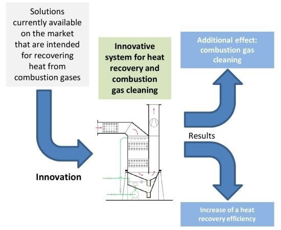
Based on extensive literature review in the field of the already existing solutions for heat recovery and exhaust gas purification, it was found that currently there are no market solutions that would simultaneously carry out these two tasks in the way proposed in the developed system. Technical systems which are intended only for heat recovery are relatively widespread. It should be emphasized that the developed system is significantly different from solutions available on the market, as well as from those that are currently in the research phase and whose preliminary operational results are described in the available scientific publications. This difference mainly concerns simultaneous heat recovery and flue gas cleaning, as well as increased efficiency of heat recovery.
Heavy fuel oils have a greater content of sulfur and other mineral substances, which in the process of combustion create together with water vapor aggressive compounds that have a corrosive impact on the combustion chamber (low-temperature corrosion). Moreover, they pollute the natural environment much more. In the combustion process, the compounds of iron, calcium, sodium and vanadium contained in the oil produce oxides, which at high temperature cause high-temperature corrosion. The content of high-molecular organic compounds, including heavy paraffin and tar compounds, is increased in contaminated light oil. In chambers which are not adjusted for such an oil, its combustion causes enhanced emission of soot and unburned hydrocarbons.
The requirements concerning pollutant emission to the atmosphere, those already in force as well as planned, make it necessary to use not only fuels of appropriate quality and more and more efficient construction of devices, but also necessitate development of solutions for combustion gas cleaning.
To characterize the developed solution in detail, this publication is divided into four sections. In the Introduction, a detailed overview of the current state of relevant knowledge is presented. Innovative aspects of the solution proposed by the authors are also presented, which constitute progress in the analyzed field and at the same time significantly differ in favor of the developed system as compared to those currently operating on the market and being put to tests by other authors. In
Section 2, the authors present technical specifications of the proposed system. They describe the structure and the functioning of the device, as well as detailed diagrams of the system. The initial paragraphs of this section feature some literature references to solutions and methods that were used during the research, which were significantly improved in the developed system.
Section 3 describes the results of theoretical analyses of the developed solution and is partly based on selected measurements from the previous version of the solution.
Section 4 contains conclusions regarding research and analysis of the developed system, as well as plans for its potential development and further research and testing.
3. Results and Discussion
An efficient way of using fuel consists in restricting the emission of waste energy and reducing its adverse environmental effects. The above-mentioned objectives can be achieved by means of introducing specific changes in the construction of devices and by optimizing their performance. The most important activities pertaining to optimization of the performance include control of the air–fuel ratio and selection of its proper values. Stoichiometry of the combustion process was analyzed extensively by J.Szargut [
34]. The correctness of the combustion process can be checked by measuring the composition of combustion gases. To this aim, we should measure CO
2, O
2, CO and H
2O content in the wet combustion gases. The following relation holds for the content of the
ith component in the dry and wet combustion gases:
where
are the content of the
ith component in the wet and dry combustion gases.
X is the content of H
2O in the wet combustion gases—the so-called moisture level of combustion gases. It should be borne in mind that the content of combustion gas components is always determined or measured with a certain error. On the basis of the generalized Ostwald triangle, the intended composition can be adjusted [
34]. The adjustment consists in correcting the measured contents of combustion gas components (mainly oxygen and carbon dioxide) in such a way that, using the smallest possible correction, they would satisfy the conditions which follow from the stoichiometry of the combustion process. The adjusted content of carbon dioxide [CO
2]ad and oxygen [O
2]ad may be calculated by using the formulae:
and
where [O
2], [CO
2], and [CO] are the content of oxygen, carbon dioxide and carbon monoxide before adjustment, respectively; [O
2]ad and [CO
2]ad are the content of oxygen and carbon dioxide after adjustment, respectively; and
and
are the maximum theoretical content of [CO
2] and [CO] in the dry combustion gases, respectively—the coefficient depends on the type of fuel. Usually, contents of [CO
2] and [CO] are not adjusted. All values used in Equations (
2), (
3), (
4), (
5) and (
6) are absolute values. The content of [H
2O] in wet combustion gases is used to recalculate the content of components in wet combustion gases into an analogical content in dry combustion gases (Equation (
1)). Then, the problem with determining [H
2O] does not occur. When some probes for measuring combustion gas components are used, the results can be directly related to dry combustion gases. Calculations were made for light fuel oil in order to determine the impact of uncertainty of [H
2O] determination on the uncertainty of the air–fuel ratio
determination. When the uncertainty of [H
2O] determination is changed by 6%, the uncertainty of
is 0.5%. This justifies the simplifications made by the authors, which consist in not adjusting the measured values of [CO] and [H
2O]. The values of maximum contents of
and
are given in
Table 1 [
36].
and
are dimensionless quantities.
In a general case, the air–fuel ratio is determined from the balance of the following elements after a prior determination of the theoretical air demand: C, H, O, and N. In the case of combustion of fuels containing little nitrogen and when at the same time there is no free carbon in solid combustion products, the following formula can be used to determine the air–fuel ratio
[
34]:
The above relation is particularly suitable, because it does not require knowledge of fuel composition. When the combustion chamber is supplied with fuel oil or natural gas, it is recommended to keep 1.1–1.2. A favorable and effective manner to enhance the energy, ecological and economic efficiency of the combustion chamber is to heat the substrates of combustion (air and/or fuel) with the heat which is recovered through recuperation. Recuperation brings additional energy to the chamber and increases the temperature of fuel combustion. This makes it possible, among other things:
to intensify the use of combustion gases in the chamber;
to save fuel;
to obtain a higher content of H2O in combustion gases (e.g., in driers) and CO2 (in technological processes); and
to lower the temperature of combustion gases discharged to the environment.
Fuel savings due to recuperation is defined by the index [
37]:
where
is fuel savings;
is fuel consumption without recuperation;
is fuel calorific value;
S is heat capacity of combustion gases per fuel unit;
is heat of recuperation in relation to fuel unit;
is difference between the temperature of combustion gases flowing out of the chamber without a recuperator and the ambient temperature; and
is index of temperature distribution.
where
A and
B are air and fuel heat capacity per fuel unit, respectively.
and
are difference between the temperature of heated air and fuel and the ambient temperature, respectively.
and
are expressed in commonly used fuel units.
and
are expressed in KJ/fuel unit.
A,
B, and
S are expressed in KJ/(fuel unit · K).
and
are dimensionless quantities.
,
, and
are expressed in K. It is recommended to adopt the indices of temperature distribution in the combustion chamber in the following ranges [
38]:
for a one-zone chamber 1–1.15;
for a counter-current flow of combustion gases and heated medium in the chamber 1.1–1.3; and
for a multi-zone chamber 1.3–1.5.
After the combustion gases are cooled below the dew point, the water vapor contained in them is successively condensed. Condensation brings about an intensive heat transfer to the condensing agent. The water droplets which appear not only absorb gaseous impurities contained in combustion gases, but also remove solid impurities from them. The process of water vapor condensation in combustion gases should be treated as particularly favorable for making use of combustion gas waste heat and combustion gas cleaning.
The research did not include the recovery and reuse of condensed water from flue gases. This is an issue that should be considered in future research.
The proposed solution is associated with increased capital expenditures and higher operating costs compared to classic (familiar) solutions. The increase in the above costs will, according to estimated analyses, be offset by the positive effects associated with fuel economy and the qualitative and quantitative improvement of pollutant emissions. An estimated analysis of simple payback time for the development and implementation of the solution was carried out. As mentioned above, for financial reasons, no prototype of the installation described in the publication was built. However, a similar construction had been built (the previous version of the device) and, based on the analysis of this solution, simple payback time was estimated. The cost of installation of a similar design (in the previous version of the device) for a 160 kW boiler amounted to approximately 7100 Euro. According to the operational data on the average boiler load operating in the system ( 120 kW), its operation time per year, reduction in oil consumption (compared to the boiler without the device) and fuel cost, simple payback time was estimated. It was 2.6 years for the analyzed parameters.
The results of theoretical analyses of the developed solution, as well as the analyses of selected operating results of the previous version of the system are extremely encouraging. Especially in the areas of increased efficiency of heat recovery, as well as within the aspect of ecological benefits consisting in the reduction of pollutants emitted to the atmosphere. The developed system can be particularly useful for small and medium energy sources, as an element of their technological systems which significantly improves the economic effects of heat production, while reducing its burden on the environment. This is particularly important in the context of adverse climate change of anthropogenic origin. To optimize the production costs of the device, future research should be carried out, which would take into account modern materials devoid of expensive stainless steel and would also reduce the dimensions of the device. In addition, tests should be carried out that will make it possible to extend the functionality of the device in order to recover water condensed from exhaust gases, which can further significantly increase the economic efficiency of the developed device. Conditions that will allow the system to be introduced on the market constitute an extremely important aspect that should be considered in subsequent work on the system. In particular, precise specifications of cost framework for the production of the device, including various power ranges of the heat source (boilers) with which the system will function optimally from the point of view of economic and ecological efficiency.
4. Conclusions
An efficient use of fuel requires control of the air-to-fuel ratio and selection of its optimal values. Heating up the substrates of combustion in the process of recuperation and condensation brings additional energy to the combustion chamber and results in increasing the temperature of combustion gases in the combustion chamber. This in turn enhances the efficiency of the process. In addition, condensation of the water vapor contained in combustion gases reduces the emission of substances harmful to the environment, mainly by washing out solid impurities.
The invention presented herein is comprised of an installation that uses combustion gases for heating combustion substrates, recovers heat by condensing water vapor contained in combustion gases and cleans them in the process of absorption and removal of solid impurities. Liquid or gaseous fuel and air are heated in membrane heat exchangers that fill up the absorption column acting also as a washer, in which gaseous and solid impurities are absorbed and removed by water. Air and/or fuel is additionally heated in an exchanger placed at the combustion gas inlet to the installation. The solution is characterized by a simple construction and a high energy efficiency. In addition, it can be modified for individual needs for fuel and air heating by using multi-section exchangers and two-stage heating of combustion substrates.
The development of the device described in the paper is a consequence of earlier tests and research work on a solution based on identical assumptions and theoretical fundamentals; however, the device under consideration here was built using a slightly different construction (technology). The results of the tests proved to be so promising that the Board of Euro-Box commissioned development of a new generation of the device. The company intended to install the device on other production floors and considered its prospective distribution on a commercial basis. An application under the Regional Operational Programme in the Lubuskie administrative province was filed for financial aid for testing the device which was developed and its implementation. Financial analyses, including the concept of implementation and commercialization, also proved to be extremely promising. This means that there is a great potential for implementing the device (of various sizes and power). The prospects look bright, especially when we take into account the current state of industrial enterprises in Poland, where quite frequently, due to their location (lack of gas networks), worn-out liquid fuel boilers and/or devices supplied with biogas are still in operation.


