Article

A Study on the Performance of a Cascade Heat Pump for Generating Hot Water

1
Graduate School of Mechanical Engineering, Hanbat National University, Daejeon 34158, Korea
2
Department of Mechanical Engineering, Hanbat National University, Daejeon 34158, Korea
*
Author to whom correspondence should be addressed.
Energies 2019, 12(22), 4313; https://doi.org/10.3390/en12224313
Submission received: 3 October 2019 / Revised: 29 October 2019 / Accepted: 9 November 2019 / Published: 12 November 2019

Abstract

:
The use of cascade heat pumps for hot water generation has gained much attention in recent times. The big question that has attracted much research interest is how to enhance the performance and energy saving potential of these cascade heat pumps. This study therefore proposed a new cycle to enhance performance of the cascade heat pump by adopting an auxiliary heat exchanger (AHX) in desuperheater, heater and parallel positions at the low stage (LS) side. The new cascade cycle with AHX in desuperheater position was found to have better performance than that with AHX at heater and parallel positions. Compared to the conventional cycle, heating capacity and coefficient of performance (COP) of the new cascade cycle with AHX in desuperheater position increased up to 7.4% and 14.9% respectively.

1. Introduction

The application of boilers and electric heaters in space heating and hot water generation for domestic and industrial use is expensive, energy intensive and mostly poses a major threat to the climate and environment. The low environmental impacts of heat pumps, coupled with the efficient and cost-effective manner with which they provide heating and hot water makes them popular for domestic and industrial applications [1].
Air source heat pumps operate at lower outdoor temperatures in winter and higher outdoor temperatures in summer seasons. These operating conditions decrease the performance of heat pumps by increasing their irreversibility during compression and decreasing the refrigerant mass flow rate [2]. Moreover, most domestic and industrial applications require hot water temperatures above 60 ° C . Heat pumps used in such applications operate between very low evaporating and higher condensing temperatures, resulting in higher temperature lifts and pressure ratios beyond the applicable limits of single stage heat pumps. Such harsh operating conditions make single-stage heat pumps inefficient and expose compressors to higher discharge temperatures and damage.
Cascade heat pumps operate as two single stage cycles coupled together by a cascade heat exchanger. This makes them advantageous over single stage heat pumps in terms of energy savings, stable water heating and higher hot water temperature generation [3,4]. However, at lower heat source temperatures and higher building loads, the performance of cascade heat pumps deteriorates. Kim and Kim [5] investigated the effect of higher indoor heat exchanger entering water temperature (EWT) and lower ambient temperature on the performance of an air-to-water cascade heat pump and found that hot water temperature, heating capacity and COP decrease with lower ambient temperature and higher indoor heat exchanger EWT. Jung et al. [4] found that the performance of cascade multi-functional heat pumps decreased with an increase in EWT to the condenser of the high stage (HS) cycle. These results reveal the need for a technology that can enhance the performance of cascade heat pumps at such operating conditions to meet the required heating load.
Most research on cascade heat pump cycles have focused on generation of lower temperatures for refrigeration purposes [6,7,8,9,10]. In recent times, hot water generation using cascade heat pumps has become important for domestic and industrial applications, and has generated much research interest. Jung et al. [4] used cascade multi-functional heat pump to produce hot water. Kim and Kim [5] performed an experimental study to investigate water temperature lift and its effect on cascade heat pump performance. Wu et al. [11] experimented with the transient and dynamic behavior of cascade heat pump water heater with phase change material. The cascade heat pump water heater generated an average hot water temperature of 55 ° C . Park et al. [12] conducted an experimental study to investigate performance of a cascade heat pump generating hot water up to a temperature of 60   ° C . Kim et al. [13] investigated the optimal intermediate temperature of a cascade heat pump used for hot water generation. Nenkaew and Tangthien [14] conducted an experimental study on the transient performance of cascade heat pump used for cooling, refrigeration, heating and hot water generation. Soltani et al. [15] compared the performance of single stage and hydronic cascade heat pumps for generating hot water. Tarrad [16] examined a methodology to generate hot water in a cascade heat pump using low temperature heat source. Qu et al. [17] proposed a control algorithm for an air source cascade heat pump used for hot water generation. Ma et al. [18] analyzed the performance of a high temperature cascade heat pump that used a new near-zeotropic refrigerant to produce hot water.
The design of energy efficient cascade heat pumps has become essential, resulting in much research into performance enhancement methodologies through the optimization and control of cascade heat pumps [19]. This study contributes to the design of performance enhancing and energy saving cascade heat pumps by proposing a new cascade heat pump cycle that adopts auxiliary heat exchanger for hot water generation.

2. Experimental Setup and Test Procedure

The experimental setup was designed to investigate performance enhancement and energy saving potential of a new water-to-water cascade heat pump unit. The new cascade cycle is a conventional cascade cycle equipped with an auxiliary heat exchanger at the low stage. Figure 1 is a schematic diagram of the water-to-water cascade heat pump used in this study. Continuous lines represent refrigerant and secondary fluid lines of the conventional system, while dotted lines represent refrigerant lines for operating the AHX. The conventional cascade cycle consisted of two separate cycles, called low stage (LS) and high stage cycles (HS), interconnected by a cascade heat exchanger. Each of the two cycles consisted of a scroll compressor, an electronic expansion valve (EEV), condenser and evaporator. The cascade heat exchanger acted as condenser to the LS cycle and evaporator to the HS cycle. The LS evaporator acted as outdoor heat exchanger (OD HX) while condenser of the HS cycle acted as indoor heat exchanger (ID HX). The new cascade cycle consisted of the conventional cycle with AHX installed in the LS side. The AHX was installed to operate in three different positions so as to determine the position that best enhances performance of the cascade heat pump. Refrigerants R410A and R134a were used for the LS and HS cycles respectively. Specifications of the components of the water-to-water cascade heat pump unit are shown in Table 1.
The cascade heat pump also had two closed loop secondary fluid flow paths for the ID HX and OD HX. Secondary fluid flow loops were simulated using constant temperature baths with brine of 40% ethylene glycol concentration as secondary fluid. Flow rate of the secondary fluid was controlled using an inverter driven pump and a manual needle valve.
During operation of the conventional cascade heat pump, LS refrigerant is compressed into high temperature and pressure refrigerant which gets condensed by the HS refrigerant in the cascade heat exchanger. The condensed refrigerant is expanded by the LS EEV into low temperature and pressure refrigerant which vaporizes in the OD HX by absorbing heat from the outdoor side secondary fluid. Refrigerant vapor from the OD HX then enters the compressor to be compressed into high pressure and temperature refrigerant for the cycle to continue. In the HS cycle, refrigerant R134a vaporizes in the cascade heat exchanger and gets compressed by the high stage compressor. The compressed refrigerant is condensed by secondary fluid in the ID HX, which then goes through the HS EEV and back to the cascade heat exchanger for continuation of the cycle.
To enhance performance and energy saving potential of the cascade heat pump, new cycle was developed by adopting auxiliary heat exchanger (AHX) at the LS side of the conventional cycle to decrease irreversibility of the ID HX. The AHX was placed at three different positions to operate as desuperheater, heater or in parallel with the cascade heat exchanger in order to determine the position that yields the highest system performance.
Figure 2 shows schematic diagram of the cascade heat pump with AHX operating as desuperheater. Continuous lines depict refrigerant and secondary fluid lines in operation, while dotted lines depict closed refrigerant and secondary fluid lines. In desuperheater position, AHX is located between the LS compressor and cascade heat exchanger. When in operation, compressed high temperature LS refrigerant enters the AHX and exchanges heat with secondary fluid from the indoor side constant temperature water bath in the AHX. Low stage refrigerant from the AHX enters the cascade heat exchanger, after which it assumes a similar flow path as that of the conventional cascade heat pump. Secondary fluid from the AHX also enters the ID HX for heat exchange with the HS refrigerant.
In the heater position, AHX is placed between the cascade heat exchanger and LS EEV as shown in Figure 3. Heat exchange in the AHX is therefore between subcooled LS refrigerant from the cascade heat exchanger and secondary fluid from indoor side constant temperature water bath. Figure 4 shows cascade heat pump with AHX in parallel with the cascade heat exchanger. In this position, refrigerant from the LS compressor divides into two flow paths; one flow path goes through the cascade heat exchanger for heat transfer to the HS cycle, while the other flow path goes through the AHX for heat exchange with secondary fluid from the indoor side constant temperature water bath. The two flow paths combine into one, after each flow has been expanded by their respective EEVs, before proceeding to the OD HX and compressor for the cycle to continue.
Experiment was conducted in two phases: firstly, to determine the AHX position that best enhances performance of the cascade heat pump and secondly, to compare performance of the new cycle with the best AHX position with that of the conventional cascade heat pump cycle. Reference indoor entering water temperature (ID EWT) and outdoor entering water temperature (OD EWT) conditions were selected as 55 ° C and 5 ° C respectively, according to ISO 13256-2 [20]. Experiments were conducted by varying OD EWT at −5 ° C , 0 ° C , 5 ° C and 10 ° C since the OD EWT cannot be controlled in real systems. Ball valves were used to control operation and refrigerant flow paths of the experimental setups of the conventional cascade cycle and the different AHX configurations of the new cascade cycles. Each experiment was controlled by adjusting LS EEV and HS EEV openings to maintain constant superheat of 7 ° C in the LS and HS cycles. Table 2 summarizes test conditions for the conventional cascade cycle and that of the new cascade cycles adopting AHX.
The experimental rig was equipped with sensors to measure performance of the cascade heat pump according to the various operating conditions. Pressure transducers, thermocouples, mass flow meters and power meters were installed to measure refrigerant pressure, temperature, mass flow rate and electric power consumption respectively, of the LS and HS cycles. RTD sensors and volumetric flow meters were also installed in the secondary fluid flow paths to respectively measure temperature and flow rate of the secondary fluid. Table 3 shows the accuracy of the sensors used in the experimental setup.
Computer, equipped with Yokogawa MX 100 data acquisition system, was used to collect and save the test data at steady state conditions at 30 min saving time and 3 s scanning time. Capacity of the cascade heat pump was calculated using properties of the secondary fluid, volumetric flow rate and temperature difference of the ethylene glycol across the ID HX as shown in Equation (1). COP was also calculated using heating capacity, compressor power consumption and pump power consumption of the LS and HS cycles as shown in Equation (2). Pump power consumption was considered in the COP calculation because the use of AHX causes additional pressure loss in HS water loop, which affects overall energy consumption of the cascade heat pump. Uncertainty analysis of heat pump parameters was done using the Pythagorean summation of discrete uncertainties according to ASHRAE Guideline 2 [21]. COP and heating capacity had uncertainties within 3.0% and 2.8% respectively.
Q = V ˙ × ρ × C p × L W T E W T
C O P = Q W L S , c o m p + W H S , c o m p + W L S , p u m p + W H S , p u m p

3. Results and Discussions

3.1. Performance Characteristics of New Cascade Heat Pump Cycles

Figure 5 shows heating capacity of the cascade heat pump cycle with AHX in desuperheater, heater and parallel positions at the LS. Capacity of the cycle with AHX in desuperheater position was higher than that with AHX in heater and parallel positions at all OD 
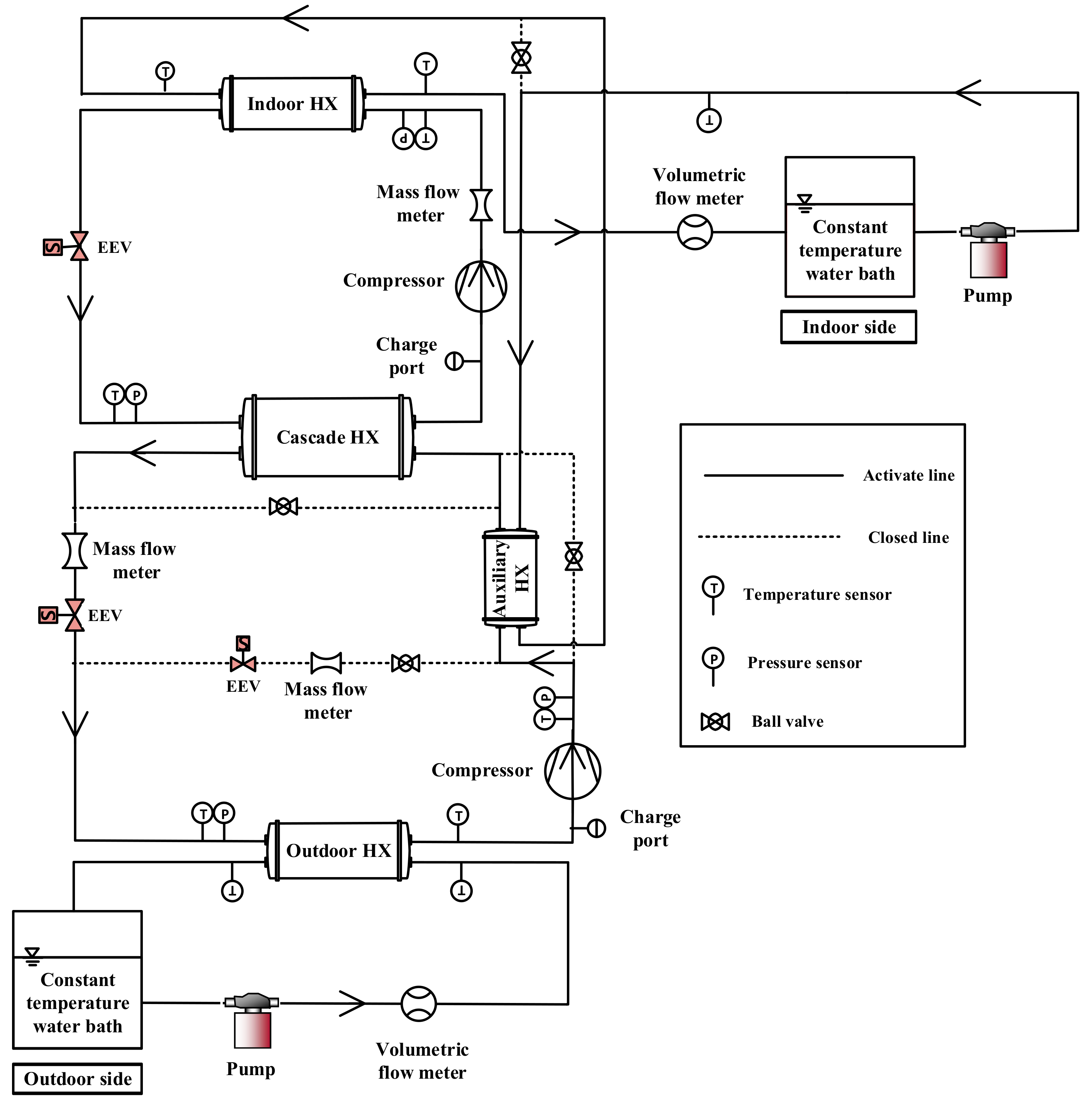
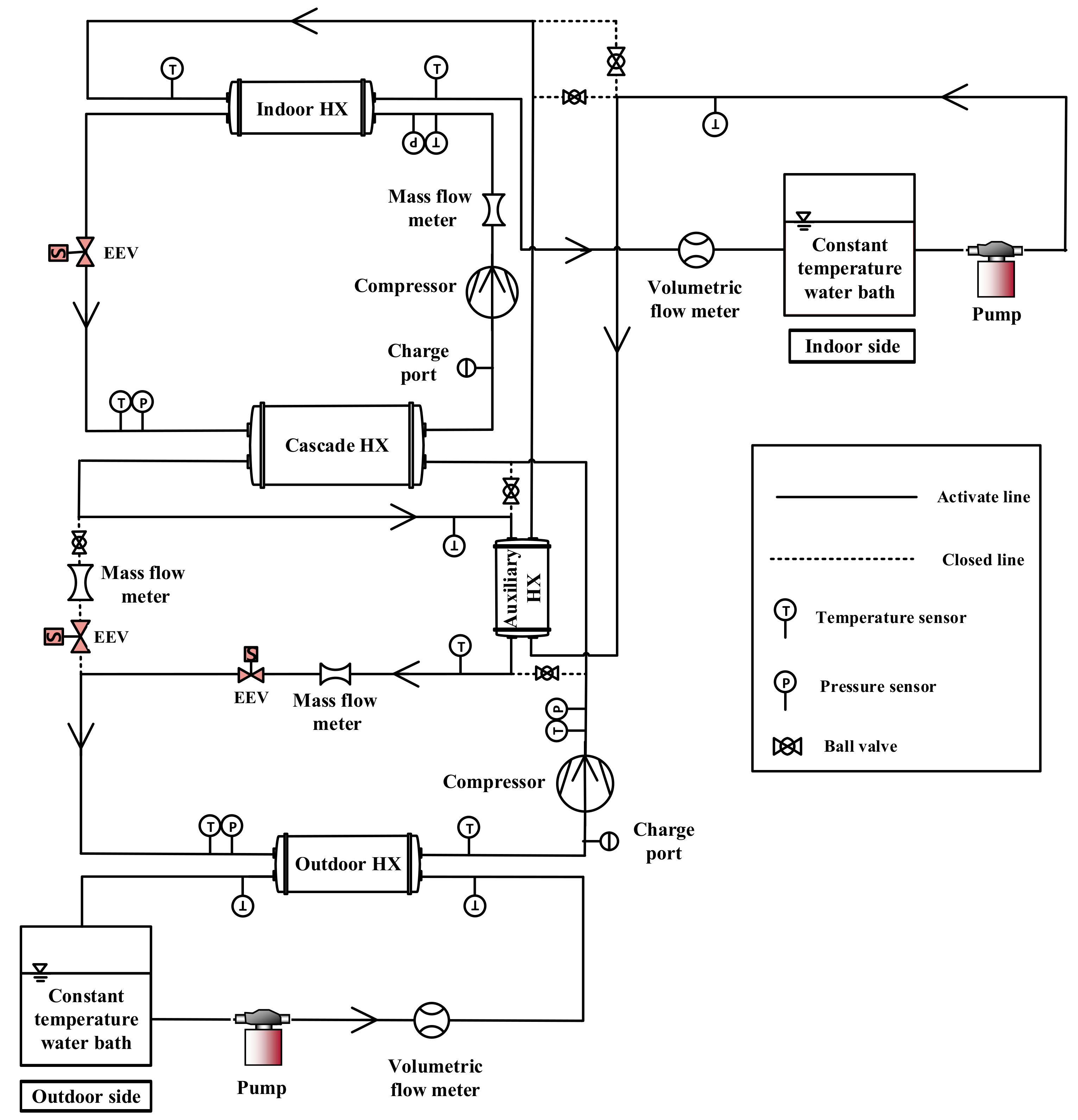
EWT. When AHX was adopted in the LS, heat transfer to secondary fluid of the HS cycle occurred in two stages. Firstly, there was heat transfer to secondary fluid of the HS cycle in the AHX, followed by heat transfer to HS secondary fluid from the AHX in the ID HX. Heat transfer to the HS secondary fluid in the AHX was such that, compressed superheated LS refrigerant exchanged heat with HS secondary fluid in the AHX, resulting in significant heat transfer to the HS secondary fluid when AHX was in desuperheater position. In heater position, subcooled LS refrigerant exchanged heat with HS secondary fluid in the AHX, resulting in heat transfer to the LS refrigerant because AHX EWT was much higher than temperature of LS refrigerant entering the AHX. With AHX in parallel position, high temperature refrigerant from the LS compressor divided into two flow paths. The first part went into the AHX for heat exchange with the HS secondary fluid, while the other part went into the cascade heat exchanger for heat exchange with the HS refrigerant. Low stage refrigerant mass flow rate in the AHX was therefore lower than that of the cycle with AHX in desuperheater and heater positions, as shown in Figure 6. This resulted in lower heat transfer to secondary fluid of the HS cycle in the AHX compared to that of the cascade heat pump cycle with AHX in desuperheater position, even though LS refrigerant temperature entering the AHX was almost similar in both cycles. Consequently, AHX leaving water temperature (LWT) was highest in the cycle with AHX in the desuperheater position, followed by that of the AHX in parallel position in all OD EWT conditions, as shown in Figure 7. At 0 ° C OD EWT, AHX LWT was 56.2 ° C , 55.7 ° C and 53.9 ° C for the cascade heat pump cycles with AHX in desuperheater, parallel and heater positions respectively.
From the AHX, secondary fluid of the HS cycle proceeded to the ID HX for heat exchange with the HS refrigerant. Thus, LWT of the AHX became the ID EWT. Due to heat transfer between LS refrigerant and HS secondary fluid in the AHX, LS condensing temperature of the cascade heat pump cycles with AHX in desuperheater and parallel positions were lower than that of the cycle with AHX in heater position shown in Figure 8.
Evaporating temperature of the HS cycle was also highest in the cycle with AHX as heater due to its highest LS condensing temperature trend, while HS evaporating temperature of the cycle with AHX in desuperheater position was higher than that of the cycle with AHX in parallel position as shown in Figure 9. This was due to higher heat transfer from the LS to HS in the cascade cycle with AHX in desuperheater position, as compared to that of the cascade cycle with AHX in parallel position, as a result of higher LS refrigerant mass flow rate in the cascade cycle with AHX in the desuperheater position. In the HS cycle, condensing temperature was almost similar in the cascade cycles with AHX in desuperheater and heater positions, while that of the cycle with AHX in parallel position was slightly lower, as shown in Figure 10. Furthermore, HS refrigerant mass flow rate was highest in the cycle with AHX as heater followed by that with AHX in desuperheater position as shown in Figure 11. This was due to the trend of their HS pressure difference as shown in Figure 12. Therefore, heat transfer to secondary fluid in the ID HX was highest in the cascade cycle with AHX as heater followed by that with AHX in desuperheater position. However, because ID EWT was highest in the cascade cycle with AHX in desuperheater position, LWT of the ID HX was slightly higher in the cascade heat pump with AHX as desuperheater compared to the cascade cycles in heater and parallel positions as shown in Figure 13. This resulted in higher heating capacity in the cycle with AHX as desuperheater compared to the cascade heat pump cycles with AHX in heater and parallel positions. Thus, heat transfer to HS secondary fluid in the AHX had greater effect on the heating capacity than that in the ID HX. Heating capacity of the cascade cycle with AHX in desuperheater position was higher than that of the cascade cycle with AHX in heater position by 25.1% and 26.0% at OD EWT of −5 ° C and 0   ° C respectively. Additionally, heating capacity of the cascade cycle with AHX in desuperheater position was higher than that of the cascade cycle with AHX in parallel position by 40.9% and 38.0% at OD EWT of −5 ° C and 0 ° C respectively.
Figure 14 shows COP of the cascade heat pump cycles adopting AHX. COP was highest in the cascade cycle with AHX in desuperheater position followed by that with AHX in heater position. The cascade cycle with AHX in parallel position had the lowest COP at all OD EWT conditions. In the cascade cycles with AHX in desuperheater and parallel positions, heat transfer occurred between compressed high temperature LS refrigerant and HS secondary fluid in the AHX. However, heat transfer to secondary fluid in the AHX was higher in the cascade cycle with AHX in desuperheater position because LS refrigerant mass flow rate in the AHX was higher in system with AHX in desuperheater position than that of the cascade cycle with AHX in parallel position. Thus, the LS EEV opening was decreased in the system with AHX in parallel position in order to maintain the same superheat at the LS cycle in both systems. This caused lower LS pressure difference in the cascade cycle with AHX in desuperheater position, as compared to that of the cascade cycle with AHX in parallel position as shown in Figure 15. Moreover, LS pressure difference of the cascade cycle with AHX in heater position was highest due to heat gain by LS refrigerant in the AHX. This resulted in the cascade cycle with AHX in heater position having the highest LS power consumption, followed by that of the cycle with AHX in parallel position. Power consumption of the LS cycle was lowest in the cascade cycle with AHX in desuperheater position.
In the HS cycle, power consumption of the cascade cycle with AHX in heater position was lower than that of the cascade cycle with AHX in desuperheater and parallel positions. This is because HS evaporating pressure was higher in the cascade cycle with AHX in heater position, resulting in lower pressure difference in the HS cycle. Additionally, HS power consumption of the cycle with AHX in desuperheater position was slightly lower than that of the cycle with AHX in parallel position because pressure difference of the HS cycle was lower in the cycle with AHX in desuperheater position. Consequently, total power consumption of the cascade cycle with AHX as heater was highest, due to its high LS power consumption, followed by that of the cascade cycle with AHX in parallel position as shown in Figure 16. Total power consumption of the cascade cycle with AHX as desuperheater was lowest because of its low LS power consumption. Thus, power consumption of the LS cycle had dominant effect on total power consumption of the cascade cycles with AHX.
The high heating capacity of the cascade cycle with AHX in desuperheater position, coupled with its low total power consumption resulted in it having the highest COP among the three cascade heat pump cycles with AHX. At 0 ° C OD EWT, COP of the cascade cycle with AHX in desuperheater was higher than that of the cascade cycles with AHX in heater and parallel positions by 39.0% and 42.5% respectively. Also, at −5 ° C OD EWT, COP of the cascade cycle with AHX in desuperheater position was higher than that of the cascade cycles with AHX in heater and parallel positions by 39.2% and 44.3% respectively. Therefore, OD EWT had no significant effect on the difference in COP between the cascade heat pump cycles with AHX.

3.2. Performance Comparison between Conventional Cascade Heat Pump Cycle and New Cascade Heat Pump Cycle with AHX in Desuperheater Position

Figure 17 shows capacity of the conventional cascade heat pump and that of the cascade heat pump adopting AHX in desuperheater position. The capacity of the cascade heat pump adopting AHX in desuperheater position was higher than that of the conventional cascade heat pump at all OD EWT conditions. Capacity of cascade heat pumps for hot water generation greatly depends on heat transferred to secondary fluid of the HS cycle. In the cascade heat pump with AHX in desuperheater position, heat transfer to HS secondary fluid occurred in the AHX, between LS refrigerant and HS secondary fluid, and in the ID HX, between HS refrigerant and HS secondary fluid. However, in the conventional cycle, heat transfer to secondary fluid of the HS cycle occurred only in the ID HX. The indoor EWT of cascade heat pump with AHX in desuperheater position was higher than that of the conventional cascade heat pump as shown in Figure 18, due to heat transfer from the LS refrigerant to HS secondary fluid in the AHX. Heat transfer in the ID HX of the cycle with AHX in desuperheater position, therefore occurred between HS refrigerant and HS secondary fluid with EWT higher than that of the conventional cycle. For the conventional cycle, LS condensing temperature was higher than that of the cycle with AHX in desuperheater position, as shown in Figure 19. This resulted in higher heat transfer to the HS cycle in the cascade heat exchanger, and higher HS evaporating temperature compared to the cycle with AHX as desuperheater as shown in Figure 20. High stage refrigerant mass flow rate in the conventional cycle was therefore higher than that of the cycle with AHX in desuperheater position as shown in Figure 21, which consequently resulted in higher heat transfer between HS refrigerant and secondary fluid in the ID HX. Even though heat transfer to HS secondary fluid in the ID HX was lower for the cycle with AHX as desuperheater, total heat transfer to the HS secondary fluid was higher than that in the conventional cascade heat pump at all OD EWT conditions. Therefore, LWT of the ID HX was higher in the cycle with AHX as desuperheater as shown in Figure 22, resulting in higher heating capacity for the cycle with AHX in desuperheater position at all OD EWT conditions.
Furthermore, difference in heating capacity between the cycle with AHX as desuperheater and that of the conventional cycle increased as OD EWT increased, due to the increase in heat transfer to secondary fluid of the HS cycle in the AHX. Heating capacity of the cycle with AHX as desuperheater was higher than that of the conventional cycle by 3.7%, 6.1%, 6.6% and 7.4% at OD EWT of −5 ° C , 0 ° C , 5 ° C and 10 ° C respectively.
Figure 23 shows COP of the conventional cascade heat pump and that of the cycle with AHX as desuperheater according to OD EWT variation. COP of the cascade heat pump cycles increased according to increase in OD EWT due mainly to increase in heating capacity. Even though total power consumption of the cascade heat pump cycles increased as OD EWT increased, as shown in Figure 24, the slope of increase of the heating capacity was higher than that of the total power consumption, resulting in the increasing COP trend as OD EWT increased.
Furthermore, COP of the cascade heat pump with AHX as desuperheater was higher than that of the conventional cycle at all OD EWT conditions. Low stage power consumption of the cascade heat pump with AHX as desuperheater was significantly lower than that of the conventional cycle at all OD EWT conditions as shown in Figure 25. This was due to lower LS pressure difference of the cycle with AHX in desuperheater position as shown in Figure 26, caused by lower LS condensing pressure as a result of heat transfer to the HS secondary fluid in the AHX. Nonetheless, HS power consumption of the cascade cycle with AHX in desuperheater position was slightly higher than that of the conventional cycle at all OD EWT conditions. Therefore, total power consumption of the conventional cycle was higher than that of the cycle with AHX as desuperheater. Combined effect of higher heating capacity and lower total power consumption in the cycle with AHX as desuperheater resulted in it having higher COP as compared to that of the conventional cascade heat pump at all OD EWT conditions. COP of the cascade heat pump with AHX as desuperheater was higher than that of the conventional cascade heat pump by 12.2%, 14.9%, 13.2% and 12.4% at OD EWT of −5 ° C , 0 ° C , 5 ° C and 10 ° C respectively.
Figure 27 shows P-h (Pressure-enthalpy) diagram of the conventional cascade heat pump cycle and the new cascade cycle with AHX as desuperheater at standard EWT conditions. Compared to the conventional cycle, the new cascade cycle had lower LS condensing pressure and lower enthalpy difference across the LS compressor. This resulted in lower LS power consumption of the new cascade cycle. Furthermore, enthalpy difference across the ID HX of the new cycle was slightly higher than that of the conventional cycle, representing slightly higher heat transfer in the ID HX of the new cascade cycle; while enthalpy difference across HS compressor of the new cascade cycle was higher than that of the conventional cycle, showing higher HS power consumption of the new cascade cycle. However, enthalpy difference across the LS and HS compressors shows lower total power consumption of the new cascade cycle than that of the conventional cycle.

4. Conclusions

This study analyzed the performance characteristics of cascade heat pump for hot water generation according to variation in outdoor entering water temperature (OD EWT). Capacity and COP of the cascade heat pump increased with increase in OD EWT due to the increase in heat transfer to the HS cycle as a result of increase in intermediate temperature in the cascade heat exchanger.
A new cycle was proposed to enhance performance of the cascade heat pump for hot water generation by adopting auxiliary heat exchanger (AHX) to the LS side of the cascade heat pump in desuperheater, heater and parallel positions. Cascade cycle with AHX in desuperheater position had highest performance because it had the highest heat transfer to secondary fluid of the HS cycle in the AHX, and lowest pressure difference of the LS cycle. Therefore, performance of the new cascade cycle with AHX in desuperheater position was compared with that of the conventional cycle.
Compared to the conventional cycle, the new cascade cycle with AHX in desuperheater position had higher heating capacity and COP due to great heat transfer from the LS cycle to secondary fluid of the HS cycle in the AHX, and significant decrease in power consumption of the LS cycle. The new cascade cycle with AHX in desuperheater position enhanced heating capacity and COP in the ranges of 3.7–7.4% and 12.2–14.9% respectively, when OD EWT increased from −5 ° C to 10 ° C .

Author Contributions

S.B. analyzed experimental data and wrote original draft preparation. J.M.C. conceptualized a research, reviewed the whole manuscript.

Funding

This research was funded by the research fund of Hanbat National University in 2018 (No. 201801270001).

Acknowledgments

This work was supported by Hanbat National University in Korea.

Conflicts of Interest

The authors declare no conflict of interest.

Nomenclature

AHXAuxiliary heat exchanger
COPCoefficient of performance
C p Specific heat (kJ/kg · C)
DSHDesuperheater
EEVElectronic expansion valve
EWTEntering water temperature ( ° C )
HSHigh stage
HXHeat exchanger
IDIndoor
LSLow stage
LWTLeaving water temperature ( ° C )
V ˙ Volumetric flow rate ( m 3 / s )
ODOutdoor
QHeating capacity (kW)
RTDResistance temperature detector
SFFRSecondary fluid flow rate (LPM)
TTemperature( ° C )
U Uncertainty
WPower consumption (kW)
x Nominal value of variable
Subscript
compCompressor
condCondenser
evap
pump
Evaporator
Pump
Greek
ρ Density ( kg / m 3 )

References

  1. Chua, K.J.; Chou, S.; Yang, W.M. Advances in heat pump systems: A review. Appl. Energy 2010, 87, 3611–3624. [Google Scholar] [CrossRef]
  2. Heo, J.; Jeong, M.W.; Baek, C.; Kim, Y. Comparison of the heating performance of air-source heat pumps using various types of refrigerant injection. Int. J. Refrig. 2010, 34, 444–453. [Google Scholar] [CrossRef]
  3. Aikins, K.A.; Lee, S.; Choi, J.M. Technology review of two-stage vapor compression heat pump system. Int. J. Air. Cond. Refrig. 2013, 21, 1330002. [Google Scholar] [CrossRef]
  4. Jung, H.W.; Kang, H.; Yoon, W.J.; Kim, Y. Performance comparison between a single-stage and a cascade multi-functional heat pump for both air heating and hot water supply. Int. J. Refrig. 2013, 36, 1431–1441. [Google Scholar] [CrossRef]
  5. Kim, D.H.; Kim, M.S. The effect of water temperature lift on the performance of cascade heat pump system. Appl. Therm. Eng. 2014, 64, 273–282. [Google Scholar] [CrossRef]
  6. Fiora, J.J.; Lima, C.U.; Junior, V.S. Theoritic-experimental evaluation of a cascade refrigeration system for low temperature applications using the pair R22/R404A. Therm. Eng. 2012, 11, 7–14. [Google Scholar]
  7. Sachdeva, G.; Jain, V.; Kachhwaha, S.S. Performance study of cascade refrigeration system using alternative refrigerants. Int. Sch. Sci. Res. Innov. 2014, 8, 522–528. [Google Scholar]
  8. Park, H.; Kim, D.H.; Kim, M.S. Thermodynamic analysis of optimal intermediate temperatures in R134a-R410A cascade refrigeration systems and its experimental verification. Appl. Therm. Eng. 2013, 54, 319–327. [Google Scholar] [CrossRef]
  9. Sarker, J.; Bhattacharyya, S.; Lal, A. Selection of suitable natural refrigerant pairs for cascade refrigeration system. Inst. Mech. Eng. Part A J. Power Energy 2013, 227, 612–622. [Google Scholar] [CrossRef]
  10. Jadhav, J.S.; Apte, A.D. Review of cascade refrigeration system with different refrigerant pairs. Int. J. Innov. Eng. Res. Technol. 2015, 2, 74–81. [Google Scholar]
  11. Wu, J.; Yang, Z.; Wu, Q.; Zhu, Y. Transient behavior and dynamic performance of cascade heat pump water heater with thermal storage system. Appl. Energy 2012, 91, 187–196. [Google Scholar] [CrossRef]
  12. Park, H.; Kim, D.H.; Kim, M.S. Performance investigation of a cascade heat pump water heating system with a quasi-steady state analysis. Energy 2013, 63, 283–294. [Google Scholar] [CrossRef]
  13. Kim, D.H.; Park, H.S.; Kim, M.S. Optimal temperature between high and low stage cycles for R134a/R410A cascade heat pump based water heater system. Exp. Therm. Fluid Sci. 2013, 47, 172–179. [Google Scholar] [CrossRef]
  14. Nenkaew, P.; Tangthien, C. A study of Transient Performance of A Cascade Heat Pump System. In Proceedings of International Conference on Alternative Energy in Developing Countries and Emerging Economies. Energy Procedia 2015, 79, 131–136. [Google Scholar] [CrossRef]
  15. Soltani, R.; Dincer, I.; Rosen, M.A. Comparative performance evaluation of cascaded air-source hydronic heat pumps. Energy Convers. Manag. 2015, 89, 577–587. [Google Scholar] [CrossRef]
  16. Tarrad, A.H. Perspective Performance Evaluation Technique for a Cascade Heat Pump Plant Functions at Low Temperature Heat Source. International Journal of Economy. Energy Environ. 2017, 2, 13–24. [Google Scholar]
  17. Qu, M.; Fan, Y.; Chen, J.; Li, T.; Li, Z.; Li, H. Experimental study of a control strategy for a cascade air source heat pump water heater. Appl. Therm. Eng. 2017, 110, 835–843. [Google Scholar] [CrossRef]
  18. Ma, X.; Zhang, Y.; Li, X.; Zou, H.; Deng, N.; Nie, J.; Yu, X.; Dong, S.; Li, W. Experimental study for a high efficiency cascade heat pump water heater system using a new near-zeotropic refrigerant mixture. Appl. Therm. Eng. 2018, 138, 783–794. [Google Scholar] [CrossRef]
  19. Boahen, S.; Choi, J.M. Research trend of cascade heat pumps. Sci. China Technol. Sci. 2017, 60, 1597–1615. [Google Scholar] [CrossRef]
  20. International Standard. Water-Source Heat Pumps-Testing and Rating for Performance Part 2 Water-to-Water and Brine-to-Water Heat Pumps; ISO 13256-2; International Standard: Geneva, Switzerland, 1998. [Google Scholar]
  21. ASHRAE. ASHRAE Guideline 2. Engineering Analysis of Experimental Data; ASHRAE: Atlanta, GA, USA, 1986. [Google Scholar]
Figure 1. Schematic diagram of the conventional cascade heat pump.
Energies 12 04313 g001
Figure 2. Schematic diagram of the cascade heat pump with auxiliary heat exchanger (AHX) as desuperheater.
Energies 12 04313 g002
Figure 3. Schematic diagram of the cascade heat pump with AHX as heater.
Energies 12 04313 g003
Figure 4. Schematic diagram of the cascade heat pump with AHX in parallel with cascade heat exchanger.
Energies 12 04313 g004
Figure 5. Heating capacity of cascade heat pump cycles with AHX according to variation in outdoor entering water temperature (OD EWT).
Energies 12 04313 g005
Figure 6. Low stage refrigerant mass flow rate in AHX according to variation in OD EWT.
Energies 12 04313 g006
Figure 7. AHX leaving water temperature of cascade heat pump cycles with AHX according to variation in OD EWT.
Energies 12 04313 g007
Figure 8. Low stage (LS) condensing temperature of cascade heat pump cycles with AHX according to variation in OD EWT.
Energies 12 04313 g008
Figure 9. High stage (HS) evaporating temperature of cascade heat pump cycles with AHX according to variation in OD EWT.
Energies 12 04313 g009
Figure 10. HS condensing temperature of cascade heat pump cycles with AHX according to variation in OD EWT.
Energies 12 04313 g010
Figure 11. HS refrigerant mass flow rate of cascade heat pump cycles with AHX according to variation in OD EWT.
Energies 12 04313 g011
Figure 12. HS pressure difference of cascade heat pump cycles with AHX according to variation in OD EWT.
Energies 12 04313 g012
Figure 13. Indoor heat exchanger LWT of cascade heat pump cycles with AHX according to variation in OD EWT.
Energies 12 04313 g013
Figure 14. COP of cascade heat pump cycles with AHX according to variation in OD EWT.
Energies 12 04313 g014
Figure 15. Pressure difference of LS cycle of cascade heat pump cycles with AHX according to variation in OD EWT.
Energies 12 04313 g015
Figure 16. Total power consumption of cascade heat pump cycles with AHX according to variation in OD EWT.
Energies 12 04313 g016
Figure 17. Heating capacity of conventional cascade heat pump and cycle with AHX according to variation in OD EWT.
Energies 12 04313 g017
Figure 18. Indoor entering water temperature (ID EWT) of conventional cascade heat pump and cycle with AHX according to variation in OD EWT.
Energies 12 04313 g018
Figure 19. LS saturation temperature of conventional cascade heat pump and cycle with AHX according to variation in OD EWT.
Energies 12 04313 g019
Figure 20. HS saturation temperature of conventional cascade heat pump and cycle with AHX according to variation in OD EWT.
Energies 12 04313 g020
Figure 21. Refrigerant mass flow rate of conventional cascade heat pump and cycle with AHX according to variation in OD EWT.
Energies 12 04313 g021
Figure 22. Leaving water temperature of ID HX of conventional cascade heat pump and cycle with AHX according to variation in OD EWT.
Energies 12 04313 g022
Figure 23. COP of conventional cascade heat pump and cycle with AHX according to variation in OD EWT.
Energies 12 04313 g023
Figure 24. Total power consumption of conventional cascade heat pump and cycle with AHX according to variation in OD EWT.
Energies 12 04313 g024
Figure 25. Power consumption of conventional cascade heat pump and cycle with AHX according to variation in OD EWT.
Energies 12 04313 g025
Figure 26. Pressure difference of conventional cascade heat pump and cycle with AHX according to variation in OD EWT.
Energies 12 04313 g026
Figure 27. P-h (Pressure-enthalpy) diagram of conventional cascade heat pump cycle and new cascade cycle.
Energies 12 04313 g027
Table 1. Component specifications of cascade heat pump unit.
ComponentManufacturerTypeSpecification
LS compressorSiam compressor industryScroll3.5 kW
HS compressorSiam compressor industryScroll3.5 kW
LS expansion deviceParker HannifinEEVStep motor driven
HS expansion deviceParker HannifinEEVStep motor driven
ID HXDOOILDouble tube heat exchanger3.5 kW
OD HXDOOILDouble tube heat exchanger3.5 kW
Cascade HXDOOILDouble tube heat exchanger3.5 kW
Table 2. Test conditions.
ParameterConventional CycleAHX as DesuperheaterAHX in Heater and Parallel Positions
ID WATER BATH LWT ( ° C )555555
OD EWT ( ° C )−5, 0, 5, 10−5, 0, 5, 10−5, 0
OD HX SFFR (LPM)888
ID HX SFFR (LPM)888
LS/HS EEVAdjustedAdjustedAdjusted
Table 3. Sensor accuracies.
SensorAccuracy
Thermocouples±0.2 ° C
Pressure transducer±0.06%
Mass flow meter±0.1%
Power meter±0.1%
Volumetric flow meters±0.5%
RTD sensors±0.15 ° C

