Abstract
With the increasing penetration of renewable energy sources into modern power systems, parallel inverters with LCL filters are commonly employed in the grid interface, giving rise to potential resonance problems. Among the different resonances, interactive resonance is triggered by interaction among inverters when different current references are applied to parallel inverters. It may also feature a mutual current that circulates among inverters instead of flowing into the grid and introduces harmonics or instability in the control system. In this paper, active disturbance rejection control based on a reduced-order extended state observer (RESO) was proposed for parallel inverters. With the proposed scheme, the interaction between inverters is considered as an exogenous disturbance caused by other parallel inverters, estimated by the RESO, and rejected by the controller. In the results, the mutual current and interactive harmonics, calculated via fast Fourier transform, were reduced with the proposed control scheme. Thus, the lower total harmonic distortion of each current was achieved. Additionally, the robust stability and less model-dependent control design are the other additive advantages over the derivative filtered capacitor voltage feedforward-based active damping using PI control. The simulation and real-time experimental results of the conventional and proposed scheme, obtained using the hardware-in-loop, were presented to verify the theoretical analysis under the similar and different current reference cases.
1. Introduction
1.1. Motivation and Incitement
Interest in distributed power-generation systems based on renewable energy sources (RESs) for sustainable development of the environment is growing. In this context, the pulse-width-modulated grid-connected inverter (GCI) has become the most widespread topology for delivering high-quality power from RESs to the grid. To attenuate the high-frequency switching harmonics generated by pulse-width modulation (PWM), the LCL filter has been increasingly adopted between the inverter and power grid [1].
The inherent resonance in the LCL filter can make the controller very complex and require a proper design with consideration of the grid impedance to avoid instability [2,3]. In renewable energy systems, it is common to connect multiple inverters in parallel with the grid to enhance the total generation capacity, leading to the resonance issue becoming more complex [4]. In such systems, internal, series, and interactive resonances have been observed [5]. Among them, interactive resonance, which is also known as parallel resonance, arises, owing to the mutual interaction between parallel GCIs operating under different current references [5,6,7].
1.2. Literature Review
Several studies have been conducted to mitigate the interactive resonance by introducing a virtual harmonic resistance [5], an active damper based on a high-bandwidth power converter [8], or capacitor current-based active damping [9,10,11]. The interactive resonance causes a mutual current—also known as an interactive current—which circulates among inverters instead of flowing into the grid. The relationship between the mutual current and the interactive resonance has been derived, and the adverse effects of the mutual current on the stability of parallel GCIs have been investigated [6,7,12]. However, in these studies, the harmonics introduced by the mutual current were not considered. In [13], the mutual current harmonics were investigated. The harmonics were divided into the low- and high-frequency components. However, the current-reference uncertainty in the RESs was not considered. In previous studies [14,15,16], the instability caused by the mutual current has been investigated under asynchronous PWM carriers or grid-impedance variation. However, the mutual current harmonics may increase the total harmonic distortion (THD) of inverter currents under operation with different references. The general LCL filter design guideline for preventing mutual current instability is provided in [17]. However, the dynamics of currents under different current references were not considered. Thus far, no effective solution for reducing the mutual current and harmonics under different current references in multi-parallel GCIs has been reported.
Active disturbance rejection control (ADRC), which is a disturbance observer-based control method, provides an active and effective way to handle complex/uncertain systems with minimal information about the system [18]. The ADRC estimates all the exogenous and endogenous disturbances, as a value called the lumped disturbance, in the system with the model-independent extended state observer (ESO), which is the main part of ADRC, and compensates them in the control law [19]. The reduction of the resonance harmonics for the LCL filter type GCI was investigated with ADRC in [20,21,22].
1.3. Contribution and Paper Organization
In this paper, a mutual current and resonance harmonics reduction scheme for multi-parallel GCIs with the reduced-order ESO (RESO)-based ADRC, irrespective of the current reference, was proposed. In addition, the common and mutual current expressions were derived with the proposed scheme. The interactive resonance among inverters was treated as an exogenous disturbance, estimated by RESO, and compensated by the proposed scheme. The damping of interactive and common resonances with the proposed method is explained by the frequency response method in the z-domain under different numbers of parallel inverters. The effective resonance damping resulted in greatly reduced mutual current and harmonics in the parallel grid-connected inverters. Furthermore, the stability of the system and disturbance rejection capabilities of the system were analyzed and compared with the conventional PI control using the derivative filter capacitor voltage feedforward-based active damping. To verify the performance of the proposed scheme, several experiments and harmonic analyses were performed for a system composed of two 3kVA inverters in parallel, to consider the worst case, using the real-time hardware-in-loop (HIL) simulation under similar and different reference cases.
The rest of the paper is organized as follows. The mathematical model of the multi-parallel GCI system with LCL filters is derived in Section 2. In Section 3, each element of the overall system with the proposed control scheme is explained, and the design guidelines for the RESO are provided. The common and mutual current expressions in relation to the current reference with the proposed method are derived in Section 4. In Section 5, the resonance damping, stability analysis, and disturbance rejection capabilities of the proposed scheme are presented and compared with those of the conventional derivative filtered capacitor voltage feedforward-based active damping. A simulation and real-time experimental verification for validating the analysis performed in the preceding sections under different current-reference conditions are presented in Section 6. Conclusions are drawn in Section 7.
2. Mathematical Modeling of Multi-Parallel GCIs
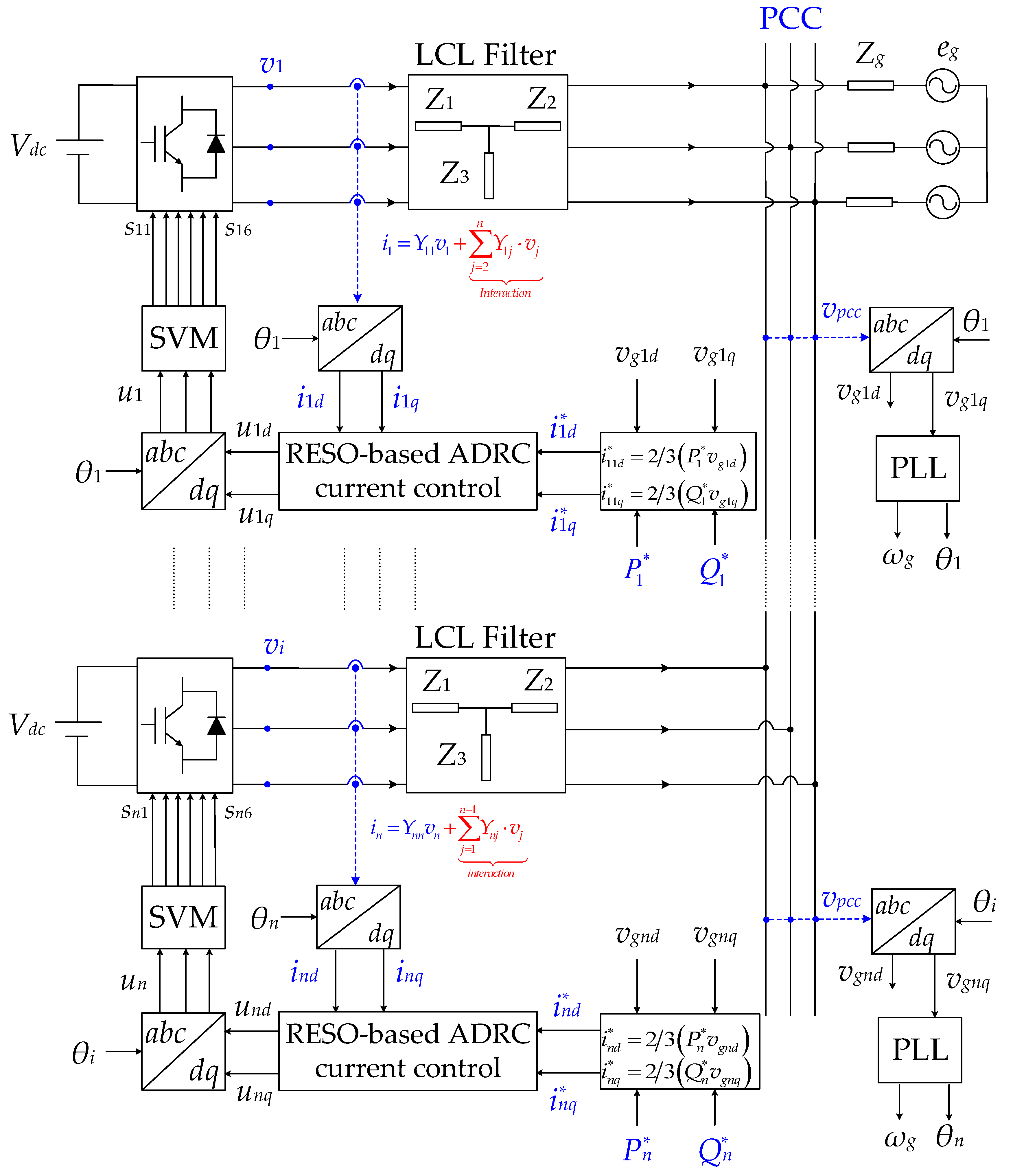
The operation of multiple (n) parallel three-phase GCIs with LCL filters is shown in Figure 1. Each inverter is provided with a constant DC voltage Vdci (i = 1,…, n). Z1i and Z2i represent the inverter- and grid-side inductor impedances, respectively, Z3i represents the filter capacitance impedances, and Zg represents the inductive grid impedance. The inverter-side currents and voltages are represented by ii and vi, respectively. eg represents the ideal and balanced grid voltage, and vpcc represents the voltage at the point of common coupling (PCC). The inverter parameters are assumed to be identical, i.e.,
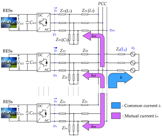
Figure 1.
Renewable energy sources (RESs)-based LCL filter-type multi-parallel three-phase grid-connected inverters (GCIs).
Each current ii makes (n − 1) minor contributions to the other j inverters and one major contribution to the grid. The minor contribution is defined as mutual currents imj (j = 1,…, n and j ≠ i), which circulate among other inverters. The major contribution is defined as a common current ic. The multi-parallel GCIs is a multi-input-multi-output system [23]. The relationship between the output currents ii and input voltages vi for multi-parallel GCIs can be derived as
where Y(s) is the n × n admittance matrix of the system. In Equation (2), the impact of each inverter’s own voltage vi(s) on its own current ii(s) is represented by diagonal elements Yii(s), and the impact of other inverter voltages vj(s) on the current ii(s) is represented by non-diagonal elements Yij(s). For an n parallel inverter system, an index i corresponds to the inverter under consideration, and an index j corresponds to each of the remaining (n − 1) inverter modules. All the diagonal elements are the same when we assume identical parameters for each inverter. Similarly, all non-diagonal elements are the same. By using the superposition principle, the diagonal and non-diagonal elements can be derived as [6,7,12]
where Gplant(s) and Gcoupling(s) represent the LCL filter transfer function and grid impedance coupling transfer function, respectively.
Here, ωres and ωres1 are defined as the interactive and common resonance frequencies, respectively.
From Equation (4), it can be easily seen that Gplant (s) and Gcoupling (s) become identical when Lg is zero, and accordingly, all the non-diagonal elements Yij(s) become zero. Consequently, no interaction among inverters is observed [7]. However, when Lg is not zero, each inverter interacts with not only a grid but also the other inverters. In this case, the current ii(s) can be expressed as
where ims(s) represents the sum of (n − 1) contributions of current ii(s) as a mutual current.
From Equation (2), ii(s) can be expressed as
From Equations (3), (6) and (7), the currents ims(s) and ic(s) are derived as
Note that ims(s) depends on Gplant(s) and becomes zero when all the inverter voltages are the same. After applying a abc to dq transformation to Equation (8), we obtain
where and (s) are the dq components of currents ims(s) and ic(s), respectively. Similarly, and are the dq components of voltages vi(s) and vj(s), respectively. The term ωg(L1+L2) in the mutual current and ωg(L1+L2) in the common current represent the coupling effect between the respective dq variables. The transfer functions and can be derived as
where ωg represents the grid frequency. All the parameters of the multi-parallel GCIs are presented in Table 1.

Table 1.
System parameters of multi-parallel GCIs.
3. Proposed Mutual Current Reduction Scheme
The overall system with the proposed RESO-based ADRC current control scheme for the multi-parallel three-phase GCIs is shown in Figure 2, where and represent the d and q components of ii, respectively, and and represent the d and q components of vpcc, respectively. The current ii, which is influenced by all the other j inverters voltages vj, is chosen as a feedback to the current control. The vpcc is sensed only for the current and voltage synchronization around ωg with the phase-locked loop (PLL). The current references and are generated independently by the active power Piref and reactive power Qiref references applied to each inverter, respectively. The six-pulse IGBT gate signals si1 to si6 are also generated separately for each inverter by applying space-vector modulation (SVM) to the control signals provided by each RESO-based ADRC control block after performing inverse dq transformation on control signals and . For and regulations, the inverters have decentralized control blocks with identical structures and no communication.
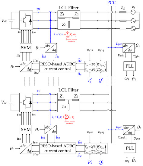
Figure 2.
Overall system with the proposed reduced-order extended state observer (RESO)-based active disturbance rejection control (ADRC) current control scheme.
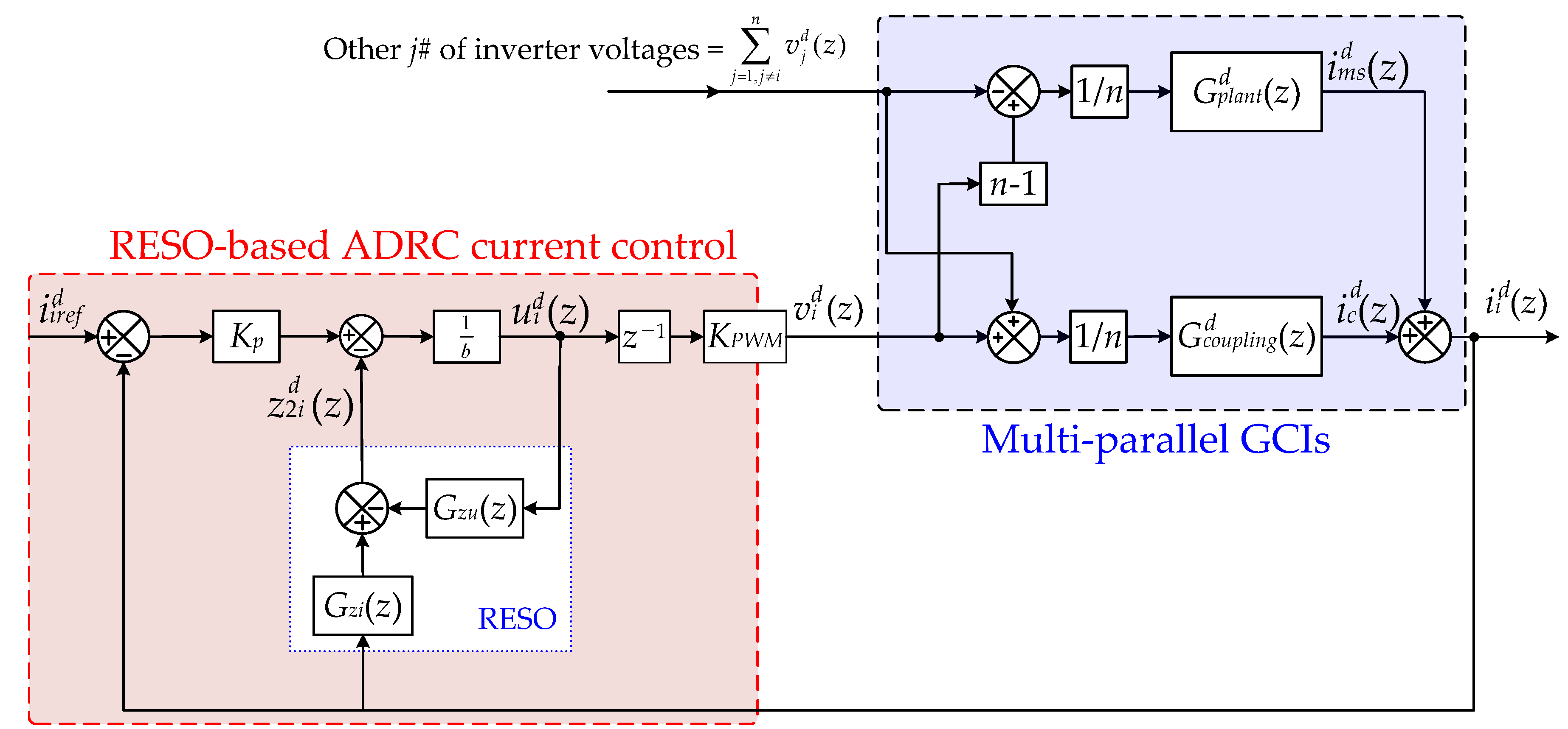
The detailed diagram with the proposed control scheme from Figure 2 for any inverter i in the z-domain is shown in Figure 3. In this paper, only (z) regulation is explained, for simplicity, and a similar configuration for (z) regulation is adopted. The (z) is compared with , followed by proportional control with the gain Kp selected according to the required performance of the control. The estimated lumped disturbance calculated by the RESO is subtracted to compensate for the exogenous disturbance, i.e., the effect of the sum of the other j inverters voltages. In the result, the control signal (z) is generated after dividing by the turning parameter b, which is equal to 1/L1. The z−1 represents an inherent delay caused by computation and the PWM update, and the inverter is simplified as a linear amplifier with gain KPWM. Finally, the (z) is generated. Similarly, (z) is generated by (z) current regulation of any other j inverters. The control plant, which comprises multi-parallel GCIs in the discrete time domain is represented as a block-diagram according to Equation (9). With the consideration of the zero-order-hold (ZOH) effect in Figure 3, the discrete representations of and are given as [24]
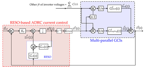
Figure 3.
Overall system with the proposed RESO-based ADRC current control scheme. Proposed RESO-based first-order ADRC current control scheme for multi-parallel GCIs.
With the proposed scheme, the interaction influence of other inverters on each current can be treated as an exogenous disturbance, whereas the coupling effect between the dq variables is treated as an endogenous disturbance.
In general, the state-space model of a first-order time-delayed system with an extended state can be represented as
where x1(t) and x2(t) represent the system states and y(t) is the output of the system. b is the control gain parameter, uc(t − Ts) is the control input with a time delay of sampling time Ts, and f(t) represents the lumped disturbance in the system.
Generally, the second-order ESO, which is the core part of first-order ADRC, is constructed as
where z1(t) and z2(t) are the estimated values of x1(t) and x2(t), respectively, and is the gain matrix of the ESO.
Assuming that x1(t) is known through measurement, Equation (13) can be reduced to an estimation of z2(t):
Using Equation (12), we can rewrite Equation (14) as
where the observer gain β2 is selected as an observer bandwidth ωo.
After applying the Laplace transform to Equation (15) and separating the two terms uc(s) and y(s), the output-to-estimation transfer function Gzy(s) and the control-to-estimation transfer function Gzu(s) are derived as
Transforming Equation (16) into the discrete time domain with consideration of the zero-order-hold (ZOH) effect and then replacing y(z) with (z), uc(z) with (z), and z2(z) with (z) yields the following Gzi(z) and Gzu(z) in Figure 3:
4. Modeling of the Proposed Scheme
In this section, the overall dynamics of the system with the proposed control scheme are modeled. From Figure 3, (z) and (z) can be expressed as
By substituting Equations (17) and (18) into Equation (19), we obtain
where G1(z) and G2(z) are defined as follows:
With a well-tuned RESO, the observer output (z) closely tracks the lumped disturbances in the multi-parallel GCIs. The proposed scheme can actively compensate for the effect of lumped disturbances in real time. As indicated by Equation (21), the proposed scheme does not rely on detailed knowledge of the system. The expression for (z) from Figure 3 based on Equation (20) are derived as follows:
Similarly, the expression for (z) can be derived as
By substituting Equations (22) and (23) into Equation (24), (z) can be expressed as
By substituting Equation (26) into Equation (25), the relationship between (z) and all the current references can be obtained:
By substituting Equations (22) and (23) into Equation (28), (z) can be expressed as
The current (z) arises only when dissimilar currents exist among inverters; therefore, we obtain
By substituting Equation (30) into Equation (29), the following expression for (z) is obtained:
It can be observed from Equation (31) that when = , the mutual current dynamics can be ignored.
By applying the dq transformation and discretizing Equation (6), the expression for the current (z) can be obtained:
Substituting Equations (27) and (31) into Equation (32) gives the complete expression of (z):
The expression in Equation (33) can be simplified by separating the (z)/(z) and (z)/(z) characteristics and introducing T(z) and R(z):
where Gmut(z) and Gcom(z) are the two closed-loop transfer functions representing the (z) and (z), respectively, from Equation (34) and are expressed as
The performance of the multi-parallel GCIs can be evaluated using Equation (34), which includes ims(z) and ic(z) dynamics simultaneously.
5. Resonance Damping and Stability Analysis
The multi-parallel GCIs system is stable if and only if the currents ims(z) and ic(z) are stable. From Equation (35), the loop-gain expressions Tc(z) and Tm(z) for the common and mutual current stability, respectively, are obtained as
and
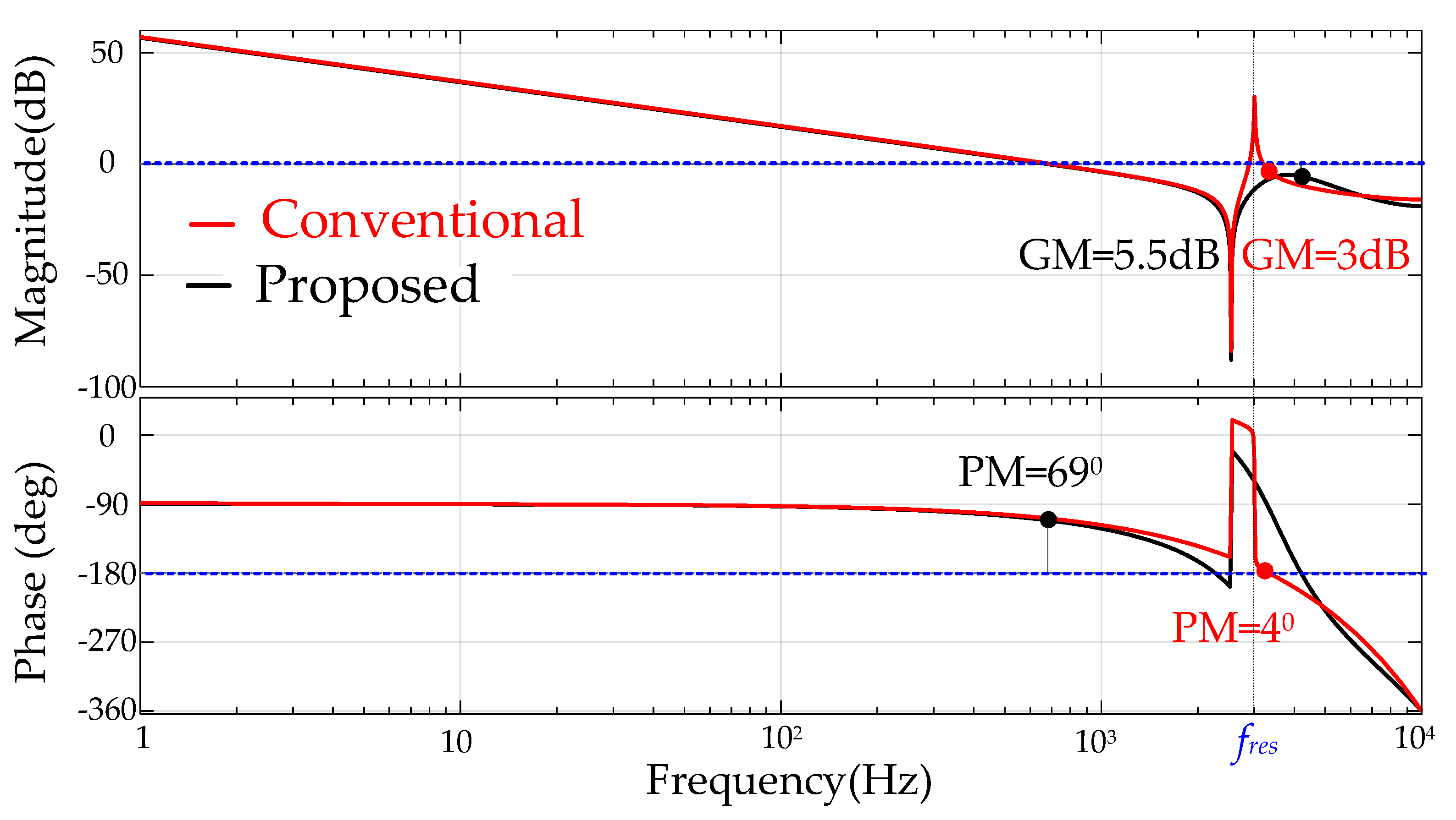
The resonance damping was analyzed via the frequency-response method using Bode plots with different values of n. The stability analysis was performed on the Bode plot by using the Nyquist stability criterion in the frequency range above 0 dB to find the phase margin (PM) of the system above the −180° phase line. Additionally, the gain margin (GM) of the system is measured to determine how much increase in the control bandwidth is possible. The parameters of the proposed control scheme are given in Table 2. The parameter b in the proposed scheme plays an important role in achieving a larger observer bandwidth to improve the disturbance estimation performance of the RESO. A higher value of ωo can be obtained when a higher value of b is adopted. Generally, ωo is limited by the sampling frequency fs [20]. The Bode plot of the loop gain of the mutual current with the proposed scheme is compared with that of conventional derivative filtered capacitor voltage-based active damping using PI control [7] in Figure 4. The corresponding loop-gain expressions for the conventional scheme are provided in the Appendix A (Equations (A1) and (A2)). The figure indicates that the interactive resonance in the mutual current is independent of the number of parallel inverters. Hence, the frequency response of the mutual current remains the same under different values of n. A small PM of 4° is observed with the conventional scheme owing to the ineffective resonance damping. Additionally, the resonance peak at fres amplifies the resonance, which introduces the mutual current in the parallel GCIs. Moreover, a further increase in the bandwidth of the conventional scheme may violate the system stability. However, the proposed scheme effectively damps the interactive resonance and achieves a larger PM of 69° and a similar crossover frequency as the conventional scheme. With the proposed scheme, no resonance peak is observed above 0 dB at fres, which results in a significantly reduced mutual current in the parallel GCIs.
Table 2.
Parameters of RESO-based ADRC current control.

Figure 4.
Frequency response of loop gain of mutual current under n = 2, 4, 8, 16, 32 and 64 with the conventional and proposed control scheme.
The frequency response of the loop gain of the common current with the conventional scheme under different values of n is shown in Figure 5. The ωres1 is a variable frequency depending on the number of parallel inverters at the PCC; hence, the frequency-response characteristics of the common current are varied according to n. As indicated by the figure, the conventional scheme cannot achieve enough resonance damping, and its disturbance rejection capabilities are highly affected with an increase in the number of inverters. Additionally, only a small PM in the range of 11°–23° is achieved with the conventional scheme, which limits the bandwidth of the control. In contrast, the proposed scheme effectively damps the common resonance regardless of n and maintains a higher stability of the system, disturbance-rejection capabilities, and the crossover frequency of the control, as shown in Figure 6.
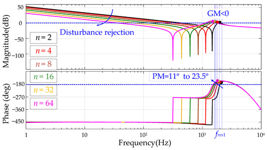
Figure 5.
Frequency response of the common current under n = 2, 4, 8, 16, 32 and 64 with the conventional control scheme.
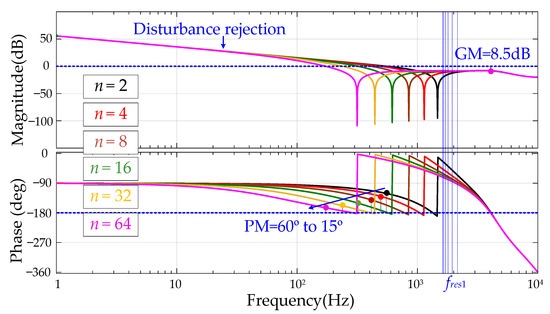
Figure 6.
Frequency response of the common current under n = 2, 4, 8, 16, 32 and 64 with the proposed control scheme.
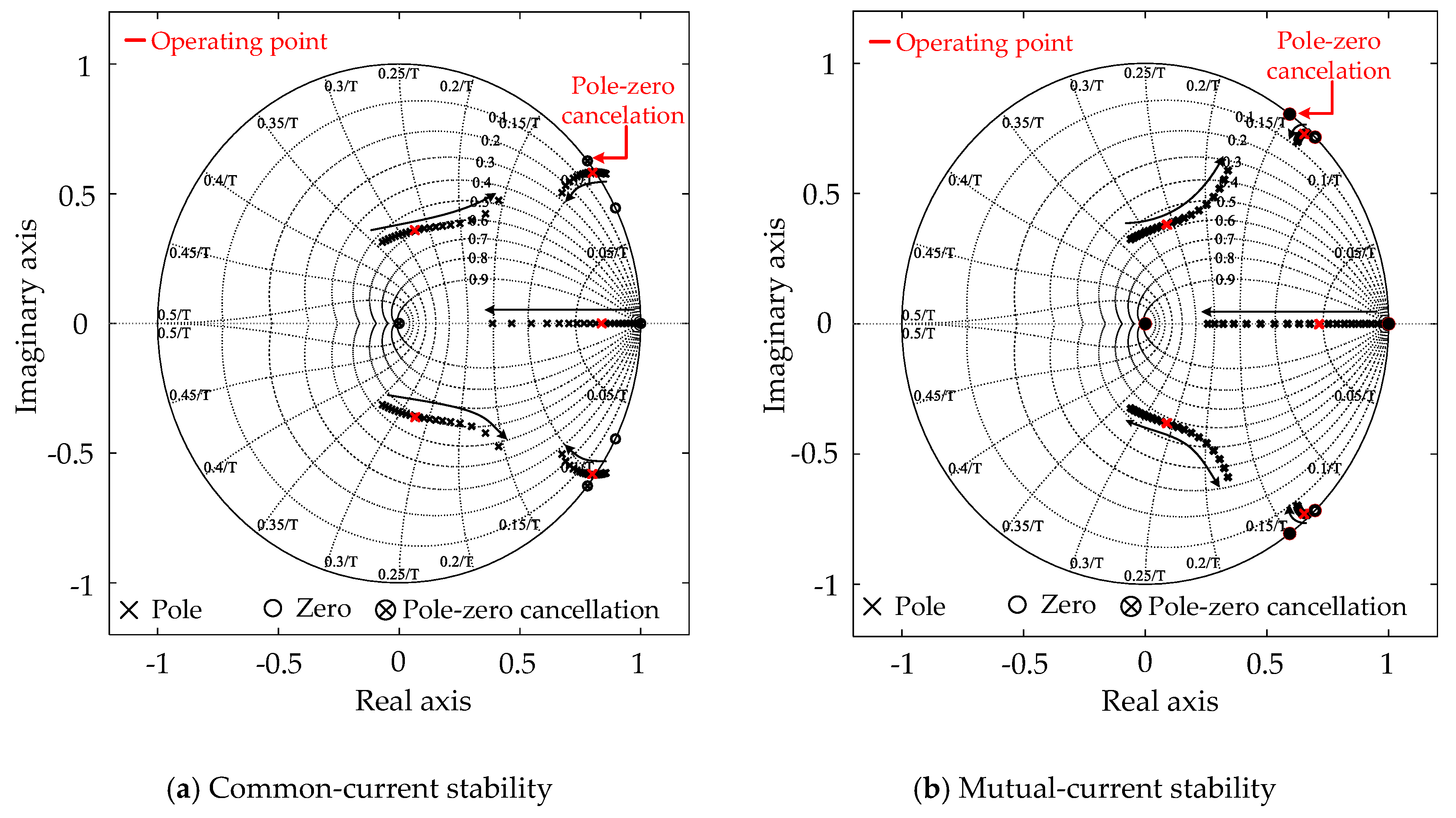
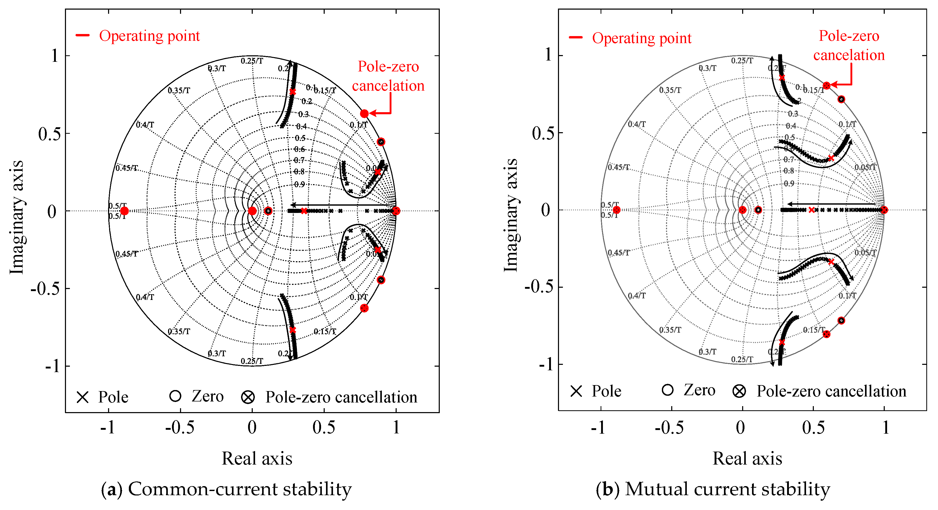
Figure 7a,b show the pole-zero maps of the closed-loop transfer functions Gcom_PI(z) and Gmut_PI(z) with the conventional scheme for two parallel GCIs under kp variation. As shown in Figure 7, the conventional scheme introduces a pole near the unit circle in the common and mutual current, which causes resonance in the system and reduces the stability margin of the system. However, in the pole-zero map of the proposed scheme shown in Figure 8a,b, we observe that the common and interactive resonances are compensated via pole-zero cancelation. Additionally, the common- and mutual-current poles are well inside the unit circle. Hence, the entire system is commonly and mutually stable.

Figure 7.
Pole-zero movement of Gcom_PI(z) and Gmut_PI(z) under kp variation with n = 2.
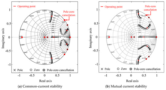
Figure 8.
Pole-zero movement of Gcom(z) and Gmut(z) under Kp variation with n = 2.
6. Performance Verification
The proposed scheme was verified by simulation and real-time experimental implementation via the HIL technique with a 1 µs step size for the two-parallel GCIs, where the control algorithm was implemented using real-time digital control circuitry.
The performance of the proposed scheme was investigated under two cases: Case I represents the different current references, i.e., = 5 A and = 0, and Case II represents the same current references, i.e., = 5 A and = 5 A to each inverter. The current references and to the q-axis current control of inverters #1 and #2 remain zero in both cases.
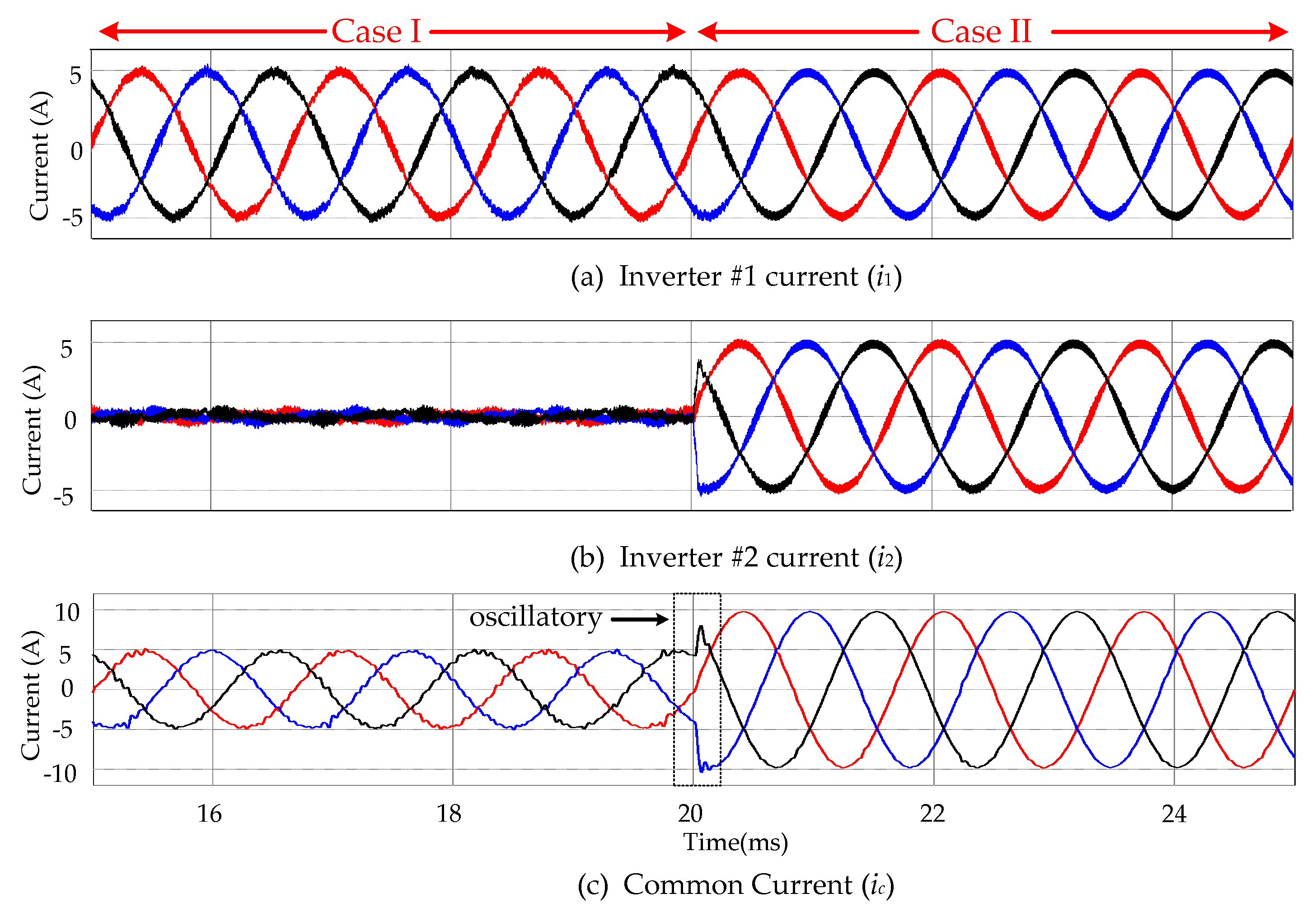
Figure 9 shows the simulation response of the conventional scheme illustrated in [7]. During Case I, the mutual current is generated in the inverter #2 current, as shown in Figure 9b, owing to the ineffective interactive resonance damping. Consequently, more resonance harmonics are observed in i1 and ic of Figure 9a,c compared with Case II. Additionally, some oscillations during a step change at 20 ms are observed in the common current shown in Figure 9c.
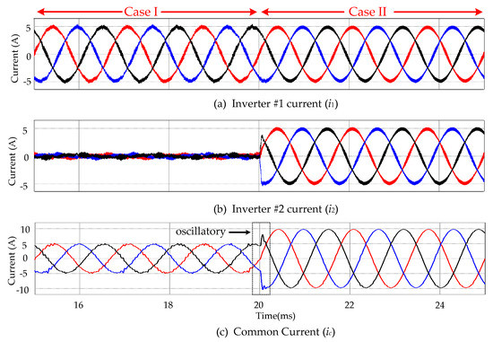
Figure 9.
Simulation results for Cases I and II under the conventional scheme presented in [7].
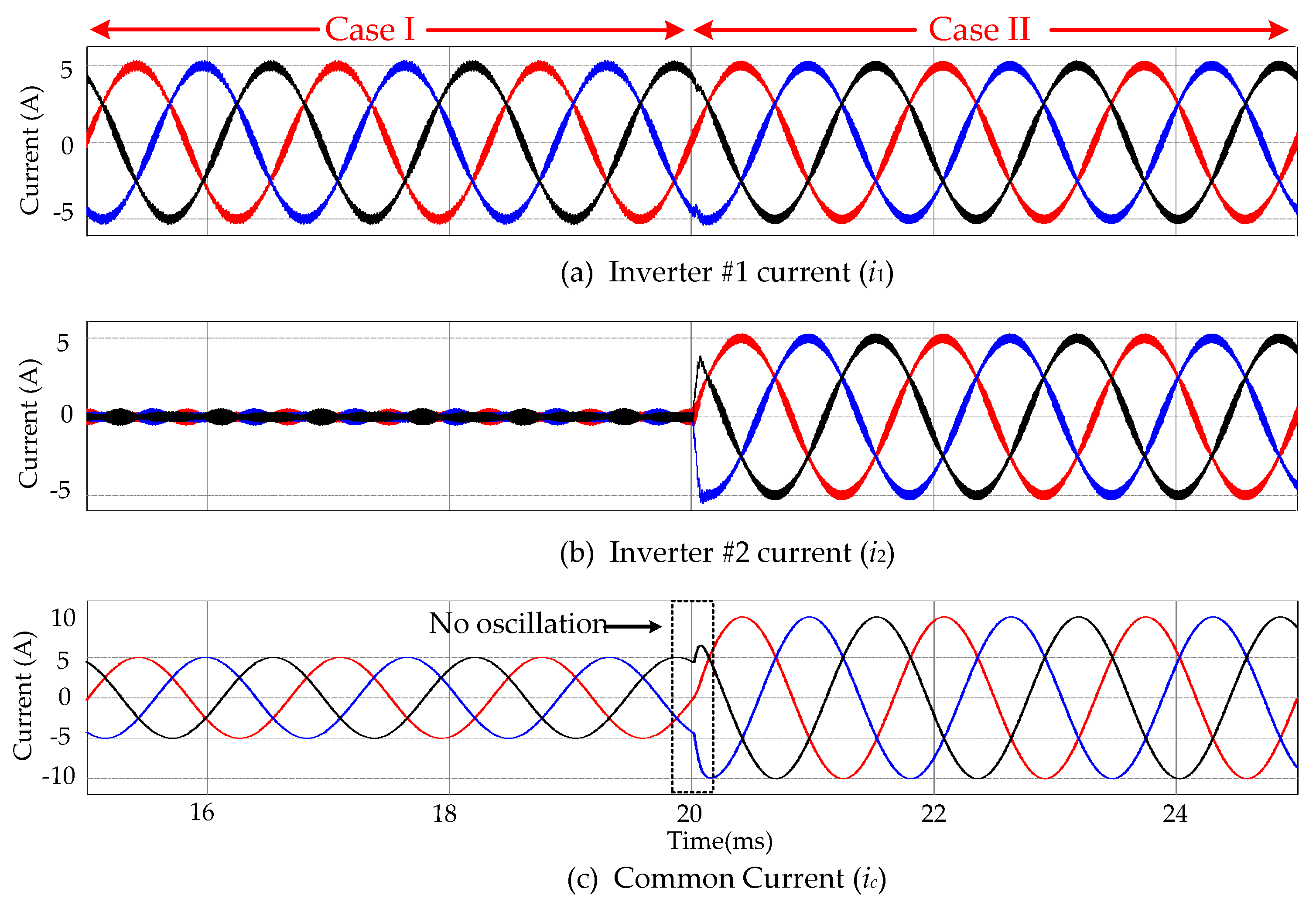
In Figure 10, the simulation responses of the proposed scheme are shown. The proposed scheme effectively damps the common and interactive resonance in Cases I and II. Consequently, no mutual current is observed in the inverter #2 current of Figure 10b. Additionally, no interactive resonance harmonics are observed in i1 and ic of Figure 10a,c for both Cases I and II. The smooth tracking response of the common current shown in Figure 11c during a step change at 20 ms explains the larger stability margin, as described in Section 5.
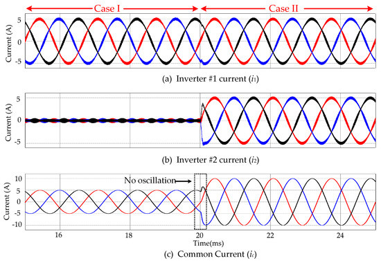
Figure 10.
Simulation results for Cases I and II under the proposed scheme.
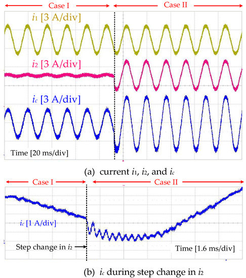
Figure 11.
Experimental results for Cases I and II under the conventional scheme presented in [7].
The real-time experimental results of the conventional scheme for Cases I and II are shown in Figure 11. With the adoption of Case I, the mutual current is activated and circulates in inverter #2, as indicated by i2. The mutual current introduces harmonics in i1, i2 and ic during Case I. During Case II, the mutual current is zero, and interactive resonance harmonics do not exist. Additionally, during the step change in inverter #2 from Case I to II, oscillations in the common current are observed, as shown in Figure 11b, which depicts the simulation performance shown in Figure 10.
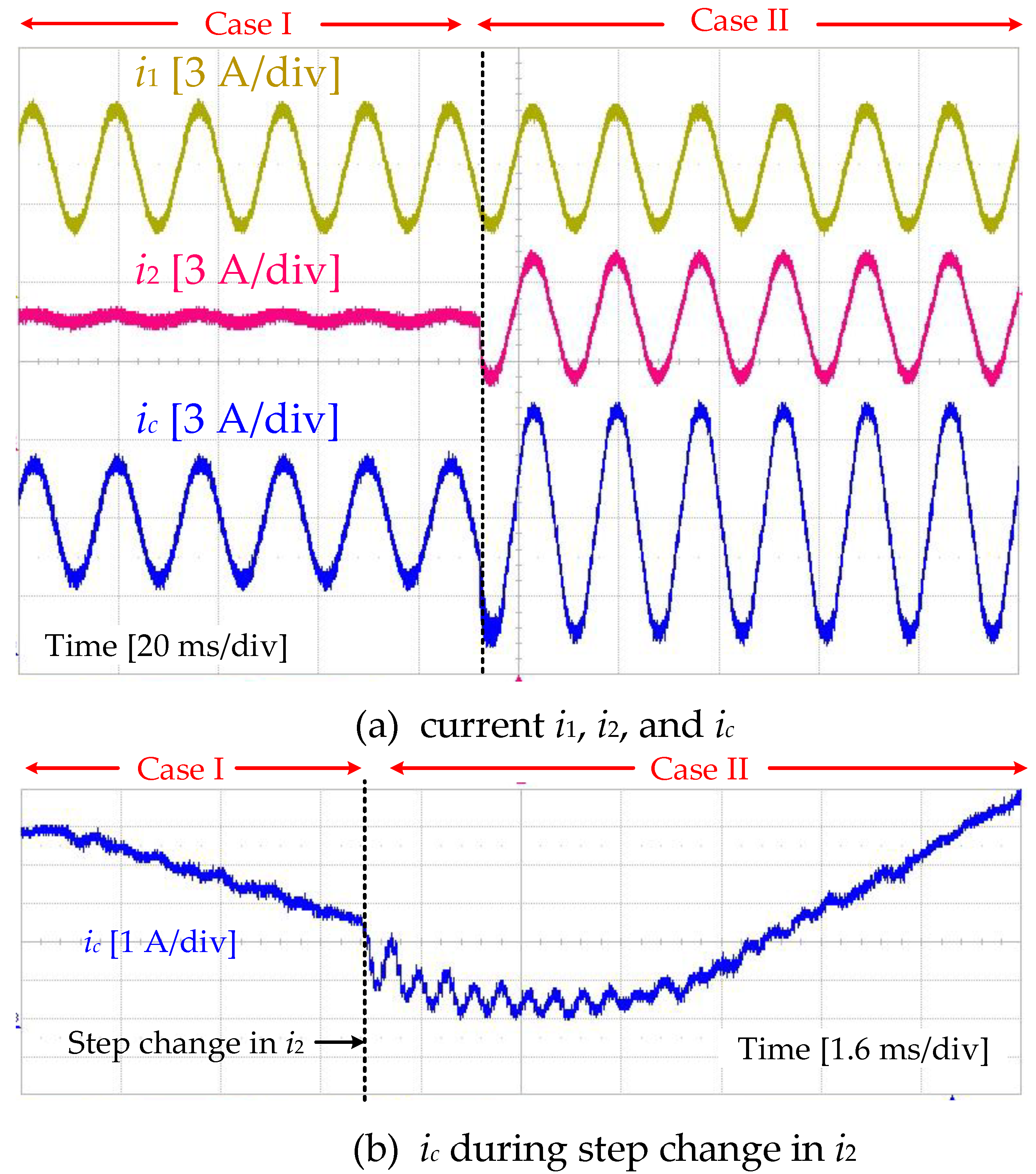
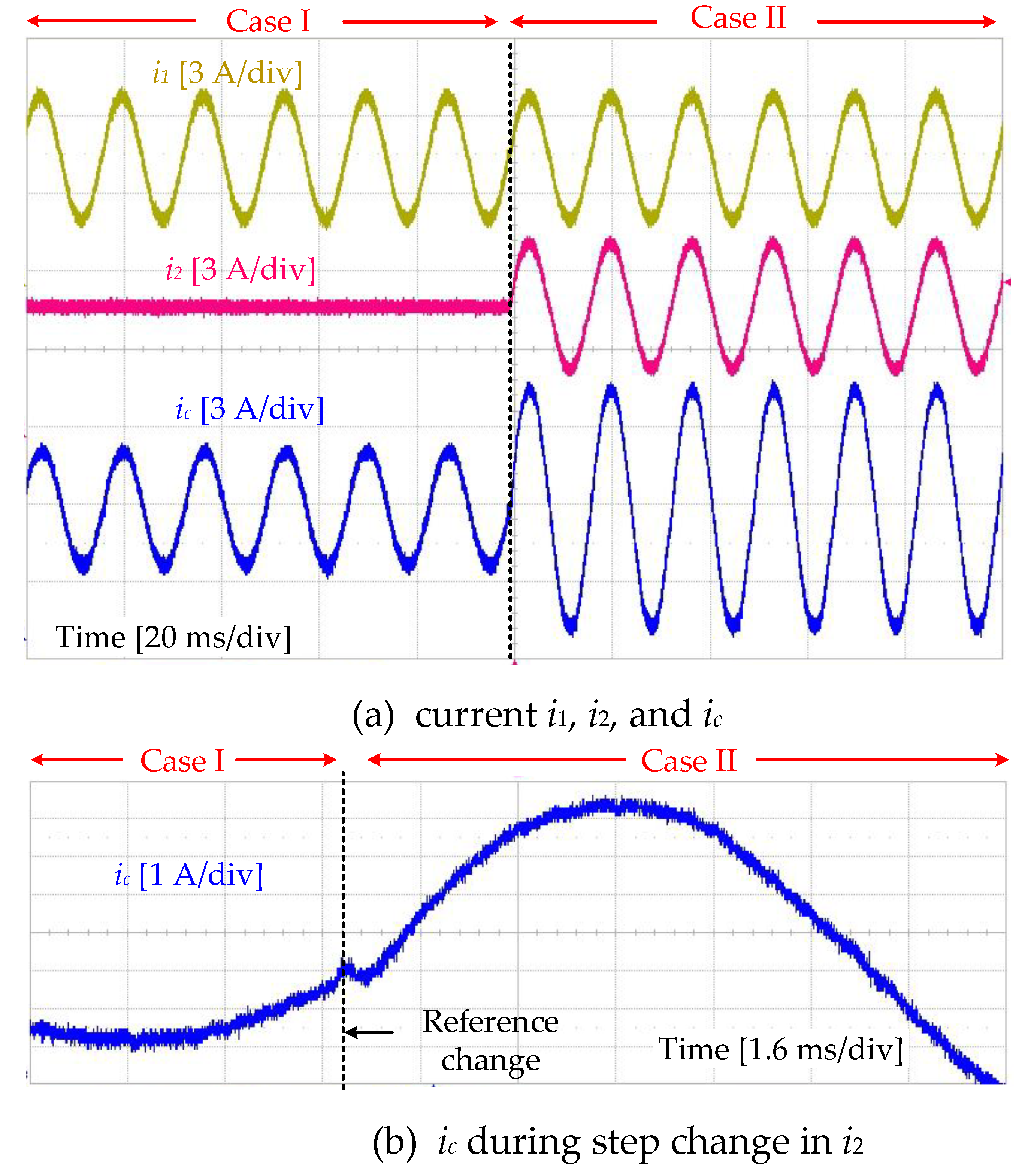
The real-time experimental performance of the proposed scheme during Cases I and II is shown in Figure 12. No mutual current is flowing in i2 when Case I is adopted. In the results, no harmonic oscillation in the steady state is observed in the currents i1, i2 and ic, regardless of the current reference. Additionally, the oscillations in ic during the step change (from Case I to Case II) are removed, which explains the larger stability margin obtained with the proposed scheme, as shown in Figure 12b. Furthermore, the proposed control scheme achieves robust performance with minimum information about the system required without adopting grid voltage feedforward. This theory can also be applied to a system with an uncertain gird impedance or imbalance vpcc.
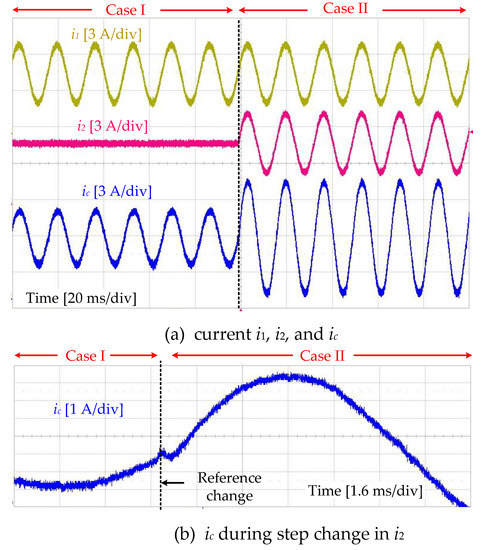
Figure 12.
Experimental results for Cases I and II under the proposed control scheme.
The harmonic analysis using the fast Fourier transform (FFT) for the conventional scheme on i1, i2 and ic is shown in Figure 13a,b for Cases I and II, respectively. The resonance is excited in the common current around fres and fres1, which may result in higher THD of i1 and ic during Case I, as shown in Figure 13a. The THD of i1, i2 and ic is slightly improved during Case II, as shown in Figure 13b.
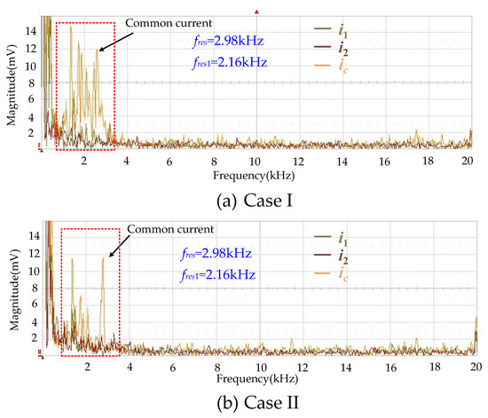
Figure 13.
Harmonic analysis under the conventional scheme presented in [7].
The harmonic analysis using the FFT for the proposed scheme on currents i1, i2 and ic is shown in Figure 14a,b for each case. The harmonics around fres and fres1 are effectively damped for both Case I and Case II. Additionally, the THD of i1, i2 and ic is greatly improved. During Case I, the THD values for i1 and ic measured at the frequency ωg are calculated as 5.02% and 0.65%, respectively. Similarly, the THD values of i1, i2 and ic during Case II are calculated as 4.84%, 4.84% and 0.20%, respectively.
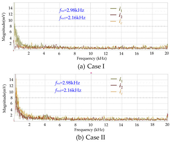
Figure 14.
Harmonic analysis under the proposed scheme.
7. Conclusions
An RESO-based ADRC control scheme is proposed for damping the interactive and common resonances present in LCL filter-type three-phase multi-parallel GCIs regardless of the current reference. The proposed scheme treats the interaction among inverters as an exogenous disturbance caused by other inverters in parallel, estimates it with the RESO, and compensates disturbances in the control law of ADRC. The larger stability margins for the common and mutual current, the preserved disturbance-rejection capabilities under different values of n, and the less model-dependent control design compared to conventional control scheme are the potential benefits of the proposed scheme. The performance of the proposed control scheme was verified and compared with that of the conventional control scheme presented in [7]. A harmonic analysis using the FFT indicates the low THD performance of the proposed method regardless of the current-reference conditions in the system with two parallel GCIs. Thus, the proposed scheme can be extended to a system with an uncertain grid impedance or grid voltage imbalance.
Author Contributions
The individual contribution of each co-author with regards to the reported research writing of the paper is as follows: M.S. conceived the idea, M.S., B.-S.K., S.-H.K. performed the simulation and real-time experimental results. All authors participated in the paper writing.
Funding
This work was supported by “Human Resources Program in Energy Technology” of the Korea Institute of Energy Technology Evaluation and Planning (KETEP), granted financial resource from the Ministry of Trade, Industry & Energy, Republic of Korea. (No. 20184010201710).
Acknowledgments
This work is possible with the support of Higher Education Commission (HEC), Pakistan who supported me financially throughout my journey. I would also like to thank my wife for his moral support.
Conflicts of Interest
The authors declare no conflicts of interest.
Nomenclature
| Superscripts | |
| dq | Quantities in dq reference frame |
| abc | Quantities in abc reference frame |
| * | Reference |
| Subscripts | |
| n | Number of parallel inverters |
| i | Inverter number equal to 1,…, n |
| j | Inverter number equal to 1,…, n and j ≠ i |
| Symbols | |
| eg | Grid voltage |
| Vpcc | Voltage at point of common coupling |
| ii | Inverter-side current of each inverter |
| imi | Mutual current in each inverter |
| ic | Common grid flowing into grid |
| ims | Mutual current summation |
| Vi | Inverter-side voltage of each inverter |
| Vdci and Cdci | DC-link voltage and capacitance of each inverter |
| Z1i, Z2i and Z3i | Inverter-side, grid-side and filter capacitance Impedance |
| Zg (or Lg) | Grid impedance |
| L1, C3, L2 | Inductive, capacitive and inductive components of LCL filter |
| Yii and Yij | Admittance |
| Gplant | LCL filter transfer function |
| Gcoupling | Grid coupling transfer function |
| ωres (or fres) and ωres1 (or fres1) | Interactive and common resonance frequency |
| ωg | Grid fundamental frequency |
| Piref and Qiref | Active and reactive power reference |
| and | Reference of d and q components of current |
| , | Control signal in abc and dq reference frame |
| si1 to si6 | Six pulse gate signals for each IGBT of inverter |
| b | Gain parameter of ADRC |
| β1 and β2 | Observer gains |
| ω0 | Observer Bandwidth |
| Kp | Proportional gain of control |
| Ts | Sampling time |
| x1 and x2 | System states |
| z1i and z2i | Estimated states of ESO |
| f(t) | Lumped disturbances in the system |
| KPWM | PWM gain |
| Gzy | Output-to-estimation transfer function |
| Gzu | Control-to-estimation transfer function |
| Tc and Tm | Loop gain expressions for common and mutual current |
| GM and PM | Gain margin and Phase margin |
| THD | Total Harmonic Distortion |
| Gad | Active damping transfer function |
| Gvc | Inverter-side to capacitor voltage transfer function |
| CPI | PI control transfer function |
Appendix A
The loop-gain transfer functions with conventional derivative filtered capacitor voltage-based active damping representing the common and mutual current stability can be expressed as
and
CPI(s) represents the PI control dynamics in the s-domain and is given as
where kp = ωcL1 and ki = ωc(R1).
The transfer functions Gvc1(z) and Gvc2(z) in Equations (A1) and (A2) relate the inverter-side and LCL filter capacitor voltage as follows:
The transfer function Gad(z) represents a derivative filtered feedforward term in the capacitor voltage loop calculated in the z-domain as
The closed-loop transfer functions Gmut_PI(z) and Gcom_PI(z) representing the mutual and common current can be derived as
References
- Teodorescu, R.; Liserre, M.; Rodriguez, P. Grid Converters for Photovoltaic and Wind Power Systems; John Wiley & Sons: Hoboken, NJ, USA, 2011. [Google Scholar]
- Liserre, M.; Teodorescu, R.; Blaabjerg, F. Stability of photovoltaic and wind turbine grid-connected inverters for a large set of grid impedance values. IEEE Trans. Power Electron. 2006, 21, 263–272. [Google Scholar] [CrossRef]
- Wu, W.; Liu, Y.; He, Y.; Chung, H.S.-H.; Liserre, M.; Blaabjerg, F. Damping methods for resonances caused by LCL-filter-based current-controlled grid-tied power inverters: An overview. IEEE Trans. Ind. Electron. 2017, 64, 7402–7413. [Google Scholar] [CrossRef]
- Enslin, J.H.; Heskes, P.J. Harmonic interaction between a large number of distributed power inverters and the distribution network. IEEE Trans. Power Electron. 2004, 19, 1586–1593. [Google Scholar] [CrossRef]
- He, J.; Li, Y.W.; Bosnjak, D.; Harris, B. Investigation and active damping of multiple resonances in a parallel-inverter-based microgrid. IEEE Trans. Power Electron. 2013, 28, 234–246. [Google Scholar] [CrossRef]
- Lu, M.; Wang, X.; Blaabjerg, F.; Loh, P.C. An analysis method for harmonic resonance and stability of multi-paralleled LCL-filtered inverters. In Proceedings of the 2015 IEEE 6th International Symposium on Power Electronics for Distributed Generation Systems 2015, Aachen, Germany, 22–25 June 2015; pp. 1–6. [Google Scholar]
- Lu, M.; Wang, X.; Loh, P.C.; Blaabjerg, F. Resonance interaction of multiparallel grid-connected inverters with LCL filter. IEEE Trans. Power Electron. 2017, 32, 894–899. [Google Scholar] [CrossRef]
- Wang, X.; Blaabjerg, F.; Liserre, M.; Chen, Z.; He, J.; Li, Y. An active damper for stabilizing power-electronics-based AC systems. IEEE Trans. Power Electron. 2014, 29, 3318–3329. [Google Scholar] [CrossRef]
- Hong, L.; Shu, W.; Wang, J.; Mian, R. Harmonic resonance investigation of a multi-inverter grid-connected system using resonance modal analysis. IEEE Trans. Power Del. 2019, 34, 63–72. [Google Scholar] [CrossRef]
- Akhavan, A.; Mohammadi, H.R.; Guerrero, J.M. Modeling and design of a multivariable control system for multi-paralleled grid-connected inverters with LCL filter. Int. J. Electr. Power Energy Syst. 2018, 94, 354–362. [Google Scholar] [CrossRef]
- Chen, Z.; Chen, Y.; Guerrero, J.M.; Kuang, H.; Huang, Y.; Zhou, L.; Luo, A. Generalized coupling resonance modeling, analysis, and active damping of multi-parallel inverters in microgrid operating in grid-connected mode. J. Mod. Power Syst. Clean Energy 2016, 4, 63–75. [Google Scholar] [CrossRef]
- Lu, M.; Yang, Y.; Johnson, B.; Blaabjerg, F. An interaction-admittance model for multiple-Inverter grid-connected systems. IEEE Trans. Power Electron. 2018, 34, 7542–7557. [Google Scholar] [CrossRef]
- Qian, Q.; Xie, S.; Huang, L.; Xu, J.; Zhang, Z.; Zhang, B. Harmonic suppression and stability enhancement for parallel multiple grid-connected inverters based on passive inverter output impedance. IEEE Trans. Ind. Electron. 2017, 64, 7587–7598. [Google Scholar] [CrossRef]
- Yu, C.; Zhang, X.; Liu, F.; Li, F.; Xu, H.; Cao, R.; Ni, H. Modeling and resonance analysis of multiparallel inverters system under asynchronous carriers conditions. IEEE Trans. Power Electron. 2017, 32, 3192–3205. [Google Scholar] [CrossRef]
- Cavazzana, F.; Caldognetto, T.; Mattavelli, P.; Corradin, M.; Toigo, I. Analysis of current control interaction of multiple parallel grid-connected inverters. IEEE Trans. Sustain. Energy 2018, 9, 1740–1749. [Google Scholar] [CrossRef]
- Yoon, C.; Bai, H.; Beres, R.N.; Wang, X.; Bak, C.L.; Blaabjerg, F. Harmonic stability assessment for multiparalleled, grid-connected inverters. IEEE Trans. Sustain. Energy 2016, 7, 1388–1397. [Google Scholar] [CrossRef]
- Chen, T.; Lee, C.K.; Hui, R. A general design procedure for multi-parallel modular grid-tied inverters system to prevent common and interactive instability. IEEE Trans. Power Electron. 2019, 34, 6025–6030. [Google Scholar] [CrossRef]
- Chen, W.-H.; Yang, J.; Guo, L.; Li, S. Disturbance-observer-based control and related methods—An overview. IEEE Trans. Ind. Electron. 2016, 63, 1083–1095. [Google Scholar] [CrossRef]
- Wang, B.; Xu, Y.; Shen, Z.; Zou, J.; Li, C.; Liu, H. Current control of grid-connected inverter with LCL filter based on extended-state observer estimations using single sensor and achieving improved robust observation dynamics. IEEE Trans. Ind. Electron. 2017, 64, 5428–5439. [Google Scholar] [CrossRef]
- Wang, B.; Shen, Z.; Liu, H.; Hu, J. Linear ADRC direct current control of grid-connected inverter with LCL filter for both active damping and grid voltage induced current distortion suppression. IET Power Electron. 2018, 11, 1748–1755. [Google Scholar] [CrossRef]
- Benrabah, A.; Xu, D.; Gao, Z. Active disturbance rejection control of LCL-filtered grid-connected inverter using Padé approximation. IEEE Trans. Ind. Appl. 2018, 54, 6179–6189. [Google Scholar] [CrossRef]
- Saleem, M.; Choi, K.-Y.; Kim, R.-Y. Resonance damping for an LCL filter type grid-connected inverter with active disturbance rejection control under grid impedance uncertainty. Int. J. Electr. Power Energy Syst. 2019, 109, 444–454. [Google Scholar] [CrossRef]
- Skogestad, S.; Postlethwaite, I. Multivariable Feedback Control: Analysis and Design; Wiley: New York, NY, USA, 2007. [Google Scholar]
- Franklin, G.F.; Powell, J.D.; Workman, M.L. Digital Control of Dynamic Systems; Addison-Wesley: Menlo Park, CA, USA, 1998. [Google Scholar]


© 2019 by the authors. Licensee MDPI, Basel, Switzerland. This article is an open access article distributed under the terms and conditions of the Creative Commons Attribution (CC BY) license (http://creativecommons.org/licenses/by/4.0/).