Abstract
This paper describes modern research methods of the ignition and combustion processes of slurry fuel droplets. The experiments were carried out using a muffle furnace to ensure the conditions of radiation heating, the hot surface to reproduce the conditions of conductive heating, the high-temperature channel with convective heating, the chamber with the processes of soaring, i.e., a significant increase in the time of fuel residence in the combustion chamber. We identified the differences in combustion modes, threshold ignition temperatures, delay times and durations of combustion processes. We obtained the quantitative differences in the characteristics of the ignition and combustion processes for typical registration methods. It was found that for all heating schemes, the minimum ignition temperatures have comparable values. Minimum ignition delay times were recorded during convective heating. The maximum combustion temperatures were achieved with radiation heating. We determined the values of limiting heat fluxes, sufficient to initiate the combustion of slurries fuels during conductive, convective and radiative heating.
1. Introduction
The review articles (in particular, [1,2,3,4,5,6]) devoted to the problems of ignition of composite liquid fuels (CLF) noted that the creation of an adequate and complete theory of sustainable initiation of combustion is difficult due to the small amount of reliable experimental data. A rather narrow group of procedures for the experimental study of the combustion initiation of CLF droplets has been developed [5]. As a result, many processes and effects have not been fully explored yet. An experimental approach based on hanging a droplet (which is like a particle after dehydration of the surface layer) of a fuel composition at the junction of a low-inertia thermocouple and other holders (for example, a thin metal wire (fiber), a metal, phosphor or ceramic rod) is one of the most widely used [7,8,9]. Furthermore, the research methods of the ignition and combustion processes of fuels on a hot surface (substrate) [10] and in a muffle furnace [11,12] are known. Such research was conducted for a single droplet, a small group of fuel droplets, and small volumes of fuel samples. The main advantage of using a low-inertia thermocouple as a holder of a CLF droplet is the ability to control the temperature of the fuel [8]. Another advantage of using the holder is the possibility of continuous registration of the ignition and combustion processes for different fuel compositions with the registration of separate stages (from the evaporation of liquid components, volatile ignition up to the carbon combustion with the ash formation) [5,8].
When comparing experimental values of ignition characteristics of CLF (for example, ignition delay times, durations of stages of the investigated processes, ignition temperatures, etc.), it can be reasonably concluded that ceramic rods, metal wires or thermocouple junctions can lead to changes in conditions of heat transfer in a hanging fuel droplet [13]. When investigating the combustion processes of free-falling droplets of fuel [14,15] (i.e., without using holders), restrictions are imposed due to the short residence time in the combustion chamber.
Owing to the features and limitations identified above, it is advisable to develop an experimental method that ensures a soar of particle (for a single one, small group and a flow of CLF particles) of the fuel composition in a flow of heated air with the ability to control its ignition and combustion processes (using high-speed video recording). The results of studies using a specialized model combustion chamber can be found in [16,17]. It is shown that the conditions of the experiments [16,17] correspond closely to furnaces of thermal power plants, boiler houses, and other power plants, as the fuel particles in them soar after injection into the combustion chamber by the nozzle. The characteristic values of Reynolds numbers can vary from several tens to several hundred, depending on the size of the injected fuel droplets, speeds, and trajectories of their movement, as well as the heating conditions. As a consequence, the values of the Nusselt numbers vary from 2 to 15. Heat-flux density to the fuel droplet surface can reach several tens of kW/m2 in real combustion chambers. It is difficult to implement such conditions using an experimental stand [14,15,16,17] in laboratory experiments. Therefore, laboratories often [15,16,17] focus on experimental research of low-temperature ignition (temperatures in a model combustion chamber up to 700 °C) when droplets move in a combustion chamber at a speed not exceeding 5 m/s. This value corresponds to the almost maximum speed of droplet movement when fuel is injected into the combustion chambers of boiler units of thermal power plants operating on liquid or slurry fuel [17].
The well-known experimental methods, based on CLF pulverization into the combustion chambers [1,2,4], do not allow the integral ignition characteristics of each fuel droplet or a small group of such droplets to be established. This is due to the impossibility of video recording of processes (they are characterized by high speeds at high temperatures, as well as design constraints of the combustion chambers). It is important to understand correctly the contribution of each slurry droplet to the formation of the temperature field in the combustion chamber, as well as the effect of droplets on the heating and ignition of neighboring ones.
The determination of the ignition and combustion characteristics for slurry fuel droplets under different heating conditions is of practical interest for several reasons. Firstly, knowledge of the limiting ignition temperatures, ignition delay times and corresponding heat fluxes is necessary to assess the fire safety of new types of fuels, which include waste-derived slurries. In the case of industrial use of such fuels, the data obtained will allow a safer process to be organized, at the stages of which the studied types of heating are realized (by a hot surface, airflow or by radiation). Secondly, the studied processes and parameters are related to the energy efficiency of the fuel-burning plant. It is important to know what conditions are necessary for the stable ignition of composite liquid fuel with the transition to stationary combustion without flares and loss of flame. These aspects are also important when upgrading existing plants or designing new systems of slurry combustion. They directly affect, in particular, the dimensions of the furnace and the selection and placement of nozzle devices and burners. The third reason is related to issues of fuel substitution and diversification of the fuel base. The established qualitative and quantitative characteristics make it possible to assess the degree of closeness of the studied fuel compositions and other fuels so that they can be used together (for example, with fuel oil and biofuels) in industrial practice without significant restructuring of the technological process. Fourth, it is advisable to use the experimental data to explain the physical mechanisms of the studied processes and their correct description in mathematical modeling. The development of mathematical models is necessary to predict the modes and characteristics of the ignition and combustion of composite liquid fuels over a wider range of conditions and influencing factors.
The aim of this work is to study the differences in the main characteristics of the ignition and combustion processes of slurry fuel particles, obtained using different methods of recording experimental studies and different heating schemes.
2. Typical Nomenclature of Industrial Waste
We used three fuel compositions with different reactivity. Lignite was used as a highly reactive solid component (Borodino mine, Krasnoyarsk Region, Russia). Low-caking coal and coal waste (filter cake with humidity about 40%) of the same coal grade (coal-preparation plant Chernigovskaya-Koksovaya, Kemerovo region, Russia) were used as the less reactive components. Water and waste turbine oil were used as liquid components. Table 1, Table 2 and Table 3 present the main characteristics of the researched components and the prepared fuel slurries. The determination of properties was carried out in a certified laboratory in accordance with international procedures [18,19,20,21,22,23,24,25,26,27] for determining the properties of solid and liquid combustible materials.

Table 1.
Characteristics of solid combustible components.
Table 2.
Characteristics of used turbine oil.
Table 3.
Investigated fuel slurries.
3. Experimental Setup and Methods
3.1. Heating of the Fuel Particles on the Hot Surface
An experimental approach based on the heating of a fuel sample on a metal surface is often used to study the ignition and combustion of liquid fuels (for example, oil products). In the present work, we used a metal substrate to study the ignition and combustion processes of CLF droplets. The substrate was preheated to high temperatures with an induction heater (Figure 1). This heating scheme, in general, simulates the fuel-bed combustion of solid and slurry fuels. It should be noted that using these technologies requires significant consumption of energy for efficient combustion (that is, with minimal underburning) of the above-listed fuels. In the case of flame combustion of CLF, the probability of sticking of fuel particles to the walls of the combustion chamber is high, which is also characteristic of fuel combustion on a heated substrate.
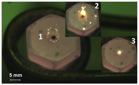
Figure 1.
Video frames of the slurry fuel (composition #3) droplet combustion on a heated metal substrate (heating temperature is 600 °C): 1—the moment of initial contact with the heated surface, 2—ignition, 3—combustion.
3.2. Heating of a Fuel Particle on the Holder in the Flow of Heated Air
The study of the ignition processes of a CLF droplet suspended at the junction of a low-inertia thermocouple (Figure 2) in a flow of heated air is widespread throughout the world. In addition, holders are used made from various materials, such as thin metal wires, ceramic rods, quartz fibers. The processes of heating, ignition, and combustion are recorded using a video camera. This approach is considered practical and convenient and is often used for studying the combustion behavior of fuels in different conditions [28]. It should be noted that different holders can lead to changes in the heat transfer conditions in a CLF droplet suspended on them, for example, they can increase the heat sink to the holder from the droplet surface or an additional heat flux through the holder to the fuel.
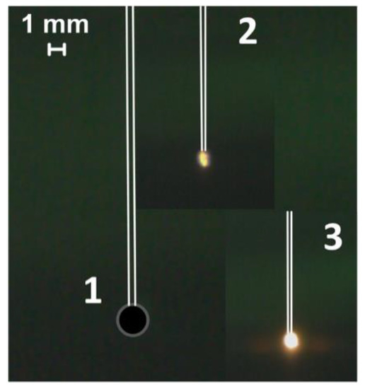
Figure 2.
Video frames of the slurry fuel (composition #2) droplet combustion in a heated air flow at the junction of a thermocouple (heating temperature is 600 °C, flow rate is 3 m/s): 1—the moment of initial contact with the heated medium, 2—ignition, 3—combustion.
3.3. Heating of the Fuel Particle in the Conditions of Intense Radiation Heating on the Holder
Heating the fuel under conditions of radiative heat transfer is one method among others used to study ignition and combustion processes. A muffle furnace with a ceramic cylinder is used for this method implementation, where, on the one hand, a fuel droplet on the holder is introduced (Figure 3), and on the other hand, high-speed video recording is performed. This method allows a more detailed fixation of the gas-phase ignition stage for the CLF droplet since there is no airflow. However, the lack of oxygen supply can lead to a change in the time characteristics of the fuel solid part ignition.
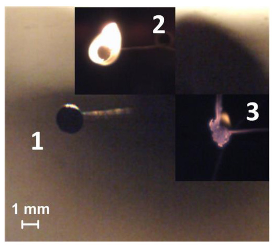
Figure 3.
Video frames of the slurry fuel (composition #2) droplet combustion under conditions of radiation heating (heating temperature is 600 °C): 1—the moment of initial contact with the heated medium, 2—ignition, 3—combustion.
3.4. Use of a Quartz Combustion Chamber
Droplets and particles of fuel soar constantly move and burn out in the combustion space in real conditions. Therefore, we performed experiments with the combustion initiation of the CLF in a flow of heated air based on the developed model, a transparent combustion chamber (Figure 4). The geometry of the combustion chamber allowed us to approach the conditions of particle soaring in real furnaces of boilers and, at the same time, to observe the movement of particles due to its transparency. Quartz glass as a blow heater has a temperature limit (maximum temperature is 730 °C). It is possible to predict time characteristics by extrapolating the curves for higher temperatures, as well as to conduct experiments at the limiting air temperatures corresponding to the operating temperature of quartz glass (no more than 1027 °C).
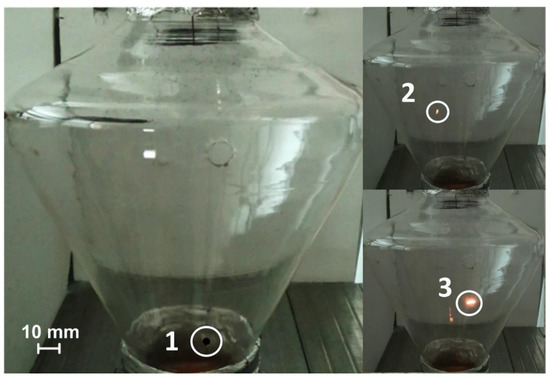
Figure 4.
Initiation of combustion of a souring CLF droplet in a flow of heated air (Vg ≈ 4 m/s) at the cone-shaped channel inlet: 1—the moment of the droplet falling; 2—ignition; 3—combustion.
Figure 1, Figure 2, Figure 3 and Figure 4 present video frames of CLF droplets from the moment they are placed in an oxidizing environment (1), ignition (2) and combustion (3) for each experimental method described above. We recorded the investigated processes of ignition initiation of CLF droplets using the high-speed video camera Phantom Miro M310 11 (maximum shooting speed of 3260 fps at full definition of 1280 × 800 pixels). The change of a CLF droplet temperature during its heating and combustion was monitored using a system consisting of a National Instruments 9213—high-speed data acquisition system and a low-inertia thermocouple (platinum to platinum/rhodium thermocouple, measured temperature range 0–1600 °C, error ±1 °C, inertia 0.1 s, junction diameter 0.1 mm).
The determination of the desired parameters was carried out by repeatedly reproducing the experiment under constant conditions and related measurements. Therefore, it was necessary to analyze the measurement results by eliminating gross errors and assessing the boundaries of the confidence interval. Figures with experimental data are provided with confidence intervals that illustrate the range of potential values of the parameter. This range includes the true value of the parameter with a given probability (in this paper it is assumed to be 95%). For the analysis, well-known processing approaches [29] of data that follow the normal distribution were used. The processing algorithm included the following steps. After eliminating gross errors, the expected value was determined (as the arithmetic mean). Then, the measure of the spread of the random variable relative to the expected value was determined (the variation coefficient was calculated). Knowing the variation coefficient, the standard deviation of the random variable was calculated. At the final stage, it was necessary to determine the width of the confidence interval, knowing the confidence probability (95%) and the number of measurements (this parameter varied).
4. Results and Discussion
4.1. Stages of Fuel Ignition and Combustion with Different Heating Schemes
Several features characterize each method (Figure 1, Figure 2, Figure 3 and Figure 4) of the combustion initiating of the CLF droplets. They are determined mainly by the composition of the fuel, the properties of its components and the temperature. Figure 5a shows the frames of gas-phase ignition and fiery combustion of CLF based on filter cake of low-caking coal and waste turbine oil in a muffle furnace (Tg ≈ 600 °C). We recorded dispersion effects (Figure 5b) during the ignition and combustion of a slurry droplet of CLF based on lignite, water, and waste turbine oil, which are mainly due to the high content of volatile of lignite. Dispersion increases with increasing airflow temperature. We observed the same effect when initiating the combustion of CLF droplets on a heated metal substrate (for the composition with low-caking coal and the addition of lignite) (Figure 5c). Detection of the boundaries of the ignition and combustion stages of the soar CLF particle (Figure 5d) in a swirling flow of heated air is more complicated since the fuel particle is constantly moving in different parts of the model combustion chamber.
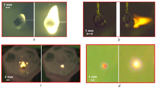
Figure 5.
Modes of CLF droplet ignition and combustion with the different heating schemes (Tg ≈ 600 °C): (a)—in a muffle furnace with a droplet holder; (b)—in a heated air flow with a droplet holder; (c)—on a heated metal substrate; (d)—in the soaring mode in a heated air flow.
The physical and chemical processes, occurring during heating a CLF droplet, may also proceed in a smoldering combustion mode. We observe this mode when the heating temperature is lower than the minimum temperature of the fuel ignition. If it is the smoldering combustion mode, the processes of volatile release and evaporation of the liquid fuel component are not accompanied by intense oxidation. The flame burning is very weak or completely absent, and the luminescence of the fuel sample is recorded.
Flame combustion mode (Figure 5a presents a typical frame) was recorded in most of the conducted experiments when the temperature of the heating medium exceeded the ignition temperature of a particular fuel. The addition of a flammable liquid to the slurry, for example, high calorific value petroleum products, facilitates the flaming combustion. These components evaporate and burn in the gas phase when they are heated. This contributes to the formation of a large, stable flame (Figure 5a) when burning slurry fuel with the addition of a liquid combustible component.
The effects of a micro-explosion with the diffusion of vapors of liquid components into the environment are realized under conditions of high-temperature heating of slurry fuel droplets. These effects are largely caused by different temperatures, heat, rates of evaporation and boiling of the oil component and water. Overheating of water vapor, oil product and volatiles leads to a growth of pressure in the droplet and subsequent sudden emissions of gaseous products through the pores of the droplet. In this case, the solid particles disperse and we observe the effect of micro-explosions.
4.2. Minimum Temperatures of Combustion Initiation
Figure 6 shows the established differences in the minimum temperatures of the heated medium (air, surface), which ensure the ignition of the CLF droplets using all four research methods. The minimum (threshold) ignition temperatures for the studied compositions ranged from 270 to 560 °C (Figure 6) when we used different heating schemes. The maximum difference (≈70 °C) was registered for slurry based on the filter cake of low-caking coal and used turbine oil when comparing the obtained results with conductive and convective heating. The highest ignition temperatures (490–560 °C) also characterize this composition in comparison with other slurries (Figure 6), since the base component (filter cake) is waste and contains ash (about 50%) in the solid part (Table 1), which is not conducive to the realization of the ignition conditions with a decrease in the heating temperature. Lower ignition temperatures (270–340 °C) are typical for slurries based on bituminous and lignite coals (compositions #2 and #3) using all heating schemes (Figure 6). It should also be noted that lignite, used as the main component of the slurry, promotes an increase in its reactivity at lower heating temperatures. Primarily, this is due to a high concentration of volatiles in lignite. Volatiles mix with vapors of a combustible liquid (waste turbine oil) and form a chemically reactive combustible gas mixture capable of igniting at relatively low oxidizer temperatures. Additional thermal energy is released during the gas-phase combustion of the mixture, which heats the solid residue of the fuel and intensifies its heterogeneous ignition.
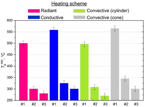
Figure 6.
Threshold (minimum) temperatures of ignition of CLF droplets (Rd ≈ 0.6 mm) with different heating scheme.
4.3. Ignition Delay Times
The ignition delay time (τd) of fuel is one of the determining parameters of the efficiency of CLF combustion. It characterizes the inertia of the combustion initiation process and depends on a number of determining factors (temperature, droplet size, fuel properties, etc.). It is expected that the ignition delay time decreases for all fuel compositions and all methods of heat supply (Figure 7) if heating temperature increases, because the processes of heating, dehydration, oil evaporation, and thermal decomposition of the solid slurry component intensify with an increase in heat flow. When varying the temperature from 570 to 630 °C, the ignition delay times decrease by 20–40% on average (Figure 7).
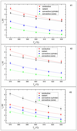
Figure 7.
Ignition delay times of CLF droplets (Rd ≈ 0.6 mm) at different temperatures and heating schemes. Fuel compositions #1–3 from Table 3.
The ignition of the soaring CLF droplets is faster by 25–35% compared to droplets suspended statically in a flow of heated air. The minimum values of τd correspond to the soaring mode, in which convective heat transfer is maximized due to the most complete flow of heated air around a moving particle. Maximum ignition delay times are recorded during radiation heating of the fuel in a muffle furnace. This may be due to the lack of oxygen supply to the surface of the fuel under such conditions. A buffer layer (a mixture of water vapor and air) is created around the droplet, it prevents the heating up of the deep layers of a droplet and limits the access of oxygen to the coke residue already at the stage of homogeneous combustion of the gaseous components of fuel. In the case of conductive heat transfer, the τd value is lower by 15–18% relative to the radiation (Figure 7). This is probably because heat transfer efficiency increases when there is direct contact of a fuel droplet with a hot surface, because of a decrease in the thickness of the air-vapor layer between the heating source and the combustible mass.
Droplet size is one of the key parameters affecting the characteristics of the ignition and combustion of liquid or slurry fuel. It is very important to understand the scale and nature of the droplet size effect on the main characteristics of their ignition and combustion for the development of effective ignition and combustion technologies for the investigated fuels. This background knowledge is necessary for the development of nozzles required for the implementation of the flame combustion of slurry fuels.
Figure 8 shows the effect of the initial size of the fuel droplets on the inertia of the ignition. It is easy to see that the ignition delay time increases with increasing droplet size for all studied fuels, because the heat consumption for endothermic evaporation and decomposition processes increases in the case of larger fuel droplets. Furthermore, the heat sink intensifies to the deep layers of the slurry droplet, which leads to a decrease in the rate of the temperature growth of the slurry droplet surface during the heating process. In the experiments, the ignition delay times increased on average by a factor of 1.8–2.2 with conductive heating, 1.5–3.2 with convective heating, and 1.5–2 with radiative heating when the initial radius of the droplet changes from 0.4 mm to 0.75 mm (Figure 8).
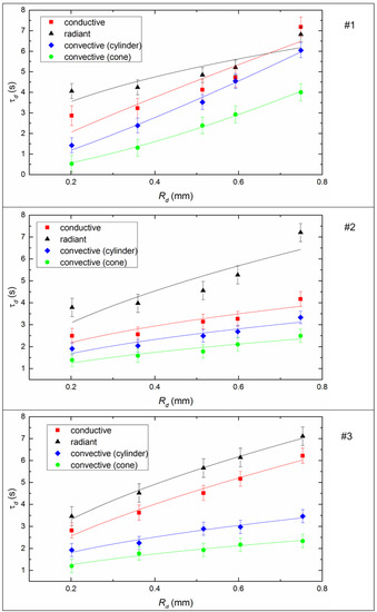
Figure 8.
Ignition delay times of CLF droplets depending on their initial dimensions (Tg ≈ 600 °C, Vg ≈ 3.5 m/s) by varying the heating scheme. Fuel compositions #1–3 from Table 3.
In this work, the conditions of the experiment and the limitations of the installation influenced the choice of the size range of the droplets of the slurry. The main goal of this study was to analyze the possible differences in the combustion parameters for different heating schemes, but with a further decrease in droplet size (Rd < 0.2 mm), the processes proceed very quickly and it becomes quite difficult to determine the required characteristics. For this reason, most likely, most researchers use the range 1 ≤ Rd ≤ 2 mm [30,31,32] to detail experiments with drops of fuel mixtures.
When considering the results in the context of practical applications, several points should be noted. If we consider the technology of burning a fuel slurry using nozzles, then, most likely, the droplet size will vary over a fairly wide range. This is because the jet of slurry through the nozzle cannot be very thin, as this will lead to rapid mechanical wear or require ultra-fine grinding of solid particles. Accordingly, obtaining a homogeneous cloud of small droplets is difficult. Therefore, the results for larger droplets can rightfully be used for practical applications as an upper estimate for the ignition and combustion parameters. For example, there is reason to believe that when burning the fuels under consideration in large furnaces, the ignition delay times will not exceed the values set in this study (since the holder will not influence, convective heating will influence, and the accumulating self-heating effect will appear when a large amount of fuel is ignited). The established minimum ignition temperatures are likely to be valid for combustion conditions in the boiler. These data are quite important for practical applications since they allow us to estimate, when planning full-scale tests and industrial implementation, the placement of nozzle devices and burners, the distances between the walls of the combustion chamber to ensure fuel ignition before colliding with surfaces, etc. Thus, it is possible to use the obtained results in relation to the combustion conditions in boilers, even under the conditions of droplet size limitations. However, the development of the present study, of course, is possible precisely in the direction of obtaining data on the scale and conditions close to industrial heat power engineering.
It should also be noted that the obtained experimental results can be used to predict the characteristics of the ignition and combustion of fuels in the range of values that are characteristic of industrial combustion chambers. All the curves given in the article are characterized by the preservation of monotony in the studied range of temperatures and droplet sizes. Therefore, there is every reason to legitimately extrapolate the values of the studied characteristics to a wider range of temperatures and initial sizes of fuel droplets.
It is important to determine the duration of the fuel combustion since this parameter directly affects the fuel consumption, maintenance of the combustion medium temperature and the design features of the boiler units. Figure 9 illustrates the heating temperature impact on the duration of the complete combustion of the slurry droplets of different compositions. A decrease in the combustion time (on average by 15–35%) is registered with an increase in the heating temperature in most experiments (Figure 9). However, we recorded an increase in the combustion duration by 20–35% for the compositions based on the filter cake (#3, Table 3) and coal (#2, Table 3) under conditions of radiant heat transfer (in a muffle furnace) with an increase in temperature from 570 to 630 °C. This is probably because the coke part of these fuels burns out more intensively as the temperature increases, and as a result, the combustion duration increases. This effect is not observed for the composition based on lignite (#3, Table 3). Dispersion effects and high reactivity are typical for this fuel. This leads to fragmentation of the initial droplet at the combustion stage and, as a consequence, a decrease in the combustion duration. The duration of combustion for different fuels differs, on average, by 50–60% if we vary the method of heat supply (Figure 9). The fuel burns faster with the convective heating, and slower with the radiation heating.
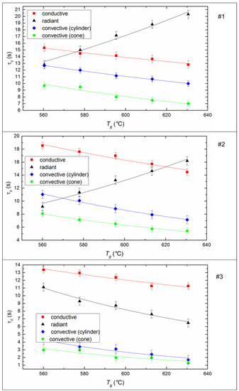
Figure 9.
Time of complete combustion of CLF droplets (Rd ≈ 0.6 mm) at different temperatures and heating schemes. Fuel compositions #1–3 from Table 3.
To provide more accurate estimates of the heat flux effect (q) under conditions of convective (with and without a holder), conductive and radiative heating on the ignition characteristics of a CLF droplet, appropriate calculations were performed with plotting (Figure 10). We used the following expressions to calculate heat flow values:
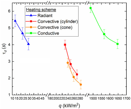
Figure 10.
Ignition delay times for a CLF droplet (40% of bituminous coal, 10% of lignite, 40% of water, 10% of used turbine oil), depending on the heat flux for different heating schemes.
Using the values of physical quantities (τd, Rd, Tg, Vg, etc.) and the thermophysical characteristics of a CLF droplet, we obtained the values of the ignition delay times depending on the change in the heat flux for each heating scheme. According to experimental data and the corresponding theoretical estimates (Figure 10), the rate of decrease in the ignition delay times varies with increasing heat flux supplied to the fuel using different methods. In particular, the highest rate of decrease in the ignition delay time is typical to the radiation heating (Figure 10). In this case, τd decreases by 20–26% when the heat flux varies from 28 to 37 kW/m2 (Figure 10). The values of τd decrease by 40–45% during convective heating of a fixed fuel droplet in a cylindrical channel and with a variation of the heat flux from 188 to 219 kW/m2 (Figure 10). The values of τd decrease by 45–50% during convective heating of the soaring droplet of slurry in the model combustion chamber, when the heat flux is varied from 196 to 229 kW/m2 (Figure 10).
Figure 10 illustrates that it is necessary to supply different amounts of heat flux to the fuel to achieve the same ignition time when using different heating schemes. In particular, to provide the value τd ≈ 4 s the heat flux is about 33 kW/m2 in the muffle furnace, it is about 188 kW/m2 with convective heating of a fixed droplet in the cylinder, and it is about 1647 kW/m2 with conductive heating on a hot surface. Thus, we can conclude that the radiation is most attractive to accelerate the initiation of fuel combustion heating in terms of energy savings. The local (conductive) heat supply is the least effective from this point of view (Figure 10). However, in terms of fire safety, this approach has a great advantage. Unregulated fuel combustion (most common for pulverized coal or other dry fine fuel [33]) at thermal power plants or boiler houses may occur due to the contact with heated surfaces (for example, parts of mechanisms). Based on the results of the assessments (Figure 10), it can be concluded that the ignition is most difficult with the conductive heat supply to a fuel. At the same time, a thin surface layer of the ash encrust is formed in the contact zone between the hot surface and the fuel, which leads to a decrease in the intensity of oxidation reactions.
4.4. Maximum Combustion Temperatures of Fuel
Heat release during fuel combustion is one of the important parameters in the calculation of heat transfer in the furnace. Heat release during combustion of slurry fuel can be estimated experimentally by measuring the temperature of a fuel droplet during its combustion. The determination of the influence of the heat supply method to the fuel on the dynamics of change in its combustion temperature is of interest in this work (Figure 11). It is clear from the results of the experiments that the processes of ignition and combustion are the least inertial in the convective method of heat supply. The dynamics of changes in the temperature of the fuel droplet during heating are quite similar to that during the radiation and conductive processes of heat supply (Figure 11). However, higher combustion temperatures (≈770 °C) are achieved when the fuel is heated in a muffle furnace, despite the large inertia of ignition. This suggests a deeper burnout of the coke part of the CLF particle under conditions of the dominance of radiant heat transfer. On average, the differences in the maximum combustion temperatures are about 60 °C with the varying heating schemes.
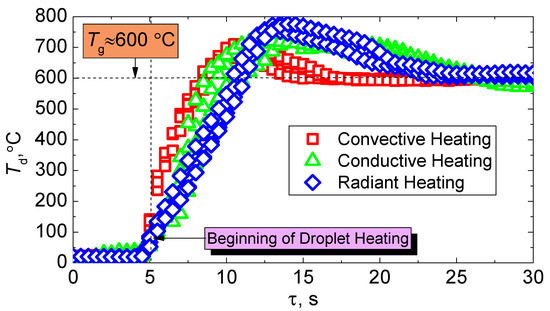
Figure 11.
Change in temperature of a CLF droplet (40% of bituminous coal, 10% of lignite, 40% of water, 10% of used turbine oil) using various heating schemes.
We recorded sufficiently low values of the maximum combustion temperatures during convective heating (Figure 11). There are two main reasons for this. Firstly, the effects of dispersion are enhanced by the air flow in leakage. This affects the combustion temperature recorded by a thermocouple installed in the fuel sample, even if the amount of separated particles is small. Secondly, the heat sink to the environment in the existence of air flow contributes to the cooling of the fuel sample and, as a consequence, to a decrease in Tdmax.
4.5. Anthropogenic Emissions
The possibility of significant impoverishment of hazardous substances in the combustion products (primarily sulfur and nitrogen oxides) is one of the key advantages of using water-saturated slurry fuels in thermal power engineering. We used a standard procedure described in [6] to record the concentrations of sulfur and nitrogen oxides in the combustion products of different composition fuels (Table 3) and the sample weight of fuel burned in a muffle furnace. Combustion products were collected using a gas analyzer probe.
Figure 12 shows the influence of temperature in the combustion chamber on the concentrations of sulfur and nitrogen oxides released during the combustion of the investigated fuels. Emissions of hazardous substances increase when the temperature is varied from 700 to 1000 °C (Figure 12), since temperature increase promotes acceleration of physicochemical processes, including oxidation of sulfur and nitrogen compounds in fuel and oxidation of nitrogen contained in the air. If the temperature varies from 700 to 1000 °C in the muffle furnace, the concentration of SOx increases, on average, by 1.5–2.5 times (Figure 12a). The most noticeable increase in SOx emissions is characteristic of the CLF composition based on lignite. When it burns at Tg ≈ 1000 °C, SOx is produced 18–24% more than when the other two studied fuels (Figure 12a) combust. The sulfur content of the fuel components (Table 1) determines the emissions of sulfur oxides during combustion except for external factors (temperature, excess air, etc.). Used bituminous coal contains a small amount of sulfur (Table 1) in comparison with other components. However, lignite and filter cake have comparable sulfur content. Therefore, the high oxygen content in lignite is the reason for the high emissions of SOx in the combustion products of the slurries based on lignite (Table 1). The oxygen content in the lignite is several times higher than in the filter cake. Oxygen contributes to the oxidation of sulfur compounds and a corresponding increase in the concentration of SOx in the combustion products.
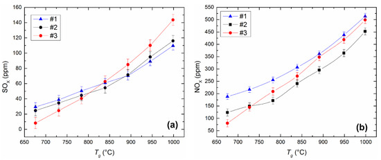
Figure 12.
Dependences of SOx (a) and NOx (b) concentrations on the heating temperature during the combustion of the CLF compositions in a muffle furnace (radiation heat exchange). Fuel compositions #1–3 from Table 3.
Figure 12 illustrates the dependences of NOx emissions on the temperature in the combustion chamber during the combustion of different compositions of CLF. The concentration of NOx in the combustion products of the studied slurries increases on average by 1.3–1.7 times with an increase in temperature in the combustion chamber (Figure 12b). The greatest emissions among the considered slurries are characteristic of fuel based on filter cake. The concentration of NOx in the combustion products of this fuel exceeds the similar parameter of other slurries on average from 8% to 35% in the range of temperature variation of 700 to 1000 °C (Figure 12b). However, in general, we can conclude that NOx emissions are comparable for all studied compounds—the deviation of NOx concentrations for different compositions averaged 65–100 ppm.
4.6. Analysis of the Ash Residue during Fuel Combustion
We present the results of the analysis of mechanical underburning for three methods among all those used for heating fuel droplets. There are certain difficulties in the capture of soaring burned-out ash particles related to their entrainment through the exhaust duct into the atmosphere. Therefore, we do not present the results for the method of soaring particles and their unburned residues. Figure 13 shows that the minimum fuel underburning corresponds to the method of radiation heating for all studied compositions from 8% to 15%. This indicates the maximum efficiency of fuel combustion during radiation heating with a minimum heat sink from the exothermic reaction zone. The underburning of fuel is higher for the other combustion initiation schemes since the presence of intense heated airflow or heated surface (up to 60%) leads to heat sink from the CLF particle.
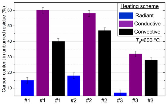
Figure 13.
The proportion of carbon contained in the unburned residue of droplets of the studied CLF compositions with different heating schemes. Fuel compositions #1–3 from Table 3.
The results of the experiments are a fundamental experimental basis for assessing the adequacy of ignition and combustion models for promising slurry fuels (for example, [33]), developed to study the characteristics and conditions for initiating these processes with prepotency of different mechanisms of energy supplying to the fuel, in particular, convective, conductive, radiation or mixed. Therefore, the established numerical values of the ignition delay times, extreme ignition initiation temperatures and maximum combustion temperatures can be used to analyze the completeness of the processes, effects and factors in modern models of ignition and combustion of promising slurry fuels.
5. Conclusions
- (i)
- All of the considered heating schemes can be used to study the ignition and combustion of slurry fuels (with the dominance of the conductive, convective and radiation mechanisms). The differences in the basic characteristics of the heating, ignition and combustion established during the experiments make it possible to predict similar differences for real combustion processes. The mechanism of the slurry fuel droplet ignition is common and based on intensive dehydration of the surface layers of fuel fragments, the formation and ignition of the gas-vapor mixture (volatile and vapors) and the subsequent heterogeneous ignition of the carbon base.
- (ii)
- Based on a comparative analysis, it can be concluded that the most effective in terms of minimizing the ignition delay times and the extreme temperatures of combustion initiation is convective heating of the fuel. The maximum combustion temperatures and the minimum ash residue, consequently, correspond to the experiments with radiation heating. We can ensure such conditions by organizing vortex combustion processes in which fuel droplets spin in the combustion chamber and burn out for a long time. The completeness of fuel underburning is reduced, and anthropogenic emissions are minimized.
- (iii)
- According to the properties and concentration of the slurry fuel components, as well as the method for their heating, there are three possible modes of ignition and combustion of slurry fuel particles: flame, smoldering and micro-explosion. As a result, the ignition delay times, the extreme temperatures of the ignition and especially the temperature and duration of the slurry combustion may be different. The obtained experimental data on the characteristics and conditions for the implementation of these processes allow us to explain the differences of the parameters considered in the present work, which are recorded by various scientific groups throughout the world.
Author Contributions
P.S. wrote the paper; T.V. and K.V. performed the experiments.
Funding
The research was supported by a grant from the President of the Russian Federation (MD–314.2019.8).
Conflicts of Interest
The authors declare no conflict of interest.
Abbreviations
| CLF | composite liquid fuels |
| Nomenclature | |
| Ad | ash level of dry sample (%) |
| Ca | heat capacity of air (J/(kg K)) |
| Cdaf, Hdaf, Ndaf, Odaf | fraction of carbon, hydrogen, nitrogen, oxygen in the sample converted to a dry ash-free state (%) |
| NOx | concentration of nitrogen oxides (ppm) |
| Q | heat flux (kW/m2) |
| qcond | conductive heat flux (kW/m2) |
| qconv | convective heat flux (kW/m2) |
| qrad | radiative heat flux (kW/m2) |
| Qas | heat of combustion (MJ/kg) |
| Rd | initial droplet radius (mm) |
| Std | fraction of sulfur in the sample converted to a dry state (%) |
| SOx | concentration of sulfur oxides (ppm) |
| Td | temperature in the center of a droplet (°C) |
| Tdmax | maximum temperature in the center of a droplet (°C) |
| Tg | temperature in combustion chamber (°C) |
| Tgmin | minimum heating temperature sufficient for sustainable ignition (°C) |
| Ts | droplet surface temperature (°C) |
| Tsub | heated substrate temperature (°C) |
| Vdaf | yield of volatiles of filter cake converted to a dry ash-free state, (s) |
| Vg | gas flow velocity (m/s) |
| Wa | initial sample moisture (%) |
| Greek symbols | |
| A | heat transfer coefficient (W/(m2·K)) |
| εd | emissivity factor of water droplet |
| εa | emissivity factor of air |
| Λ | thermal conductivity (W/(m·K)) |
| λd | thermal conductivity coefficient of water droplet (W/(m·K)) |
| λa | thermal conductivity coefficient of air (W/(m·K)) |
| νa | kinematic viscosity of air (m2/s) |
| ρa | air density (kg/m3) |
| σ | Stefan‒Boltzmann constant (W/(m2·K4)) |
| τd | ignition delay time (s) |
| τc | time of complete burnout (s) |
| Dimensionless numbers | |
| Nu | Nusselt number |
| Pr | Prandtl number |
| Re | Reynolds number |
References
- Gorlov, E.G. Composite water-containing fuels from coals and petroleum products. Solid Fuel Chem. 2004, 38, 40–50. [Google Scholar]
- Khodakov, G.S. Coal-water suspensions in power engineering. Therm. Eng. 2007, 54, 36–47. [Google Scholar] [CrossRef]
- Lishtvan, I.I.; Falyushin, P.L.; Smolyachkova, E.A.; Kovrik, S.I. Fuel suspensions based on fuel oil, peat, waste wood, and charcoal. Solid Fuel Chem. 2009, 43, 1–4. [Google Scholar] [CrossRef]
- Vedruchenko, V.R. The dynamics of droplet transformations in the flame of a water-fuel oil emulsion used as the fuel for boiler installations. Therm. Eng. 2000, 47, 156–160. [Google Scholar]
- Glushkov, D.O.; Strizhak, P.A.; Chernetskii, M.Y. Organic Coal-Water Fuel: Problems and Advances (Review). Therm. Eng. 2016, 63, 707–717. [Google Scholar] [CrossRef]
- Dmitrienko, M.A.; Strizhak, P.A. Coal-water slurries containing petrochemicals to solve problems of air pollution by coal thermal power stations and boiler plants: An introductory review. Sci. Total Environ. 2018, 613–614, 1117–1129. [Google Scholar] [CrossRef] [PubMed]
- Gajewski, W.; Kijo-Kleczkowska, A.; Leszczynski, J. Analysis of cyclic combustion of solid fuels. Fuel 2009, 88, 221–234. [Google Scholar] [CrossRef]
- Kijo-Kleczkowska, A. Combustion of coal-water suspensions. Fuel 2011, 90, 865–877. [Google Scholar] [CrossRef]
- Singh, G.; Esmaeilpour, M.; Ratner, A. Investigation of combustion properties and soot deposits of various US crude oils. Energies 2019, 12, 2368. [Google Scholar] [CrossRef]
- Wu, D.; Song, Z.; Schmidt, M.; Zhang, Q.; Qian, X. Theoretical and numerical study on ignition behavior of coal dust layers on a hot surface with corrected kinetic parameters. J. Hazard. Mater. 2019, 368, 156–162. [Google Scholar] [CrossRef]
- Wang, H.; Liu, S.; Wang, X.; Shi, Y.; Qin, X.; Song, C. Ignition and Combustion Behaviors of Coal Slime in Air. Energy Fuels 2017, 31, 11439–11447. [Google Scholar] [CrossRef]
- Chen, G.B.; Chatelier, S.; Lin, H.T.; Wu, F.H.; Lin, T.H. A Study of Sewage Sludge Co-Combustion with Australian Black Coal and Shiitake Substrate. Energies 2018, 11, 3436. [Google Scholar] [CrossRef]
- Vershinina, K.Y.; Egorov, R.I.; Strizhak, P.A. The ignition parameters of the coal-water slurry droplets at the different methods of injection into the hot oxidant flow. Appl. Therm. Eng. 2016, 107, 10–20. [Google Scholar] [CrossRef]
- Atal, A.; Levendis, Y.A. Observations on the combustion behavior of coal water fuels and coal water fuels impregnated with calcium magnesium acetate. Combust. Flame 1993, 93, 61–89. [Google Scholar] [CrossRef]
- Atal, A.; Levendis, Y.A. Combustion of CWF agglomerates from pulverized or micronized bituminous coal, carbon black, and diesel soot. Combust. Flame 1994, 93, 326–342. [Google Scholar] [CrossRef]
- Bogomolov, A.; Valiullin, T.; Vershinina, K.; Shevyrev, S.; Shlegel, N. Igniting Soaring Droplets of Promising Fuel Slurries. Energies 2019, 12, 208. [Google Scholar] [CrossRef]
- Valiullin, T.R.; Strizhak, P.A. Influence of the shape of soaring particle based on coal-water slurry containing petrochemicals on ignition characteristics. Therm. Sci. 2017, 21, 1399–1408. [Google Scholar] [CrossRef]
- ISO. Solid Mineral Fuels—Hard Coal—Determination of Moisture in the General Analysis Test Sample by Drying in Nitrogen; ISO 11722:1999; International Organization for Standardization ISO Central Secretariat: Geneva, Switzerland, 1999. [Google Scholar]
- ISO. Solid Mineral Fuel—Determination of Ash; ISO 1171:2010; International Organization for Standardization ISO Central Secretariat: Geneva, Switzerland, 2010. [Google Scholar]
- ISO. Hard Coal and Coke—Determination of Volatile Matter; BS ISO 562:2010; International Organization for Standardization ISO Central Secretariat: Geneva, Switzerland, 2010. [Google Scholar]
- ISO. Solid Mineral Fuels—Determination of Gross Calorific Value by the Bomb Calorimetric Method and Calculation of Net Calorific Value; ISO 1928:2009; International Organization for Standardization ISO Central Secretariat: Geneva, Switzerland, 2009. [Google Scholar]
- ASTM. Standard Test Method for Heat of Combustion of Liquid Hydrocarbon Fuels by Bomb Calorimeter; D240-92 (1997) e2; ASTM International: West Conshohocken, PA, USA, 2000. [Google Scholar]
- ISO. Petroleum Products and Bituminous Materials: Determination of Water—Distillation Method; ISO 3733:1999; International Organization for Standardization ISO Central Secretariat: Geneva, Switzerland, 1999. [Google Scholar]
- ISO. Petroleum Products: Determination of Ash; ISO 6245:2001; International Organization for Standardization ISO Central Secretariat: Geneva, Switzerland, 2001. [Google Scholar]
- ISO. Petroleum Products: Determination of Flash and Fire Points—Cleveland Open Cup Method; ISO 2592:2000; International Organization for Standardization ISO Central Secretariat: Geneva, Switzerland, 2000. [Google Scholar]
- ASTM. Standard Test Methods for Determination of Carbon, Hydrogen and Nitrogen in Analysis Samples of Coal and Carbon in Analysis Samples of Coal and Coke; D5373-14e1; ASTM International: West Conshohocken, PA, USA, 2014. [Google Scholar]
- ASTM. Standard Test Methods for Instrumental Determination of Carbon, Hydrogen, and Nitrogen in Petroleum Products and Lubricants; D5291-10(2015); ASTM International: West Conshohocken, PA, USA, 2015. [Google Scholar]
- Lei, K.; Ye, B.; Cao, J.; Zhang, R.; Liu, D. Combustion Characteristics of Single Particles from Bituminous Coal and Pine Sawdust in O2/N2, O2/CO2, and O2/H2O Atmospheres. Energies 2017, 10, 1695. [Google Scholar] [CrossRef]
- Dieck, R.H. Measurement Uncertainty, Fourth Edition: Methods and Applications; ISA Publishing: Research Triangle Park, NC, USA, 2006; p. 277. [Google Scholar]
- Yao, S.C.; Manwani, P. Burning of suspended coal-water slurry droplet with oil as combustion additive. Combust. Flame 1986, 66, 87–89. [Google Scholar] [CrossRef]
- Saito, M.; Sadakata, M.; Sakai, T. Single droplet combustion of coal-oil/methanol/water mixtures. Fuel 1983, 62, 1481–1486. [Google Scholar] [CrossRef]
- Zhu, M.; Zhang, Z.; Zhang, Y.; Liu, P.; Zhang, D. An experimental investigation into the ignition and combustion characteristics of single droplets of biochar water slurry fuels in air. Appl. Energy 2017, 185, 2160–2167. [Google Scholar] [CrossRef]
- Wang, J.; Zhang, Y.; Su, H.; Chen, J.; Liu, B.; Zhang, Y. Explosion Characteristics and Flame Propagation Behavior of Mixed Dust Cloud of Coal Dust and Oil Shale Dust. Energies 2019, 12, 3807. [Google Scholar] [CrossRef]


© 2019 by the authors. Licensee MDPI, Basel, Switzerland. This article is an open access article distributed under the terms and conditions of the Creative Commons Attribution (CC BY) license (http://creativecommons.org/licenses/by/4.0/).