Article

Sub-Sonic Linear Synchronous Motors Using Superconducting Magnets for the Hyperloop

New Transportation Innovative Research Center, Korea Railroad Research Institute, Uiwang-si, Gyeonggi-do 16105, Korea
*
Author to whom correspondence should be addressed.
Energies 2019, 12(24), 4611; https://doi.org/10.3390/en12244611
Submission received: 6 November 2019 / Revised: 28 November 2019 / Accepted: 1 December 2019 / Published: 4 December 2019
(This article belongs to the Special Issue Hyperloop and Associated Technologies)

Abstract

:
Sub-sonic linear synchronous motors (LSMs) with high-temperature superconducting (HTS) magnets, which aim to accelerate to a velocity of 1200 km/h in the near-vacuum tubes of 0.001 atm for the Hyperloop, are newly introduced in this paper. By the virtue of the combination of LSMs and electrodynamic suspensions (EDSs) with HTS magnets, a large air-gap of 24 cm, low magnetic resistance forces of below 2 kN, and the efficient as well as practical design of propulsion power supply systems of around 10 MVA could be guaranteed at a sub-sonic velocity. The characteristics of the proposed LSMs with HTS magnets, in addition, are widely analyzed with theories and simulation results. Optimal design methods for LSMs and inverters, which account for more than half of the total construction cost, are introduced with design guidelines and examples for the commercialization version of the Hyperloop. At the end of the paper, in order to verify the proposed design models of the sub-sonic LSMs, two different test-beds—i.e., 6 m long static and 20 m long dynamic propulsion test-beds—are fabricated, and it is found that the experimental results are well matched with proposed design models as well as simulation results; therefore, the design methods constitute guidelines for the design of sub-sonic LSMs for the Hyperloop.

1. Introduction

The Hyperloop, which aims to accelerate to the sub-sonic velocity of 1200 km/h in near-vacuum tubes of 0.001 atm with magnetic levitation and propulsion systems, is an attractive candidate for the next-generation transportation [1,2]. This is because it can be free from the main problems of both conventional high-speed wheel on rail trains (WRTs) and magnetic levitation trains (Maglevs) to enhance its operating velocity. The main barriers to WRTs increasing their velocity are 1) an insufficient friction force between the wheels and rails for high acceleration and deceleration, and 2) the lack of power transfer methods from infrastructure to WRTs for on-board traction motors over 500 km/h due to the spark issues of pantographs [3,4]. To solve these problems, Transrapid [5] and JR-Maglev [6,7,8,9] systems have been developed in Germany and Japan, respectively; however, they still suffer two main problems: 1) massive infrastructure costs and 2) high aerodynamic resistance force at high operating speeds, resulting in massive electric power consumption to maintain operating velocity. After the alpha-paper on the Hyperloop [10] made by Space X was widely released in 2013, the Hyperloop has been suddenly in the public eye for the last several years as an alternative to replace Maglevs; however, similar concepts to the Hyperloop had already been introduced by Swissmetro, Switzerland since the 1990s [11] and developed in the Korea Railroad Research Institute (KRRI), South Korea since 2009 [12,13]. In the recently-created industry of the Hyperloop, there are dozens of venture companies around the world, and two of them are becoming widely-known companies, Virgin Hyperloop One [14] and Hyperloop Transportation Technologies [15], which have performed partial operating tests [16,17]. Many of these companies, at the same time, have adopted linear induction motors (LIMs) with electrodynamic suspension (EDS) using on-board permanent magnets for propulsion, guidance and levitation. This is mainly because the system configuration, which does not require any sub-systems for the synchronization between fields and armatures, is simpler and easier than that of linear synchronous motors (LSMs) [18]. With the combination of the LIMs and EDS, on the other hand, technical issues—i.e., small air-gaps, low efficiencies, low-positioning precisions of LIMs [19], and the high magnetic resistance forces of the EDS—need to be solved with a technical breakthrough to increase the operating velocity of the Hyperloop to a sub-sonic velocity. At the same time, due to the technical issues of the LIMs and EDS for high-speed applications, there have been several research teams [20,21,22,23,24,25,26] who have adopted LSMs with high-temperature superconducting (HTS) magnets for high-speed transportation; however, most of them could not suggest general design guidelines covering magnetic propulsion systems. Moreover, they only conducted design and feasibility studies based on finite element method (FEM) simulations without any static and dynamic experiments due to the complex system configuration and cost issues.
In this paper, sub-sonic LSMs with HTS magnets for the Hyperloop are newly introduced and widely analyzed with theories, simulations, and experimental results conducted in static and dynamic propulsion test-beds. In detail, the characteristics of the proposed sub-sonic LSMs are introduced from scratch, and we suggest design guidelines with a design example for the commercialization version of the Hyperloop. In order to verify the proposed design of the sub-sonic LSMs, two different test-beds—i.e., 6 m long static and 20 m long dynamic propulsion test-beds—were fabricated, and the experimental results are well matched with the proposed design models and simulation results. As a result, it can be said that a large air-gap of 24 cm, low magnetic resistance forces of below 2 kN, and the efficient and practical design of propulsion power supply systems of around 10 MVA could be guaranteed even at a sub-sonic velocity by virtue of the combination of the LSMs and EDS with HTS magnets.

2. Sub-Sonic Linear Synchronous Motors with HTS Magnets

2.1. Overviews

In general, linear synchronous motor propulsion systems (LSMPSs) include two sub-systems: one is the LSM and the other is the propulsion power supply system (PPSS). As shown in Figure 1, the LSMs are composed of DC fields and multi-phase armatures while the PPSSs consist of pulse width modulation (PWM) converters, variable-voltage variable-frequency (VVVF) inverters, section switches, and sub-sonic light detection and ranging (LiDAR) sensors for the synchronization between the on-board DC fields and armatures.
In fact, there are two choices for system engineers: to adopt or eliminate the armatures between arrival and departure in the proposed LSMPSs. This is because EDSs with HTS magnets for levitation result in low magnetic resistance forces of below 2 kN; therefore, the pods are outside of the departure region in which armatures are not installed, and so pods can be continuously operated as there is a small decrease in velocity. However, at the same time, the pods are completely out of the control of the control tower, in the same way as a bullet. On the other hand, when armatures are installed for the entire region, the pods are always under control, but the construction cost will be further increased. Depending on the installation location of the armature between the pod and ground, there are two types of LSMs: short and long-armature LSMs. Short-armature LSMs can be free from the complexities of PPSSs [19]. At the same time, on the other hand, pods should not only have an on-board PPSS, which increases the weight of pods a great deal, but also contact-power transfer systems from the ground infrastructure to pods. In fact, the contact—i.e., pantograph—power transfer systems have a speed limit below 600 km/h [20] due to the arc problem. On the other hand, contactless-power transfers—i.e., capacitive and inductive power transfer—could be one of the strong candidates to mitigate the problem.
Therefore, in order to achieve a sub-sonic velocity for the Hyperloop, the long-armature LSMs, which have double-sided long-armature windings in the sub-vacuum tubes, and DC fields on pods, as shown in Figure 2a, would be the best choice at the moment. This is because the required power of the PPSSs can be directly supplied from a public power system regardless of its operating velocity. With the concept of long-armature LSMs, high-temperature superconducting (HTS) magnets installed on pods are adopted for the proposed sub-sonic LSM as the DC fields to maximize the air-gap between pods and armatures and to achieve the optimal design of LSMs and PPSS for the Hyperloop [20,21].
In addition, among the various types of LSMs with HTS magnets, the three-phase, double-layer, and concentrated winding method are adopted for the highly efficient design of armatures [22] and their mass production in the future, while air-cores are chosen to avoid magnetic saturation and unwanted forces on pods due to the high magnetic fluxes generated by HTS magnets [20,21], as shown in Figure 2b.

2.2. Analysis of Linear Synchronous Motors with HTS Magnets

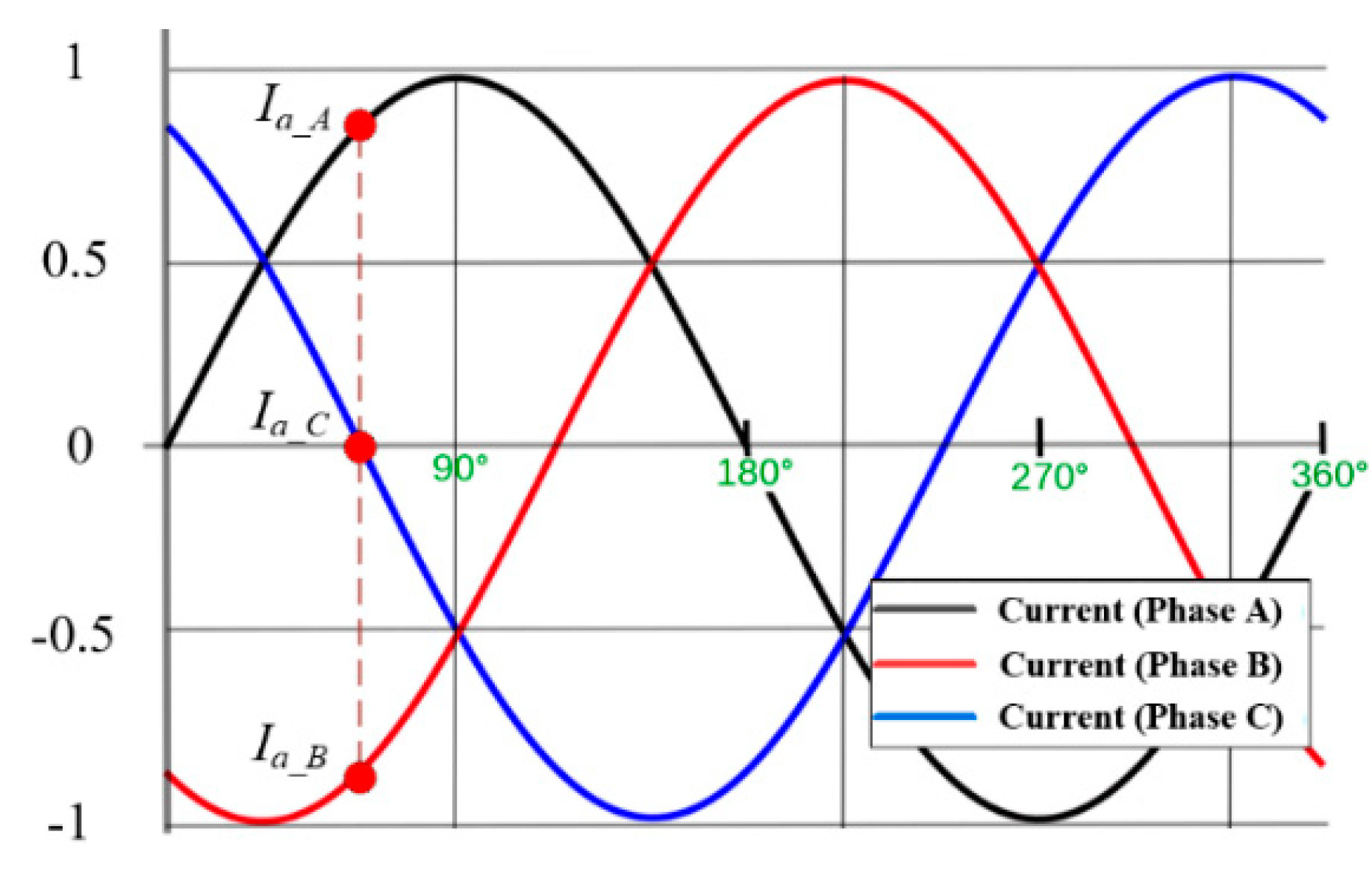
When three-phase armature windings are perfectly aligned and synchronized with DC field windings—i.e., with a power angle of 90°—each phase of the armature windings generates the maximum thrust forces, with the second harmonics of its operating frequency fs on pods with a 120° phase shift, while the sum of the thrust forces results in a total force including its sixth harmonics, as shown in Figure 3a. At the same time, each phase of the armature windings evenly generates guidance forces, and their sum then goes to zero with the same sixth harmonics, as shown in Figure 3b.
Simply, assuming lf = la and wf = wa, the generated maximum forces Fmax on pods can be described as follows:
F max = c μ 0 m a p e N a I a N f I f w f l f τ e α g
where c is the design constant including winding and geometric factors, μ 0 is the permeability of free space, ma is the number of phases, pe is the number of field pole pairs, τ is the pole pitch, α is the gap constant, g is the air-gap, lf and wf are the effective length and width of field windings, Na and Nf are the number of coil turns per phase for armature and DC field windings, and Ia and If are the current of armature and DC field windings, respectively. In Figure 4, la and wa show the effective length and width of armature windings, and gc is the center difference between field and armature windings.
From Equation (1), the thrust force Ft and guidance force Fg can be obtained as follows:
Ft = Fmax sin δ
Fg = − Fmax cos δ
where δ is the power angle. In order to achieve the most efficient operation of the proposed LSMs, the largest Ft and the smallest Fg can be guaranteed when δ is maintained near 90°. For this issue, the real-time location measurement of pods with high-resolutions is a significant technological requirement; therefore, sub-sonic LiDAR sensors are newly adopted for the Hyperloop using the proposed LSMs.
In the case when δ increases from 90°, the thrust forces gradually decrease while repulsive forces significantly increase, as shown in Figure 5. On the other hand, when δ decreases from 90°, thrust forces decrease as attractive forces significantly increase. Therefore, in terms of the dynamic stability of pods, δ should be controlled above 90° to avoid unwanted physical contacts between pods and armatures at a sub-sonic velocity, as these could lead to massive accidents. As shown in Figure 6, each phase of armatures with the DC fields can be simplified as the ideal voltage source, controlled voltage source, controlled current source, inductor and resistance as follows:
V T   =   I a   ( R a   +   j ω s L a )   +   E i
Ra = Np Rpa
La = Np Lpa
Ei = ci pe Na ϕa vs
where VT is the stator voltage for each phase, Ra and La are the total resistance and inductance of armature windings for each phase, respectively, Np is the number of armature poles for each phase, Rpa and Lpa are the resistance and inductance of each pole of armature windings, Ei is the induced voltage generated by moving pods with DC fields on each phase of armature windings, ci is the induced voltage constant, vs. is the speed of pods, and ϕ a is the magnetic flux passing through the armature windings.
At the same time, the mechanical force Fm, which is the same as thrust force Ft, total resistance forces Fr, and effective thrust forces Ff are included in the simplified equivalent circuits and can be summarized as follows:
Fr = Fa + Fd + Fi ≅ Fd
Ff = Fm − Fr = msas
where Fa is the aerodynamic resistance force, Fd is the electrodynamic resistance force, Fi is the incline resistance force, and ms and as are the mass and acceleration of pods. In general, for the LSM design of the Hyperloop, Fr can be simplified as Fm because the Hyperloop is supposed to be operated in flat sub-vacuum tubes resulting in the significant decrease of Fa and Fi. Due to conductive and ferromagnetic materials being used in guideways and tubes as well as electrodynamic levitations, on the other hand, finding the optimal design approach to reducing the electrodynamic resistance force should be one of the main research issues for efficient sub-sonic linear motors.
Next, the electrical power Pe and mechanical power Pm can be simply defined as follows:
Pe = ma Ei Ia cos (γ)
Pm = Fm vs.
Pe = Pm
where γ is the phase difference between the induced voltage and armature phase current.
The electrical parameters of LSMs can be summarized in the phase diagram, as shown in Figure 7, while power equations can be also obtained from the phase diagram as follows:
P = ma VT Ia cos θ
Q = ma VT Ia sin θ
S = ma VT Ia
where P is the active power including electrical DC and AC losses and mechanical propulsion power, Q is the reactive power mainly coming from the inductance of armature windings, and S is the complex power, which is equal to the capacity of LSMs as well as inverters.

3. Proposed Sub-Sonic Linear Synchronous Motor Design Method

3.1. Design Guidelines

For the first step in the design of sub-sonic LSMs, the specifications of the pods should be determined in advance; those have been chosen, as shown in Table 1, considering the size of the sub-vacuum tubes and pods, on-board sub-systems, and driving profile schedules.
As shown in Figure 8, the 3D renderings reflect the final design model of the Hyperloop developed in KRRI and sub-systems such as HTS magnets with four poles–six modules and carbon-fiber monocoque chassis pods of 30,000 kg for 30 passenger seats.
After the design of the pods, in terms of the system engineering of the Hyperloop, HTS magnets represent a significant milestone since all the design parameters of HTS magnets are directly related to the design of armatures and PPSSs, which account for more than half of the total construction cost. Considering the technical limits of HTS magnets, armatures, and PPSSs, therefore, the specifications of HTS magnets have been chosen as shown in Table 2.
Especially, the pole-pitch τ is a significant parameter for the design of inverters because the inverters suffer inevitable increases of their operating frequency f s to double that in Equation (7) when the target sub-sonic velocity for the Hyperloop is twice the maximum speed of Maglev MLX with the same pole-pitch τ of 1.35 m [23]. This problem eventually leads to a doubled increase of the reactive power Q from (6b), which leads to an impractical manufacturing capacity and cost of armatures and inverters.
2 τ f s = v s
f s = v s 2 τ
ω s = 2 π f s
At the same time, the magnetomotive force (MMF) Nf If should be maximized within its technical limitations, as the product of Nf If and Na Ia with given geometries of DC fields and armature windings is a constant for the required thrust forces in Equation (1). Similarly, a single power module of integrated gate-commutated thyristors (IGCTs), which can also provide a high-voltage (~10 kV) rating, guarantees stable operation with an inverter current Ia of 1000 Arms under steady-states, and the current rating is considered to be the right current level for LSMs for the Hyperloop due to the inevitable conduction losses and cost of PPSSs.
L a = N p L p a   N p N a 2 p a
R a = N p R p a     N p ρ N a l a A a
N p = l s τ
However, when Na and Ia are not high enough, this will lead to an unavoidable increase of Na. From Equation (8a), it should be observed that La is directly proportional to the square of Na while Ra is directly proportional to Na. This problem also results in an enormous increase in the active power P, reactive power Q and manufacturing cost of armature windings, which is therefore far from the optimal design of LSMs, as it features poor efficiencies and power factors at sub-sonic speed operation. Here, ls is the length of the armature section for each phase.

3.2. Design of Sub-Sonic Linear Synchronous Motors

For the design of the sub-sonic LSMs, the required thrust forces of the Hyperloop should be calculated, and this can be obtained from the required maximum acceleration of pods and resistance forces. As shown in Figure 9, aerodynamic Fa and electrodynamic Fd resistance forces are obtained by 3D simulation results, and it should be noted that Fa becomes an insignificant factor since pods are operated in a sub-vacuum tube of 0.001 atm.
In addition, as is obtained assuming that EDS levitations using null-flux levitation coils [3] are adopted in the Hyperloop, which has been determined to be the best combination with LSMs using HTS magnets; therefore, Fd can also be variable in accordance with the selection of different levitation methods.
In practice, in order to reach the sub-sonic velocity of 1200 km/h in a short time, the initial target acceleration should be high enough while still being controlled below the limitation of 0.2 G (2 m/s2); otherwise, the acceleration is likely to make passengers feel uncomfortable when it lasts for several minutes. In addition, for the efficient design of LSMPSs, as shown in Figure 10, there are two control regions—i.e., constant force and constant power regions—divided by the reference velocity of 600 km/h.
In the constant force region, inverters flow constant currents into armature windings to generate constant forces on HTS magnets; on the other hand, in the constant power region, the currents and forces gradually decrease as the velocity linearly increases to maintain constant power. In fact, this is one of the most important design approaches to minimize the capacity of LSMs and VVVF inverters considering its practical design; therefore, the control method of the constant power region is essential for our Hyperloop application, even though longer distances are needed to reach its maximum operating speed.
Once the profiles with the two control regions are determined, as shown in Table 3, the design parameters of the proposed sub-sonic LSMs for the Hyperloop can be deducted from the design process addressed in Section 2 and Section 3. In Table 3, it is found that the stator voltages and the minimum capacity of inverters show practical design specifications, which are similar stator voltages of 6 kVrms/phase and half of theinverter capacity of 20 MVA [23] even at a sub-sonic velocity with respect to the JR-Maglev, MLX0.

4. Experimental Verifications

In order to verify the proposed design models of the sub-sonic LSMs, two experimental sets of LSMs with a two pole–one module HTS magnet and two pole–two module electromagnets, respectively, were fabricated for the static and dynamic tests, as shown in Figure 11. Two different test-beds—i.e., static and dynamic propulsion test-beds—should be fabricated in general since it is difficult to verify the characteristics of generated forces between the DC field and armature windings while a pod is moving on guideways.
Due to the limitations of budget and time, the experimental parameters of sub-sonic LSMs in the two test-beds are different from the final design in Table 3; however, it should be noted that it is worthwhile to verify proposed design methods with experimental and simulation results.

4.1. Static Propulsion Tests

In order to conduct the static propulsion test, the reference point at which one of the three-phase currents reaches zero and the others have the same magnitudes of currents, as shown in Figure 12, is selected to validate the characteristics of the generated forces in a time-invariant state.
At the reference point, the experiment sets could therefore be more simplified as inverters can be replaced with DC power supply systems, as shown in Figure 13, which is able to flow Ia of 300 ADC into armature windings; the experimental parameters of the static propulsion test are summarized in Table 4.
As shown in Figure 11a and Figure 13a, seven load-cells (BONGSHIN, DSCK) are adopted in the experimental jig, which is designed for the installation of the two pole–one module HTS magnet, to measure three-axis forces on the HTS magnet while the experimental jig is only able to move to the x-axis (thrust force direction) in order to set the variable δ of one-sided armature windings for the static test. After the experimental jig is located in assigned measurement points of thrust forces, as shown in Figure 13b, the freedom of the minus x-axis is restricted by stoppers to measure thrust forces for safety issues.
The thrust, guidance, and lift forces for different δ values were measured and compared with the simulation results, as shown in Figure 14. As expected from the thrust and guidance force models of Equation (2) and previous simulation results of Figure 5, the thrust and guidance forces are perfectly symmetric with respect to the power angle of 90° and the life forces are zero, as the center to center of the z-axis (lift direction) for both HTS magnets and armature windings are well aligned.
In general, theoretical, simulation and experimental results are well matched to each other except for the measured thrust forces at the power angles of 15° and 165°. This is because the generated thrust forces are smaller than the maximum static friction force of about 200 N for the experimental jig; therefore, the measured thrust forces of the x-axis load-cell indicate zero. In order to solve these issues, maximum static friction forces for each measurement point are measured by the x-axis load-cell and added to the measured thrust forces.

4.2. Dynamic Propulsion Tests

For the dynamic propulsion test, double-sided armature windings are installed on both sides of the guideway in the dynamic test-bed and are modularized with epoxy molding compounds to endure dynamic forces and obtain a lower construction cost and time, as shown in Figure 11b and Figure 15a. In addition, the sub-sonic LiDAR system, which has a measurement resolution of 3 cm and sampling time of 20 ms, is adopted for the synchronization between DC fields and armature windings.
In order to verify the dynamic propulsion test, a small-scaled experimental pod was fabricated and the experimental requirements are summarized in Table 5. Here, the pod includes two pole–one module electromagnets for each side, and third rails and pick-ups are installed on the guideway and pod, respectively, to supply required currents from a DC power supply into moving electromagnets on the pod.
After the requirements are established, as shown in Table 6, main parameters for the dynamic propulsion test can be determined in accordance with the design methods of Section 2 and Section 3. Here, double-sided armature modules are connected in series due to the short test-bed of 20 m, and the air gap g is minimized to maximize the acceleration and velocity of the pod.
Since the sum of measured friction forces from the wheels and pick-ups of the pod is nearly 20 N, the averaged thrust force for 120 N is designed to meet the maximum acceleration of 1 m/s2. As shown in Figure 16, the experimental results from the control data of modular inverters for LSMs show excellent agreement with the requirements and designed parameters in Table 5 and Table 6, which are determined from proposed design methods.

5. Conclusions

In this paper, the characteristics of proposed LSMs with HTS magnets are widely analyzed using the theories as well as simulation results, and optimal design methods for armatures and inverters in terms of the system engineering are newly introduced with the design guidelines and examples for a commercialized version of the Hyperloop. By virtue of the combination of LSMs and electrodynamic suspensions (EDSs) with HTS magnets, a large air-gap of 24 cm, low magnetic resistance forces of below 2 kN, and an efficient as well as practical design of propulsion power supply systems of around 10 MVA could be guaranteed at a sub-sonic velocity. In the experimental verification with two different test-beds—i.e., 6 m long static and 20 m long dynamic propulsion test-beds—it was found that the proposed design models of the sub-sonic LSMs with HTS magnets were well matched with simulation and experimental results under minor numerical errors of 5% in the static and dynamic propulsion tests; therefore, it can be said that proposed design methods and experimental approaches could be guidelines for those aiming to design sub-sonic LSMs for a Hyperloop.

Author Contributions

Conceptualization, S.Y.C. and C.Y.L.; methodology, S.Y.C. and J.Y.L.; software, S.Y.C. and J.Y.L.; validation, J.H.C. and Y.J.O.; formal analysis, J.M.J.; writing—original draft preparation, S.Y.C; writing—review and editing, S.Y.C.; visualization, S.Y.C.; supervision, C.Y.L.; project administration, C.Y.L.; funding acquisition, K.S.L.

Funding

This research was supported by a grant from the R&D program of the Korea Railroad Research Institute, Republic of Korea with the project entitled “Core Technology Development of Subsonic Capsule Train (Hyper Tube Express, HTX).”

Acknowledgments

Su Y. Choi would like to acknowledge the support of the following organizations: Korea National University of Transportation, Changwon National University and SuperGenics in South Korea.

Conflicts of Interest

The authors declare no conflict of interest. The funders had no role in the design of the study; in the collection, analyses, or interpretation of data; in the writing of the manuscript, or in the decision to publish the results.

Nomenclature

FmaxGenerated maximum force.
FtThrust force.
FgGuidance force.
FmMechanical force.
FrTotal resistance force.
FfEffective thrust force.
FaAerodynamic resistance force.
FdElectrodynamic resistance force.
FiIncline resistance force.
cDesign constant including geometric factor.
μoAbsolute permeability of vacuum.
maNumber of phases.
peNumber of field pole pairs.
τPole pitch.
αAir-gap constant.
gAir-gap in x-axis.
gcAir-gap in z-axis.
laEffective length of armature winding.
lfEffective length of field winding.
waEffective width of armature winding.
wfEffective width of field winding.
NaNumber of coil turns for armatures.
NfNumber of coil turns for DC fields.
IaCurrent of armature windings.
IfCurrent of field windings.
δ Power angle.
VTStator voltage for each phase.
RaResistance of armatures for each phase.
LaInductance of armatures for each phase.
NpNumber of armature poles for each phase
RpaResistance of each pole of armatures.
LpaInductance of each pole of armatures.
EiInduced voltage of armatures per phase.
ciInduced voltage constant.
vsSpeed of pods.
msMass of pods.
asAcceleration of pods.
PeElectrical power.
PmMechanical power.
PActive power.
QReactive power.
SComplex power.
γPhase difference between Ei and Ia.
lsLength of the armature section per phase.
fsOperating frequency.
ϕaMagnetic fluxes passing through armature.

References

  1. Abdelrahman, A.S.; Youssef, M.Z. Hyperloop Transportation System: Analysis, Design, Control, and Implementation. IEEE Trans. Ind. Electron. 2018, 65, 7427–7436. [Google Scholar] [CrossRef]
  2. Palacin, R. Hyperloop, the Electrification of Mobility, and the Future of Rail Travel. IEEE Electrif. Mag. 2016, 4, 4–51. [Google Scholar] [CrossRef]
  3. Lee, H.W.; Kim, K.C.; Lee, J. Review of maglev train technologies. IEEE Trans. Magn. 2006, 42, 1917–1925. [Google Scholar]
  4. Lee, H.W.; Park, C.B.; Lee, J. Improvement of thrust force properties of linear synchronous motor for an ultra-high-speed tube train. IEEE Trans. Magn. 2011, 47, 4629–4634. [Google Scholar] [CrossRef]
  5. Bohn, G.; Steinmetz, G. The electromagnetic levitation and guidance technology of the Transrapid test facility Emsland. IEEE Trans. Magn. 1984, 20, 1666–1671. [Google Scholar] [CrossRef]
  6. Yamamura, S. Magnetic levitation technology of tracked vehicles present status and prospects. IEEE Trans. Magn. 1976, 12, 874–878. [Google Scholar] [CrossRef]
  7. Shinha, P. Design of a magnetically levitated vehicle. IEEE Trans. Magn. 1984, 20, 1672–1674. [Google Scholar] [CrossRef]
  8. Rogg, D. General survey of the possible applications and development tendencies of magnetic levitation technology. IEEE Trans. Magn. 1984, 20, 1696–1701. [Google Scholar] [CrossRef]
  9. Fujimoto, T.; Aiba, M.; Suzuki, H.; Umeki, T.; Nakamura, S. Characteristics of electromagnetic force of ground coil for levitation and guidance at the Yamanashi Maglev test line. Q. Rep. Rtri 2000, 41, 63–67. [Google Scholar] [CrossRef]
  10. Space X Website. Available online: https://www.spacex.com/sites/spacex/files/hyperloop_alpha-20130812.pdf (accessed on 25 November 2019).
  11. Mossi, M.; Rossel, P. Swissmetro: A revolution in the high speed passenger transport systems. In Proceedings of the1st Transport Research Conference, Ascona, Switzerland, 1–3 March 2001; pp. 1–16. [Google Scholar]
  12. Lee, H.W.; Cho, S.Y.; Cho, W.Y.; Lee, J.; Kwon, H.B. Analysis of the magnetic effect on the tube infrastructure for a super speed tube train. Int. J. Railw. 2009, 2, 170–174. [Google Scholar]
  13. Korea Railroad Research Institute. Development of Core Technologies of Ultra-High-Speed Tube Train Project; Korea Railroad Research Institute Internal Report; Korea Railroad Research Institute: Gyeonggi-do, Korea, 2009. [Google Scholar]
  14. Virgin Hyperloop One Website. Available online: https://hyperloop-one.com/ (accessed on 25 November 2019).
  15. Hyperloop Transportation Technologies (HTT) Website. Available online: https://www. hyperloop.global/ (accessed on 25 November 2019).
  16. Official YouTube of Virgin Hyperloop One. Available online: http://bitly.kr/BiyXut1 (accessed on 25 November 2019).
  17. Official YouTube of Hyperloop Transportation Technologies (HTT). Available online: https://c11.kr/9y2n (accessed on 25 November 2019).
  18. Ji, W.Y.; Jeong, G.; Park, C.B.; Jo, I.H.; Lee, H.W. A study of non-symmetric double-sided linear induction motor for Hyperloop all-in-one system (propulsion, levitation, and guidance). IEEE Trans. Magn. 2018, 54, 1–4. [Google Scholar] [CrossRef]
  19. Cho, H.W.; Sung, H.K.; Sung, S.Y.; You, D.J.; Jang, S.M. Design and characteristic analysis on the short-stator linear synchronous motor for high-speed maglev propulsion. IEEE Trans. Magn. 2008, 44, 4369–4372. [Google Scholar]
  20. Lee, C.Y.; Lee, J.H.; Lee, J. Conceptual design of superconducting linear synchronous motor for 600-km/h wheel-type railway. IEEE Trans. Appl. Supercond. 2014, 24, 1–4. [Google Scholar] [CrossRef]
  21. Gong, T.; Ma, G.; Qian, H.; Zhang, W. Electromagnetic investigation of a high-temperature superconducting linear synchronous motor for high-speed railway. IEEE Trans. Appl. Supercond. 2018, 28, 1–5. [Google Scholar] [CrossRef]
  22. Park, C.B.; Lee, B.S.; Lee, C.Y. Characteristic analysis of superconducting LSM for the wheel-rail-guided very high speed train according to winding method of the ground 3-phase coils. Trans. Korean Inst. Electr. Eng. 2014, 63, 1164–1169. [Google Scholar] [CrossRef]
  23. Li, J.; Yen, F.; Zheng, S.; Wang, S.; Wang, J. Normal force analysis on a high temperature superconducting linear synchronous motor. IEEE Trans. Appl. Supercond. 2012, 22, 5200304. [Google Scholar]
  24. Zheng, L.; Jin, J.; Guo, Y.; Xu, W.; Zhu, J. Performance analysis of an HTS magnetic suspension and propulsion system with a double-sided HTS linear synchronous motor. IEEE Trans. Magn. 2012, 48, 655–658. [Google Scholar] [CrossRef]
  25. Zheng, S.J.; Yen, F.; Wang, S.Y. Performance of a small –scale high temperature superconducting linear synchronous motor prototype. IEEE Trans. Appl. Supercond. 2012, 22, 5200104. [Google Scholar] [CrossRef]
  26. Gieras, J.F.; Piech, Z.J. Linear Synchronous Motors: Transportation and Automation Systems; CRC Press: Boca Raton, FL, USA, 1999. [Google Scholar]
Figure 1. The overall configuration of sub-sonic linear synchronous motor propulsion systems (LSMPSs) for a Hyperloop adopting long-armature linear synchronous motors (LSMs). HV: high voltage; PWM: pulse width modulation; VVVF: variable-voltage variable-frequency.
Energies 12 04611 g001
Figure 2. The configuration of the proposed Hyperloop with sub-sonic LSMs. (a) Front and bird’s-eye views; (b) simplified one-sided drawing adopting a four pole–one module high-temperature superconducting (HTS) magnet and air-core electromagnets in the left-side.
Energies 12 04611 g002
Figure 3. The 3D simulation results (Infolytica MagNet) of normalized thrust and guidance forces when the armature windings are perfectly synchronized with DC field windings at a sub-sonic velocity: (a) thrust forces; (b) guidance forces.
Energies 12 04611 g003
Figure 4. Definition of the dimensions of the proposed LSMs: (a) HTS magnets (two poles); (b) three-phase armature windings with a pitch lp of 2 τ /3; (c) HTS magnet on the armature winding.
Energies 12 04611 g004aEnergies 12 04611 g004b
Figure 5. The 3D simulation results of averaged total thrust and guidance forces along with variable power angles in the case when g >   τ, 3; here, lift forces are zero with a gc of 0: (a) normalized thrust forces; (b) normalized guidance forces.
Energies 12 04611 g005
Figure 6. (a) Simplified equivalent circuit of LSMs and (b) simulation result of induced voltages for each phase under the no-load condition.
Energies 12 04611 g006
Figure 7. The phase diagrams of LSMs for each phase.
Energies 12 04611 g007
Figure 8. Three-dimensional rendering of the pod of the Hyperloop: (a) outside; (b) inside.
Energies 12 04611 g008
Figure 9. Simulation results of resistance forces for our Hyperloop model along with velocity: (a) aerodynamic resistance force; (b) electrodynamic resistance force with a gc of 5 cm.
Energies 12 04611 g009
Figure 10. Profiles of forces, currents, and accelerations with proposed sub-sonic LSMs along with the velocity of pods.
Energies 12 04611 g010
Figure 11. Two experimental sets of the sub-sonic LSMs: (a) 6 m long static propulsion test-bed; (b) 20 m long dynamic propulsion test bed; (c) fabricated HTS magnet for the static test.
Energies 12 04611 g011
Figure 12. Diagram of three-phase currents—i.e., the current of phase A Ia_A, B Ia_B, and C Ia_C—showing the reference point at which one of three-phase currents reaches zero and the others have the same magnitudes of currents.
Energies 12 04611 g012
Figure 13. Experimental sets of the LSMs for the static propulsion test: (a) test-bed with the HTS magnet installed on the experimental jig; (b) one of the four mechanical stoppers on linear guide rails.
Energies 12 04611 g013
Figure 14. Experimental and 3D simulation (Infolytica, MagNet) results of generated forces along with variable power angles with gc of 0 for the static propulsion test: (a) air-gap of 14 cm, (b) 17 cm, (c) and 20 cm.
Energies 12 04611 g014aEnergies 12 04611 g014b
Figure 15. Experimental sets of the LSMs for the dynamic propulsion test: (a) dynamic test-bed with a pod with two pole–two module electromagnets; (b) sub-sonic LiDAR system for the precision non-contact location measurement of a pod; (c) modular inverters for LSMs.
Energies 12 04611 g015
Figure 16. Experimental results of the dynamic propulsion test with a small-scaled pod.
Energies 12 04611 g016
Table 1. Given requirements of sub-sonic pods and sub-vacuum tubes.
ParameterValueUnit
Total Mass of Pod, ms30,000kg
Max. Acceleration, as2m/s2
Length (Diameter) of Pod35 (2)m
Diameter of Sub-Vacuum Tubes3.2m
Passenger Seats30-
Table 2. Given requirements of HTS magnets adopting a four pole–six module system.
ParameterValueUnit
Magnetomotive Force of HTS Magnets, Nf If750kA·Turns
Number of Total Poles of HTS Magnets, Pe24-
Operating Temperatures30K
Air Gap, g0.24m
Pole Pitch, τ2.7M
Effective Length, lf (Width, wf)2 (0.6)m
Table 3. Design parameters of one-sided sub-sonic LSMs with HTS magnets adopting a four pole–six modules setup.
ParameterValueUnit
DC FieldsMagnetomotive Force, Nf If750kADC·Turns
Number of Total Poles, Pe12one-sided
Pole Pitch, τ 2.7m
Air Gap, g0.24M
Effective (Length lf/Width wf )(2.25, 0.6)m
ArmaturesPhase Currents (600/1200 km/h), Ia(1000/500)Arms
Number of Coil Turns per Phase, Na2Turns
Magnetomotive Force (600/1200 km/h), Na Ia(2.8/1.4)kApeak·Turns
Induced Voltages (600/1200 km/h], Ei(2.7/5.4)kVrms/Phase
Total Resistance per Section, Ra0.59Ω/Phase
Total Inductance per Section, La8.99mH/Phase
Effective (Length la/Width wa )(1.6/0.72)m
Cross Sectional Area of Litz-wire Conductors300mm2/turn
InvertersStator Voltages (600/1200 km/h), VT(3.7/6.0)kV/phase
Frequency (600/1200 km/h), fs(31/62)Hz
Section Length2km
Inverter Capacity (600/1200 km/h)(11/9)MVA
Table 4. Experimental parameters of the static propulsion test of one-sided LSMs with HTS magnets adopting a two pole–one module setup.
ParameterValueUnit
DC FieldsMagnetomotive Force, Nf If150kADC·Turns
Operating Current, Iop84ADC
Total Number of Coil, Nf1784Turns
Number of Total Poles, pe2one-sided
Operating Temperature<40K
Cooling MethodConductive Colling-
Tape Material (SuNAM Co.)GdBCO-
Pole Pitch, τ 0.81m
Air Gap, g0.17m
Effective (Length lf/Width wf )(0.6, 0.3)m
Inductance5.2H
ArmaturesPhase Currents, Ia300ADC
Number of Coil Turns per Phase, Na11Turns
Magnetomotive Force, Na Ia3300ADC·Turns
Effective (Length la/Width wa )(0.46/0.32)m
Cross Sectional Area of Al Conductors80mm2/turn
Table 5. Given requirements of the dynamic propulsion test with a small-scaled pod.
ParameterValueUnit
Total Mass of Pod, ms100kg
Max. Acceleration, as1m/s2
Max. Velocity, vs3(10)m (km/h)
Length of Pod1.5m
Length of Test-bed20m
Table 6. Designed parameters of the dynamic propulsion test of double-sided LSMs with electromagnets adopting a two pole–two module setup.
ParameterValueUnit
DC FieldsMagnetomotive Force, Nf If6kADC·Turns
Number of Total Poles, pe4one-sided
Pole Pitch, τ 0.81m
Air Gap, g0.07m
Effective (Length lf/Width wf)(0.6, 0.3)m
ArmaturesPhase Currents, Ia300ADC
Number of Coil Turns per Phase, Na11Turns
Magnetomotive Force, Na Ia3300ADC·Turns
Induced Voltages [10 km/h], Ei1Vrms/Phase
Total Resistance per Section, Ra0.35Ω/Phase
Total Inductance per Section, La6.35mH/Phase
Effective (Length la/Width wa)(0.46/0.32)M
Cross Sectional Area of Al Conductors80mm2/turn
InvertersStator Voltages (10 km/h), VT37Vrms/phase
Frequency (10 km/h), fs1.85Hz
Section Length40m
Required Inverter Capacity15kVA

