Article

Distributed Dynamic Economic Dispatch of an Isolated AC/DC Hybrid Microgrid Based on a Finite-Step Consensus Algorithm

College of Energy and Electrical Engineering, Hohai University, Nanjing 211100, China
*
Author to whom correspondence should be addressed.
Energies 2019, 12(24), 4637; https://doi.org/10.3390/en12244637
Submission received: 6 November 2019 / Revised: 2 December 2019 / Accepted: 4 December 2019 / Published: 6 December 2019
(This article belongs to the Section F: Electrical Engineering)

Abstract

:
The AC/DC hybrid microgrid is the main trend of microgrids’ development, and the dynamic economic dispatch is regarded as an important way to ensure the economic and safe operation of a microgrid system. In this paper, a dynamic economic dispatch model of the isolated AC/DC hybrid microgrid is developed with the objective of minimizing the daily operation cost of controllable units. Furthermore, a distributed algorithm based on the finite-step consensus algorithm is proposed, in which the incremental cost of each distributed generation unit is set as a consensus variable, and all units obtain the optimal values by exchanging information only with their neighbors. In addition, the algorithm converges to the optimal solutions in finite steps, and the efficiency is improved significantly. The effectiveness of the proposed model and the algorithm were verified by simulation.

Graphical Abstract

1. Introduction

With increasing concern of the shortage of fossil fuels and environment pollution, the renewable energy sources, such as wind and solar, are being developed quickly to improve the sustainability of the energy supply. As an integration of distributed generations and load systems, microgrids (MGs) have attracted wide attention [1,2,3,4] in recent years, in order to efficiently integrate DC distributed power sources, such as photovoltaic and fuel cell energy storage devices; and DC loads, such as electric vehicles, LED lighting, etc. Consequently, the need for AC/DC hybrid microgrids (HMGs) has been emerged. AC/DC hybrid microgrids (HMGs) have been proposed [5,6,7]. Since those HMGs consist of AC and DC buses, both AC and DC loads could be connected directly, which greatly decreases the number of the AC/DC converters, and the loss caused by multi-stage power conversion can also be reduced.
The economic dispatch (ED) and coordinated control of a MG is essential for its economic and reliable operation. Recently, the centralized control model was adopted [8,9,10,11,12]. In the microgrid control center (MGCC), each power generation, energy storage and load unit in the microgrid were unified and coordinated. In spite of their simple structure and high control precision, their flexibility and reliability were poor. When MGCC network faced an attack or communication structure change, the centralized control mode could not achieve control objectives. In this condition, the distributed control was proposed [13,14,15,16], where the global communication and unified control were not necessary. Using the distributed control, the global optimization can be achieved by its own information and its neighboring units’ information. Distributed control could also satisfy the requirements of plug-and-play of distributed power generation, and ensure the privacy of users’ information in microgrids.
A consensus algorithm is an important method for distributed control. So far, many studies on consensus algorithms to solve the economic dispatch problem in microgrids have been carried out in [17,18,19,20,21]. In [22], based on leader-follower, a two-tier consensus algorithm was proposed to solve ED problem with the objective of minimizing generation cost, but it still needed leaders to collect global information. In [23], a fully distributed consensus algorithm was presented with a cost increment as a consensus variable. In [24], considering the communication between generation unit and load unit, and taking the incremental cost of a generation unit and the incremental benefit of a flexible load as consensus variables, a consensus algorithm based on the feedback of supply-demand mismatch was proposed to solve the energy management problem of a microgrid. In [25], a novel, distributed approach for the economic dispatch problem was proposed; a flooding-based consensus approach was applied. A consensus algorithm was utilized in [26] to estimate local information in a distributed way; the saddle point method was also combined with it to dynamically seek the optimal solution to the ED problem, and the algorithm’s stability was analyzed by Lyapunov stability theory. In [27], an improved power flow control strategy of the BMC based on VSM for the hybrid AC/DC microgrid was proposed. For the other relevant results, please refer to [28,29].
However, it should be noted that the consensus algorithms used in the aforementioned research were all asymptotic, where their convergence characteristics depended on the communication topology and did not have a convergence requirement. The practical application often requires that the system have a fast response speed, short convergence time, and be able to achieve consensus in a limited time. In [30,31], the distributed finite-step consensus algorithms (FSCA) were used to solve the coordination control problem of microgrid. Applying the FSCA, better convergence performance in solving the ED problem of microgrid was obtained in [31]. Additionally, most of the microgrids adopted in the previous works were either AC nor DC; there are few research efforts which were carried for the hybrid AC/DC microgrids. In addition, currently, the consensus algorithm is mainly used for single-period ED; multi-period, dynamic ED considering the coupling constraints in different periods, such as generator climbing, state of charge (SOC) of battery energy storage system (BESS), and so on, should be further investigated.
Based on the grid structure of AC/DC-HMG, the mathematical models of each controllable unit are established in this paper. Considering the generation cost of conventional units, the operation cost of energy storage units, and the wind and photovoltaic units’ abandonment cost, and aiming at optimizing the comprehensive economic cost, the distributed FSCA was adopted to solve the multi-period dynamic ED problem of AC/DC-HMG.
The main contributions of this paper are summarized as follows:
  • A distributed, finite-step consensus algorithm has been proposed for dynamic economic dispatch problem of AC/DC-HMG, which is seldom investigated. Based on our algorithm, the optimal output power of generations in both the AC side and DC side could be obtained in a distributed way.
  • Different from other distributed algorithms, our proposed algorithm can be converged to the optimal value in finite steps, which is associated with the communication topology. Therefore, the computation time is effectively reduced.
  • Our algorithm is more suitable for AC/DC-HMG containing various distributed generations. The algorithm can efficiently address the features of plug and play, and it can be suitable for communication link failures.

2. Optimal Dispatching Model of AC/DC Hybrid Microgrid

2.1. AC/DC-HMG Structure

The structure of the isolated AC/DC-HMG studied in this paper is shown in Figure 1. From Figure 1, it can be seen that the power conversion units play important roles in the hybrid AC/DC-HMG, which connects the AC and DC sub-microgrids. The wind turbines (WT) are connected to AC buses, while photovoltaic (PV) units are connected to DC buses. Both AC and DC microgrids contain traditional generators (TG), battery storage units (BS), and AC/DC load units (Load). AC and DC buses are connected by AC/DC bi-directional converters. M1 is power monitoring point of AC/DC tie-line. The dotted lines represent the communication links between the units.

2.2. Dynamic ED Model for AC/DC-HMG

Our study is based on the isolated AC/DC hybrid microgrid. The dynamic economic dispatch problem of AC/DC-HMG is solved by our proposed distributed algorithm. It is assumed that AC/DC-HMG contains conventional, wind, and photovoltaic units; battery storage units; and load units, and all the units are connected with local agents, which can communicate with neighbors. Based on the information exchange under our proposed distributed consensus algorithm, the dynamic economic dispatch problem can be solved efficiently in a distributed way. The dynamic ED model is established as follows:

2.2.1. Objective Function

The total operation cost includes the cost of TGs, BSs, WTs and PVs. Hence, the objective function is written as
min t = 1 T [ i S T G C i ( P T G , i ( t ) ) + j S W T C j ( P W T , j ( t ) ) + k S S L C k ( P S L , k ( t ) ) + r S B S C r ( P B S , r ( t ) ) ] ,
where T is the number of time periods in the daily dispatching cycle. Each period is taken as one hour; i.e., 24 periods a day. S T G is the set of TG units, S W T is the set of WT units, S S L represents the set of PV units, and S B S is the set of BS units. P T G , i ( t ) , P W T , j ( t ) , P S L , k ( t ) , and P B S , r ( t ) are the active output powers of the ith TG, jth WT, kth PV, and rth BS over a time period t , respectively. C i ( P T G , i ( t ) ) , C j ( P W T , j ( t ) ) , C k ( P S L , k ( t ) ) , and C r ( P B S , r ( t ) ) are the generation cost functions of the corresponding unit set. The cost function of each controllable unit is modelled as a form of convex function, particularly, the quadratic function form, which is adopted by most existing literature [22,23,24].
Operation cost function of TGs: The operation cost function of the ith TG can be modelled as a quadratic function
C i ( P T G , i ( t ) ) = a i ( P T G , i ( t ) ) 2 + b i P T G , i ( t ) + c i , i S T G ,
where a i , b i , and c i are the cost function coefficients.
Operation cost function of WT and PV units: The cost functions of WT and PV power curtailment units’ abandoned power can be expressed as
C j ( P W T , j ( t ) ) = ω j [ P W T , j ( t ) P W T , j s t ( t ) ] 2 , j S W T
C k ( P S L , k ( t ) ) = ω k [ P S L , k ( t ) P S L , k s t ( t ) ] 2 , k S S L ,
where ω j and ω k are the cost coefficients of WT and PV units’ abandoned powers, P W T , j s t ( t ) is the maximum adjustable power of jth WT over a time period t , and P S L , k s t ( t ) denotes the maximum adjustable power of PV unit k over a time period t .
Operation cost function of BS units: The operation cost function of the BS unit can be expressed by
C r ( P B S , r ( t ) ) = a r ( P B S , r ( t ) ) 2 , r S B S ,
where a r is the cost function coefficient.

2.2.2. Constraints

Active power supply-demand balance constraints: The AC/DC-HMG should meet the following real-time supply and demand balance constraints
i S T G P T G , i ( t ) + j S W T P W T , j ( t ) + k S S L P S L , k ( t ) + r S B S P B S , r ( t ) = s S D M P D M , s ( t ) ,
where S D M is the set of all load units in the AC/DC-HMG, and P D M , s ( t ) represents the load demand value of load unit s over a time period t .
In addition, active power balance constraints should also be satisfied in the microgrid’s DC and AC regions. The DC side constraint is written as
k S S L P S L , k ( t ) + r S B S P B S , r ( t ) + P A C D C ( t ) = s S D C D M P D C D M , s ( t ) ,
where P A C D C ( t ) is the interaction power of AC and DC converter tie-line. The active power is transferred from AC side to DC side if it is positive, and vice versa. S D C D M denotes the set of DC load units, and P D C D M , s ( t ) is the value of DC load unit s over a time period t .
The AC side constraint is as follows:
i S T G P T G , i ( t ) + j S W T P W T , j ( t ) P A C D C ( t ) = s S A C D M P A C D M , s ( t ) ,
where S A C D M is the set of AC load units, and P A C D M , s ( t ) denotes the value of AC load unit s over a time period t .
Operation constraints of TG units: The active power output of ith TG must be kept between the upper and lower limits as
P T G , i min ( t ) P T G , i ( t ) P T G , i max ( t ) ,
where P T G , i min ( t ) and P T G , i max ( t ) are the active power lower and upper limits, respectively.
The output climbing constraint is formulated as
Δ P T G , i d P T G , i ( t ) P T G , i ( t 1 ) Δ P T G , i u ,
where Δ P T G , i u and Δ P T G , i d are the maximum active powers of the ith TG that can be increased or decreased over a time period [ t 1 , t ] .
Operation constraints of BS units: The output power of the rth BS should be maintained within the upper and lower limits of charging and discharging powers
P ¯ B S , r P B S , r ( t ) P ¯ B S , r ,
where P B S , r ( t ) is the output power of the BS unit, which is positive at discharge and negative at charge. P ¯ B S , r and P ¯ B S , r are the upper and lower limits of the charge and discharge powers of the BS unit.
The SOC constraint on charged state of BS unit is written as
S O C B S , r min S O C B S , r ( t ) S O C B S , r max ,
where S O C B S , r max and S O C B S , r min are the upper and lower limits of the charge and discharge powers.
The capacity continuity constraints of BS units can be modelled as
S O C B S , r ( t ) = { S O C B S , r ( t 1 ) P B S , r ( t ) η r c h Δ T E r P B S , r ( t ) < 0 S O C B S , r ( t 1 ) P B S , r ( t ) Δ T E r η r d i s    P B S , r ( t ) 0 ,
where η r c h and η r d i s are the charging and discharging efficiencies; E r is the maximum capacity of BS unit, and Δ T is the time step.
Considering the power and capacity constraints of the BS unit, the upper and lower active power adjustable limits can be obtained as
{ P B S , r max ( t ) = min ( P ¯ B S , r , P B S , r c h ( t ) ) P B S , r min ( t ) = max ( P ¯ B S , r , P B S , r d i s ( t ) ) ,
where P B S , r c h ( t ) and P B S , r d i s ( t ) are the powers required for charging the BS unit to the upper limit and discharging it to the lower limit. P B S , r max ( t ) and P B S , r min ( t ) represent the upper and lower limits of the adjustable active power output.
The WT and PV output powers are constrained as
0 P W T , j ( t ) P W T , j s t ( t )
0 P S L , k ( t ) P S L , k s t ( t ) .
The AC/DC tie-line constraint is given by
P A C _ D C min P A C _ D C ( t ) P A C _ D C max ,
where P A C _ D C max and P A C _ D C min are the limits of the transmission power on the tie-line. P A C _ D C min is negative, representing the lower limit of power transferred from DC to AC sub-microgrids.

2.2.3. Karush–Kuhn–Tucker (KKT) Optimal Conditions

The Lagrange multiplier method is applied to deal with single-period distributed ED model, where λ represents Lagrange multiplier. Without considering inequality constraints, the original optimization problem is transformed into
min L = i S T G C i ( P T G , i ) + j S W T C j ( P W T , j ) + k S S L C k ( P S L , k ) + r S B S C r ( P B S , r ) + λ ( s S D M P D M , s i S T G P T G , i j S W T P W T , j k S S L P S L , k r S B S P B S , r )
St .   { L P T G , i = C i ( P T G , i ) P T G , i λ = 2 a i P T G , i + b i λ = 0 L P W T , j = C j ( P W T , j ) P W T , j λ = 2 ω j ( P W T , j P W T , j s t ) λ = 0 L P S L , k = C k ( P S L , k ) P S L , k λ = 2 ω k ( P S L , k P S L , k s t ) λ = 0 L P B S , r = C r ( P B S , r ) P B S , r λ = 2 a r P B S , r λ = 0 .
When the incremental cost of each unit is equal, the Lagrange function L reaches the minimum value. Then, the optimal incremental rate λ is obtained. The corresponding operation cost coefficients are integrated to have a unified form
2 a ˜ i P i + b ˜ i λ = 0 , i S T G S W T S S L S B S
P i = λ b ˜ i 2 a ˜ i ,
where a ˜ i and b ˜ i are the operation cost factors of the integrated unit i , while P i represents the active power.

3. Finite-Step Consensus Dynamic Economic Dispatch Strategy

3.1. The Overview of Graph Theory

Un-directed connected graph G = ( V , E ) is used to describe the communication topology graph of AC/DC-HMG. V = { 1 , 2 , , n } is the set of vertices in the graph, while E V × V denotes the set of edges. A = { a i j } n × n is the adjacent matrix of undirected graph, where the diagonal element a i i = 0 . If vertices i and j have communication connection, then a i j = a j i = 1 ; otherwise, a i j = a j i = 0 . Neighbouring nodes of node i can be represented as N i = { j V | ( j , i ) E } ; d i = j N i a i j denotes the degree of node i .
The degree matrix of graph G is defined as diagonal matrix D = d i a g { d i } ; then, the Laplacian matrix L = D A of graph G is obtained. The diagonal element of matrix L is defined as l i i = i j a i j ; the non-diagonal element is defined as l i j = a i j . For undirected graph G , its Laplacian matrix s is a symmetric positive semidefinite matrix. Graph G is a connected graph if and only if L has a zero eigenvalue and all other eigenvalues are positive.

3.2. Finite-Step Consensus Algorithm

In an undirected network topology, in order to achieve consensus, each node needs to update its own state and its adjacent nodes’ states, which can be expressed as
x i k + 1 = r i i x i k + j N i r i j x j k
where x i k denotes the state of node i at iteration k . r i i is the update coefficient of the node’s own state. r i j is the state update coefficient of adjacent nodes. Rewriting Equation (22) into the matrix form, we have
X k + 1 = R k X k ,
where R k = ( r i j ) is a symmetrical matrix.
If R k is a doubly stochastic matrix, the asymptotic convergence of state values can be achieved. In order to achieve finite-step convergence, matrix R k needs to be revised.
Lemma 1:
Assuming that the Laplacian matrix of an undirected connected topological graph has D + 1 different eigenvalues δ 1 δ 2 δ D + 1 , the following auxiliary matrices are constructed by using those eigenvalues
R k = ( α k + N max β ) I β L ( k = 1 , , D , β 0 )
{ β = 1 i = 2 D + 1 δ i D α k = δ k + 1 N max i = 2 D + 1 δ i D , k = 1 , 2 D ,
where N max = max { N 1 , , N n } .
Then, selecting the operation cost incremental rate as a consensus variable, Equation (22) can achieve average consensus in finite steps. According to the principle of equal incremental rate, the ED problem of AC/DC-HMG is solved in a distributed manner, and the algorithm converges in a finite step.
Without considering unit operation constraints: Assuming that there are n units in an AC/DC-HMG, including TGs, WTs, PVs, and BS units, and considering that each unit has its own local load, the total load power can be expressed as
P D M = i = 1 n P D M , i , i S T G S W T S S L S B S ,
where P D M represents the total load power.
According to the criterion of equal increment rate and (20), the expression of optimal incremental cost can be obtained as
λ * = i = 1 n ( P D M , i + b ˜ i 2 a ˜ i ) i = 1 n 1 2 a ˜ i .
The FSCA is used to solve the optimal increment rate. The initial values V i 0 and W i 0 in a single time period are set as
{ V i 0 = P D M , i + b ˜ i 2 a ˜ i W i 0 = 1 2 a ˜ i .
According to the communication topology of AC/DC-HMG, the corresponding auxiliary matrix R k = ( r i j ) ,   ( k = 1 , 2 , , D ) is constructed by Equations (24) and (25) and updated iteratively as
{ V i k + 1 = r i i V i k + j N i r i j V j k W i k + 1 = r i i W i k + j N i r i j W j k .
Hence,
{ λ i k = V i k W i k P i k = λ i k b ˜ i 2 a ˜ i .
Then, after D steps of iteration, the increment rate and power of the unit can reach the optimal values; namely, λ i k D λ * and P i k D P i * .
Considering unit operation constraints: When the steady-state power of each unit is obtained using the above algorithm, it may not satisfy its operation constraints; then, those units need to be processed further. If Ω represents a set of units beyond the constraints, i.e.,. Ω = { i { 1 , 2 , , n } | P i P i max P i P i min } , then Equation (20) can be represented as
λ ¯ * = 2 a ˜ i P ¯ i + b ˜ i , i Ω .
For unit i that does not exceed the power limit, its power value can be expressed as
P ¯ i = λ ¯ * b ˜ i 2 a ˜ i , i Ω .
For units that exceed the power limit, the limit is used as the steady-state power value.
P ¯ i = { P i max , P ¯ i > P i max P i min , P ¯ i > P i min , i Ω .
According to the power balance of AC/DC-HMG, the following equation is derived
P D M = i Ω P ¯ i + i Ω P ¯ i .
Substituting Equation (32) into (34), we get
P D M = i Ω P ¯ i + i Ω λ ¯ * b ˜ i 2 a ˜ i .
Therefore, considering the unit power constraints, the optimal incremental cost of each unit can be expressed as
λ ¯ * = ( P D M i Ω P ¯ i ) + i Ω b ˜ i 2 a ˜ i i Ω 1 2 a ˜ i .
The FSCA is also used to solve the optimal increment rate. The initial values Q i 0 , Y i 0 , and Z i 0 are set as
Q i 0 = { P D M , i P ¯ i , i Ω P D M , i , i Ω
Y i 0 = { b ˜ i 2 a ˜ i , i Ω 0 , i Ω
Z i 0 = { 1 2 a ˜ i , i Ω 0 , i Ω .
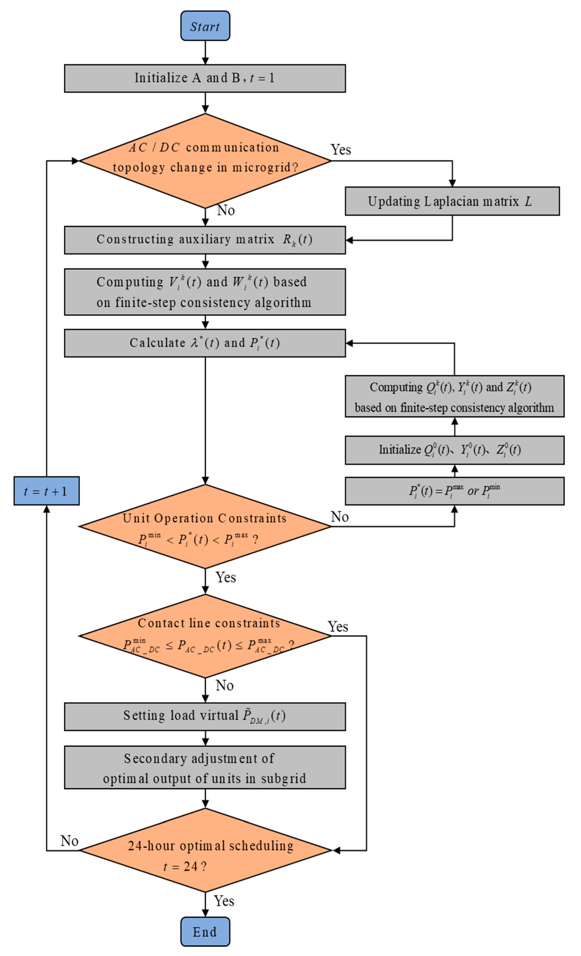
According to the communication topology of the AC/DC-HMG, the auxiliary matrix R k = ( r i j ) ,   ( k = 1 , 2 , , D ) is constructed and updated according to the following criteria
{ Q i k + 1 = r i i Q i k + j N i r i j Q j k Y i k + 1 = r i i Y i k + j N i r i j Y j k Z i k + 1 = r i i Z i k + j N i r i j Z j k .
Then, it can be calculated by
P ¯ i k = { λ ¯ k b ˜ i 2 a ˜ i i Ω P i min   or   P i max i Ω .
Then, after Dth iterations, the increment rate and power of the unit can reach the optimal value; namely, λ i k D λ * and P i k D P i * .

3.3. Secondary Adjustment Strategy Based on Virtual Load Value

In the optimal dispatch based on distributed FSCA, the transmission power on the tie-line is monitored continuously. When the tie-line operation constraints are not satisfied and the transmission power is beyond the limit, a secondary adjustment strategy based on virtual load value is carried out to handle this issue. In this case, the optimal dispatches of AC and DC sub-microgrids will be achieved, respectively.
Tie-line power adjustment: At time t , the transmission power of the tie-line exceeds the limit if P A C D C ( t ) > P A C D C max ; then, P A C D C ( t ) = P A C D C max , whereas, if P A C D C ( t ) < P A C D C min , then P A C D C ( t ) = P A C D C min .
Updating load virtual values: The measured value of local load’s active power demand in each sub-microgrid is updated to the load’s virtual value. The case of s is taken as an example.
In AC sub-microgrid,
P ˜ D M , i ( t ) = P D M , i ( t ) + P A C D C max p .
Among them, P ˜ D M , i ( t ) is the load’s virtual value carried by the local unit after secondary adjustment, and p is the number of units in the AC sub-microgrid.
In DC sub-microgrid
P ˜ D M , i ( t ) = P D M , i ( t ) P A C D C max q ,
where q is the number of units in the DC sub-microgrid.
Secondary coordination optimal scheduling: AC and DC sub-microgrids adjust units’ outputs based on the FSCA. Each unit in the sub-microgrids interacts with other units in its internal communication network, and achieves the optimal dispatch of each sub-microgrids, while meeting the interconnection constraints of AC/DC-HMG. The flow chart of the proposed finite-step consensus dynamic ED strategy is depicted in Figure 2.
Remark 1:
A distributed finite-step consensus algorithm is proposed for dynamic economic dispatch problem. The convergence time is faster than other algorithms which have asymptotic convergence. Because of this, the communication time is less, so our proposed algorithm effectively relieves the calculation burden. Only in finite steps, can the optimal output power of generations be obtained, and the supply-demand balance can also be satisfied. Therefore, our proposed algorithm can be applied to a real application.

4. Case Study

Taking the isolated AC/DC-HMG as a case study, a typical microgrid structure shown in Figure 1 was selected to study the characteristics of a microgrid with high penetration of intermittent energy sources. Dynamic ED was carried out based on FSCA. All the case studies were completed based on MATLAB 2013a software, and the computer configuration was 8G RAM, 2.60 GHz. With renewable energies as the main resources, the microgrid’s minimum daily generation cost was formulated to promote its renewable penetration. The low-voltage AC/DC-HMG is considered in this paper, assuming that the communication network of the microgrid has a simple connection structure, which can be equivalent to a simple load or source network. The equivalent topology of the microgrid network is given in Figure 3, where it consists of eight controllable units; namely, four traditional motor units, two BS devices, two WT units, and two PV units. Each unit is represented by an agent, and the incremental cost of each cell is chosen as a consensus variable. Based on the FSCA, neighbouring units interact with each other and update local information. Within eight iteration steps, the incremental cost of all units reach their optimal values, and the global optimization result is obtained.
The scheduling time of the AC/DC-HMG studied in this paper is 24 h; one period of dispatch is 1 h; and the load demand is constant in a single period. Based on the optimal output of the last period, the microgrid can be re-optimized to ensure the safe and stable operation of the microgrid in the whole scheduling time. The typical daily load, PV output, and WT output data are given in Table 1.
In isolated operation mode, only the capacity constraints of the bidirectional converter connected to the AC side and the DC side need to be considered—60 kW in this case. The upper and lower limits of the BS device’s capacity were E s max and E s min , respectively. The charging efficiency η s 1 and discharging efficiency η s 2 were both 0.9. The generation cost coefficients and operation parameters of distributed generation units are listed in Table 2.
The distributed dynamic ED strategy of the AC/DC-HMG based on FSCA was tested. Under the above initial conditions, the model was built in MATLAB platform and continuous simulations were carried out for 24 periods. The simulation results of the 24 h period are illustrated in Figure 4. The total computation time was 665.016 ms. Even though in a large system, the computation time will satisfy the requirements of real-time applications, it can be seen that in 24 periods of one day, the system can always satisfy the supply-demand balance even under the load fluctuation and uncertainties of renewable energy output based on our proposed distributed ED strategy.

4.1. The Global Optimal Plan of Single-Period Analysis

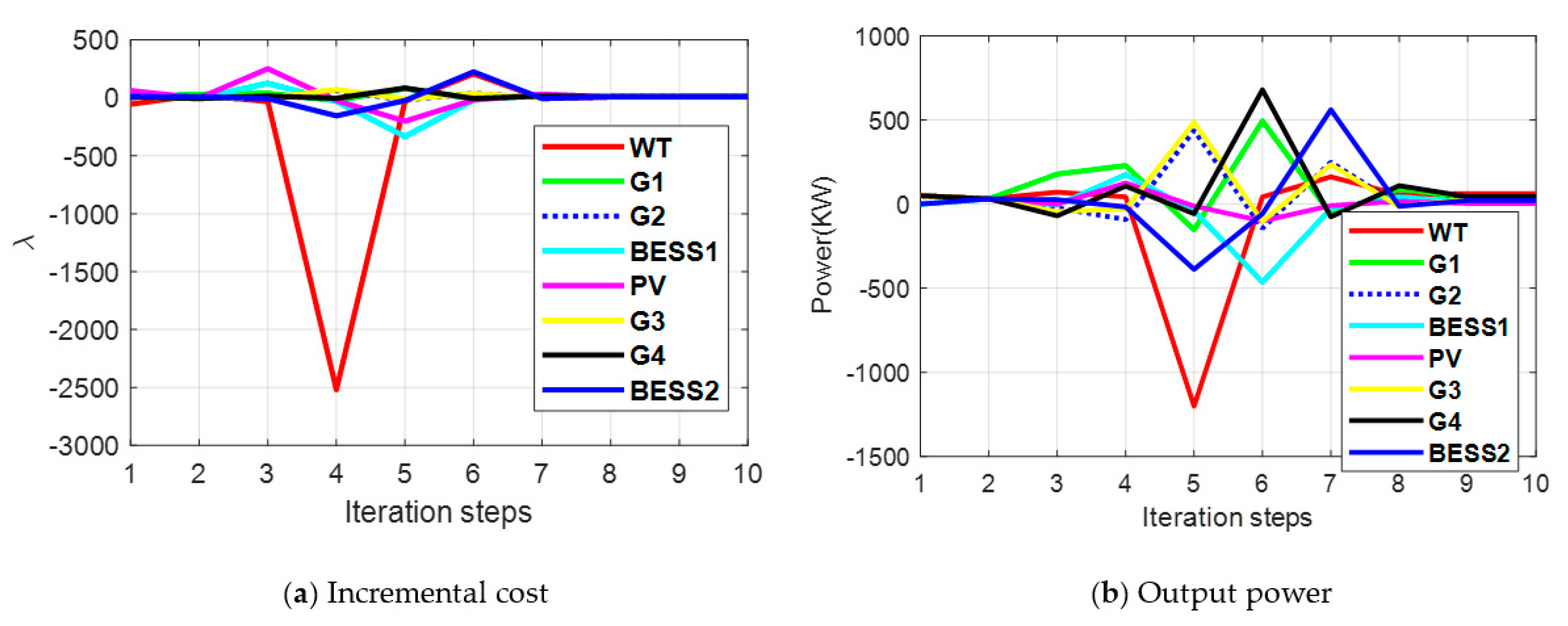
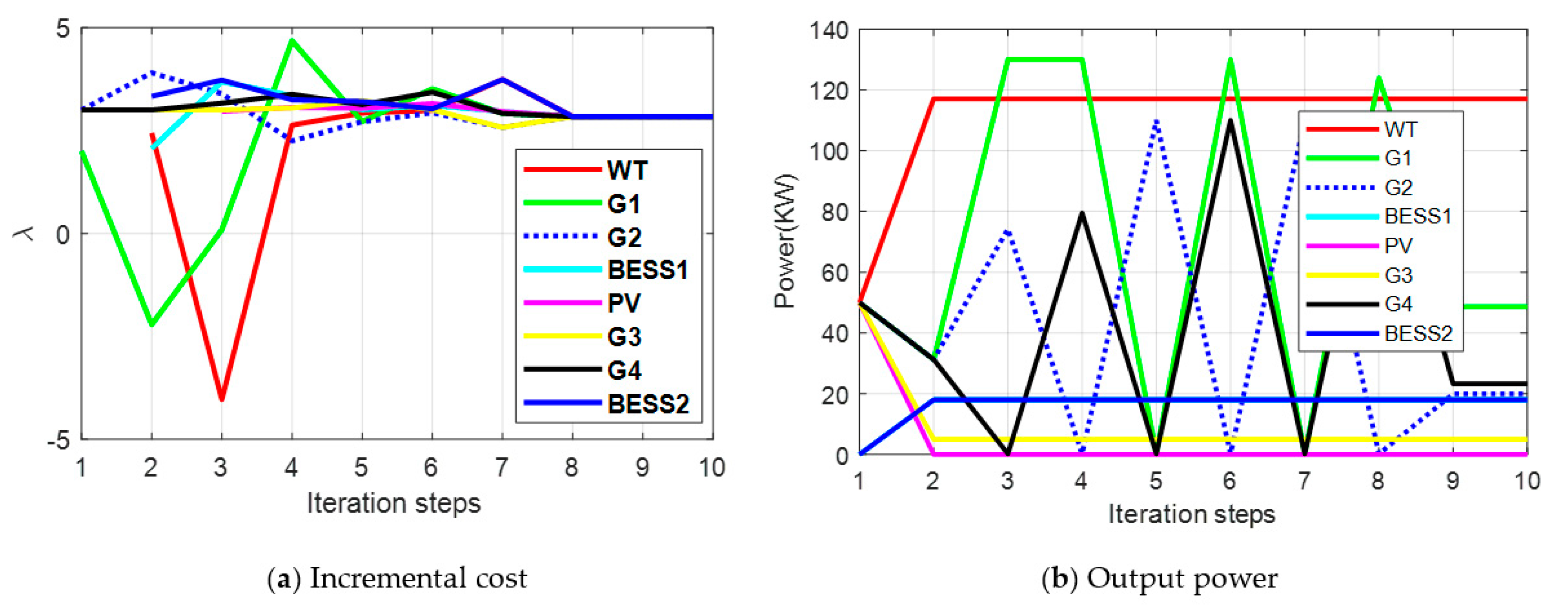
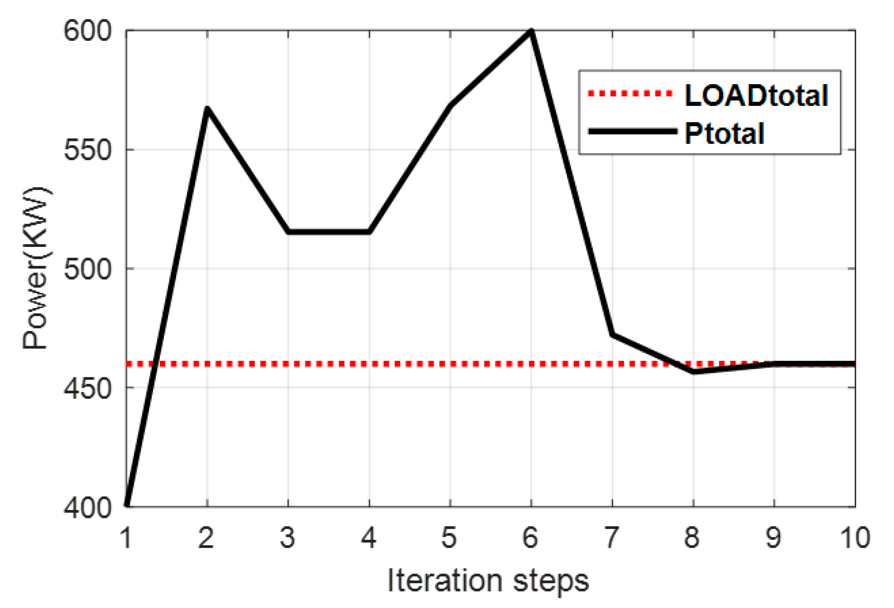
The realization of the global optimal plan is guaranteed by the fact that the interactive power between AC and DC sides does not exceed the tie-line power constraint. The active power dispatch of the microgrid under the global optimal plan was analysed by taking the time period from 00:00 to 01:00 as an example. Figure 5 depicts the convergence of the incremental rate without considering the output constraints. Obviously, the incremental rate converges within eight steps, where the optimal incremental rate is 8.2629. Figure 6 shows that with the convergence of the incremental cost, the active power optimization results of each output unit are 62.6915, 39.1433, 37.5924, 11.4763, 4.1314, 30.4495, 43.8578, and 20.6573 kW, respectively. However, the TG output exceeds the output constraint, the PV output exceeds the climbing constraint, and the BS output exceeds the capacity constraint. In this case, although the optimization results meet the system supply-demand balance, the system is unstable.
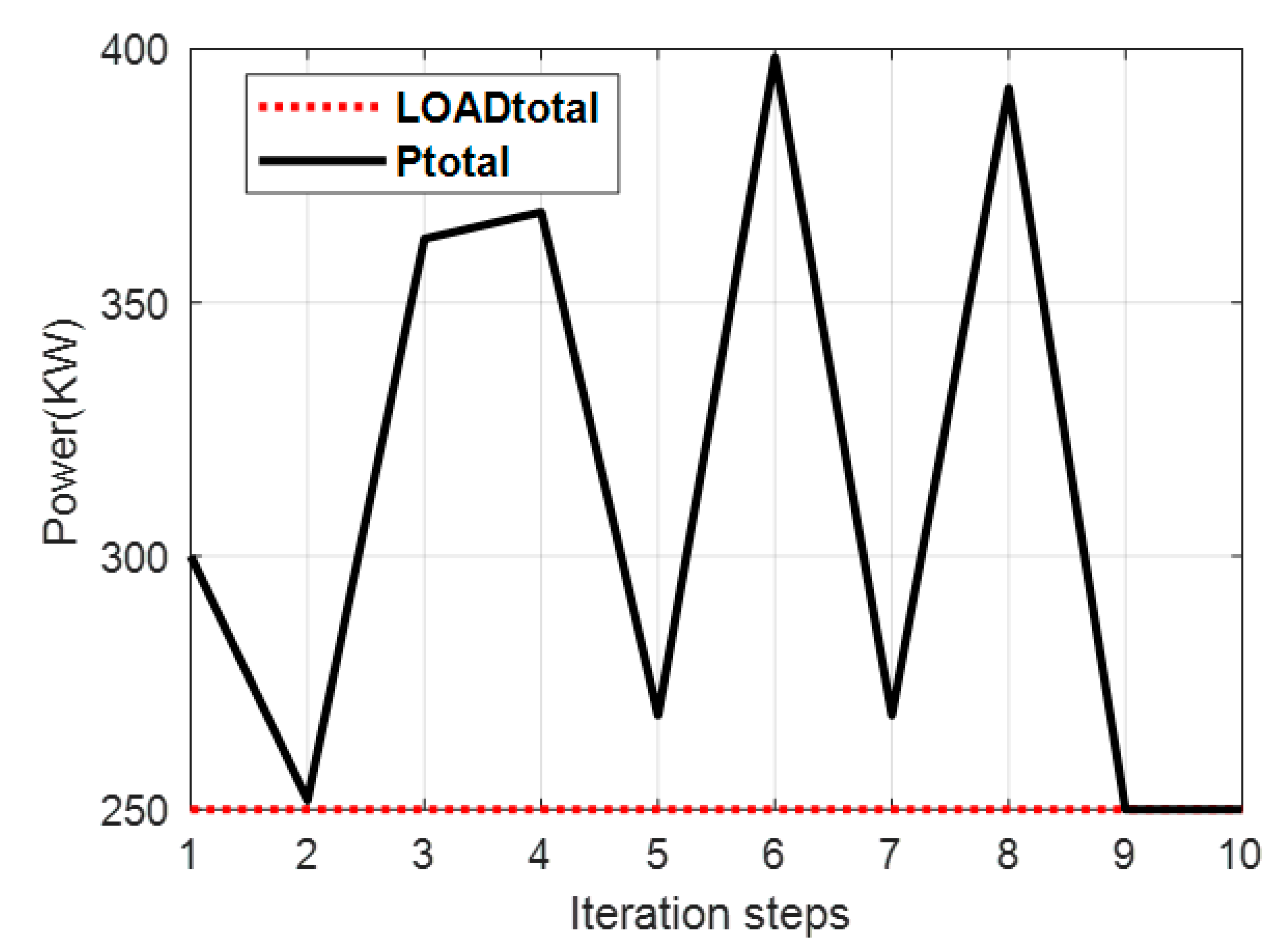
By selecting constraints-violating units, operating them at the output constraint point at a constant time, the units’ outputs that do not exceed the constraints are re-optimized. The new optimization results are demonstrated in Figure 6 and Figure 7. At this time, the optimal active output of each unit was adjusted to 117.1202, 48.6914, 19.9330, 18, 0, 5, 23.2552, and 18 kW, respectively. The optimization results satisfy both the output constraints and the supply-demand balance constraint. The tie-line power between AC and DC sides was 27.9895 kW, which did not exceed the capacity constraints of bidirectional converters, proving that the global optimal plan is feasible.

4.2. The Sub-Microgrid Independent Optimal Plan of Single-Period Analysis

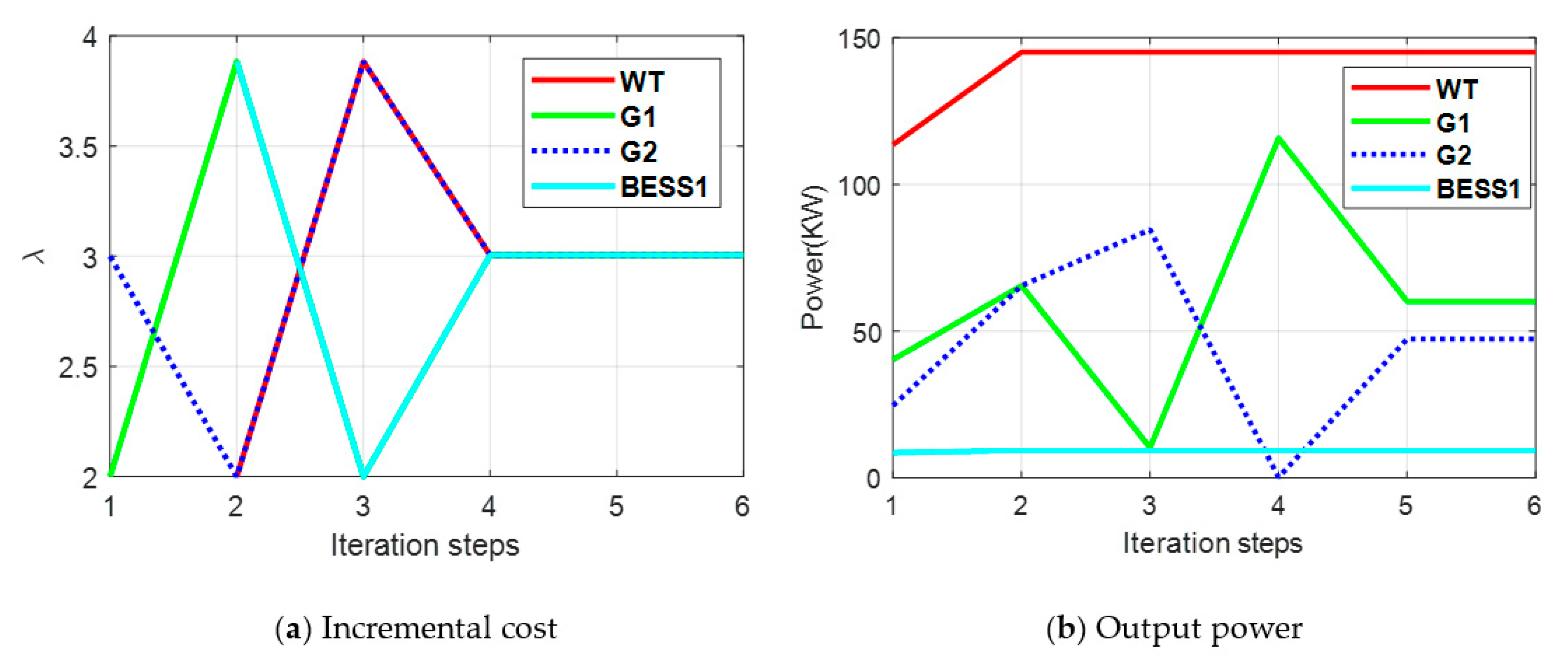
The sub-microgrid optimal plan is a supplement to the global optimal plan. Aiming at solving the problem of excessive interaction power between AC and DC sides, the sacrificial unit is proposed to achieve the global optimal output to minimize the generation cost of the sub-microgrid. The AC and DC sub-microgrids were optimized separately. The sub-microgrid independent optimal situation was analyzed by taking the time period 12:00–13:00 as an example. Under the global optimal plan, as illustrated in Figure 8 and Figure 9, the micro-incremental rate of all units converges to 3.0833 in the eighth step. The optimal output of each unit was 145.0894, 32.1477, 15.3117, 9.4269, 170, 53.1919, 17.8636 and 16.9684 kW, respectively. The overall power supply and demand of the system were balanced. The interaction power between AC and DC sides was 76.8713 kW, which exceeds the constraints. Therefore, the optimal dispatch strategies of AC and DC sub-microgrids were adopted, respectively.
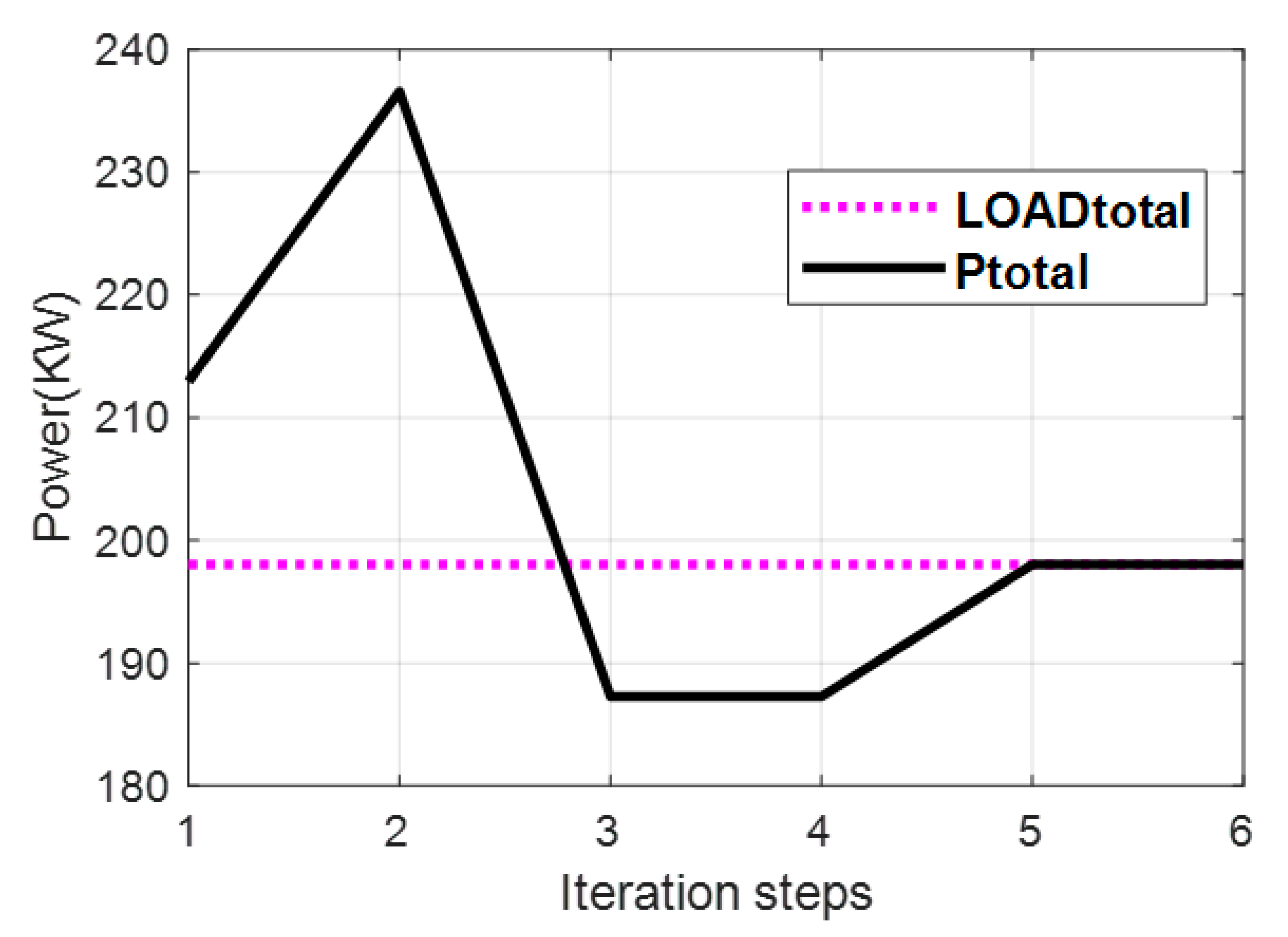
By updating the virtual load values of AC and DC sub-microgrids, the load was readjusted. The principle of load distribution is based on the balance of supply and demand of the whole network. After completing the virtual value adjustment, the active power of distributed generation units in the AC and DC sub-microgrids are independently optimized. As shown in Figure 10, Figure 11, Figure 12 and Figure 13, the optimal incremental cost of AC sub-microgrid was 3.0044. The optimal active power output of each unit in AC sub-microgrid was 79.8527, 78.8507, 82.9722, and 20.3001 kW, respectively. The optimal incremental cost of DC microgrid was 2.9163, and the optimal active power output of each unit in DC sub-microgrid was 89.5083, 35.8340, 50.1397, and 22.5419 kW, respectively. Moreover, it satisfies the constraints of operation and the supply-demand balance in the region, so the sub-microgrid independent optimization plan is feasible.

5. Conclusions

Aiming at overcoming the disadvantages of poor robustness of centralized communication and long iteration steps of distributed communication in AC/DC hybrid microgrids, a fully distributed dynamic ED model based on FSCA was proposed. The management model is divided into two layers. The upper layer optimizes the system output based on the interactive information of the distributed generation units, whereas the lower layer calculates the potential of the power according to the optimal output of the upper layer units, adjusted the virtual value of the load, ensuring the supply-demand balance of the sub-networks, and satisfying the capacity security constraints of the bidirectional converter. The effectiveness of the dynamic ED plan was verified by the simulation analysis of two sets of examples. In the management method, the FSCA achieved the optimal economic operation of the system. In the control mechanism, the load virtual value adjustment strategy ensured the supply-demand balance and stable operation constraints of the system. Based on our proposed FSCA, the ED problem for AC/DC-HMG was solved in a fully distributed manner. Besides that, the proposed algorithm is more robust and flexible for addressing the plug-and-play features, greatly alleviating computation and communication burden.
The proposed management strategy could be further applied to a multi-microgrid system with more complex structure, an AC/DC hybrid distribution network, or energy internet. However, this method does not carry out in-depth discussions on communication time delay, information packet loss, communication link failure, and so on. Therefore, the optimization of communication links, the effect of communication time delay, and the adaptation of convergence coefficient could be the future research direction of this work.

Author Contributions

K.J. developed the concept, conceived the experiments, designed the study, and wrote the original manuscript. X.Z. performed the experiments and evaluated the data. F.W., L.S., and K.L. reviewed and edited the manuscript. All authors read and approved the manuscript.

Funding

This work was supported in part by National Science Foundation of China under grant 51422701, in part by the Innovation Team of Six Talent Peaks Project of Jiangsu Province under grant 2019-TD-XNY -001, and in part by China ‘111’ project of “Renewable Energy and Smart Grid”: B14022.

Conflicts of Interest

The authors declare no conflict of interest.

References

  1. Hooshyar, A.; Iravani, R. Microgird protection. Proc. IEEE 2017, 105, 1332–1353. [Google Scholar] [CrossRef]
  2. Liu, X.; Wang, P.; Loh, P. A hybrid AC/DC microgrid and its coordination control. IEEE Trans. Smart Grid 2014, 2, 278–286. [Google Scholar]
  3. Akinyele, D.; Belikov, J.; Levron, Y. Challenges of microgrids in remote communities: A steep model application. Energies 2018, 11, 432. [Google Scholar] [CrossRef] [Green Version]
  4. Mohamed, S.; Shaaban, M.F.; Ismail, M.; Serpedin, E.; Qaraqe, K.A. An efficient planning algorithm for hybrid remote microgrids. IEEE Trans. Sustain. Energy 2019, 10, 257–267. [Google Scholar] [CrossRef]
  5. Aprilia, E.; Meng, K.; Al Hosani, M.; Zeineldin, H.H.; Dong, Z.Y. Unified power flow algorithm for standalone AC/DC hybrid microgrids. IEEE Trans. Smart Grid 2019, 10, 639–649. [Google Scholar] [CrossRef]
  6. Papari, B.; Edrington, C.; Bhattacharya, I.; Radman, G. Effective energy management of hybrid AC–DC microgrids with storage devices. IEEE Trans. Smart Grid 2019, 10, 193–203. [Google Scholar] [CrossRef]
  7. Li, Z.; Shahidehpour, M. Small-signal modeling and stability analysis of hybrid AC/DC microgrids. IEEE Trans. Smart Grid 2019, 10, 2080–2095. [Google Scholar] [CrossRef]
  8. Duan, J.; Yi, Z.; Shi, D.; Lin, C.; Lu, X.; Wang, Z. Reinforcement-learning-based optimal control of hybrid energy storage systems in hybrid AC–DC microgrids. IEEE Trans. Ind. Inform. 2019, 15, 5355–5364. [Google Scholar] [CrossRef]
  9. Gao, H.; Liu, J.; Wang, L.; Wei, Z. Decentralized energy management for networked microgrids in future distribution systems. IEEE Trans. Power Syst. 2018, 33, 3599–3610. [Google Scholar] [CrossRef]
  10. Xu, S.; Yan, Z.; Feng, D.; Zhao, X. Decentralized charging control strategy of the electric vehicle aggregator based on augmented Lagrangian method. Int. J. Electr. Power Energy Syst. 2019, 104, 673–679. [Google Scholar] [CrossRef]
  11. Damousis, I.; Bakirtzis, A.G.; Dokopoulos, P.S. Network-constrained economic dispatch using real-coded genetic algorithm. IEEE Trans. Power Syst. 2003, 18, 198–205. [Google Scholar] [CrossRef]
  12. Gaing, Z. Particle swarm optimization to solving the economic dispatch considering the generator constraints. IEEE Trans. Power Syst. 2003, 18, 1187–1195. [Google Scholar] [CrossRef]
  13. Long, H.; Fan, X.; Liu, S. Review of distributed consensus problem in multi-agent system. Comput. Eng. Appl. 2013, 49, 36–42. [Google Scholar]
  14. Ahmad, J.; Tahir, M.; Mazumder, S. Dynamic economic dispatch and transient control of distributed generators in a microgrid. IEEE Syst. J. 2019, 13, 802–812. [Google Scholar] [CrossRef]
  15. Chen, G.; Li, C.; Dong, Z. Parallel and distributed computation for dynamical economic dispatch. IEEE Trans. Smart Grid 2016, 8, 1026–1027. [Google Scholar] [CrossRef]
  16. Han, Y.; Zhang, K.; Li, H. MAS-based distributed coordinated control and optimization in microgrid and microgrid clusters: A comprehensive overview. IEEE Trans. Power Electron. 2018, 33, 6488–6508. [Google Scholar] [CrossRef] [Green Version]
  17. Wang, R.; Li, Q.; Zhang, B.; Wang, L. Distributed consensus based algorithm for economic dispatch in a microgrid. IEEE Trans. Smart Grid 2019, 10, 3630–3640. [Google Scholar] [CrossRef]
  18. Zhang, W.; He, X. Stealthy attack detection and solution strategy for consensus-based distributed economic dispatch problem. Int. J. Electr. Power Energy Syst. 2018, 103, 233–246. [Google Scholar] [CrossRef]
  19. Ross, M.; Abbey, C.; Bouffard, F.; Joos, G. Microgrid economic dispatch with energy storage systems. IEEE Trans. Smart Grid 2018, 9, 3039–3047. [Google Scholar] [CrossRef]
  20. Yun, H.; Shim, H.; Ahn, H. Initialization-free privacy-guaranteed distributed algorithm for economic dispatch problem. Automatica 2019, 102, 86–93. [Google Scholar] [CrossRef] [Green Version]
  21. Hamdi, M.; Chaoui, M.; Idoumghar, L.; Kachouri, A. Coordinated consensus for smart grid economic environmental power dispatch with dynamic communication network. IET Gener. Transm. Distrib. 2018, 12, 2603–2613. [Google Scholar] [CrossRef]
  22. Zhang, Z.; Chow, M. Convergence analysis of the incremental cost consensus algorithm under different communication network topologies in a smart grid. IEEE Trans. Power Syst. 2013, 27, 1761–1768. [Google Scholar] [CrossRef]
  23. Yang, S.; Tan, S.; Xu, J. Consensus based approach for economic dispatch problem in a smart grid. IEEE Trans. Power Syst. 2013, 28, 4416–4426. [Google Scholar] [CrossRef]
  24. Xu, Y.; Li, Z. Distributed optimal resource management based on the consensus algorithm in a microgrid. IEEE Trans. Ind. Electron. 2015, 62, 2584–2592. [Google Scholar] [CrossRef]
  25. Li, B.; Zhang, P.; Li, J.; Cao, X. Distributed absorption and half-search approach for economic dispatch problem in smart grids. Energies 2019, 12, 1527. [Google Scholar] [CrossRef] [Green Version]
  26. Bai, L.; Sun, C.; Ye, M.; Hu, G. Distributed economic dispatch control via saddle point dynamics and consensus algorithms. IEEE Trans. Control Syst. Technol. 2017, 27, 898–905. [Google Scholar] [CrossRef]
  27. Liu, Z.; Miao, S.; Fan, Z.; Liu, J.; Tu, Q. Improved power flow control strategy of the hybrid AC/DC microgrid based on VSM. IET Gener. Transm. Distrib. 2019, 12, 81–91. [Google Scholar] [CrossRef]
  28. Zhai, X.; Wang, N. Multi-agent consensus algorithm-based optimal power dispatch for islanded multi-microgrids. Energies 2019, 7, 679. [Google Scholar]
  29. Le, L.; Zhou, Q.; Zhao, L.; Wang, Y. Research on the real-time distributed economic dispatch strategy for microgrids. Energies 2019, 12, 4007. [Google Scholar] [CrossRef] [Green Version]
  30. Li, Y.; Dong, P.; Liu, M.; Yang, G. A distributed coordination control based on finite-time consensus algorithm for a cluster of DC microgrids. IEEE Trans. Power Syst. 2019, 34, 2205–2215. [Google Scholar] [CrossRef]
  31. Chen, G.; Zhao, Z.; Li, Z. Distributed finite-step iterative algorithm for economic dispatch of generation. IEEE Trans. Ind. Inform. 2018, 14, 5221–5232. [Google Scholar] [CrossRef]
Figure 1. The structural chart of a AC/DC hybrid microgrid.
Energies 12 04637 g001
Figure 2. The flow chart of finite-step consensus dynamic economic dispatch (ED) algorithm.
Energies 12 04637 g002
Figure 3. Microgrid network topology.
Energies 12 04637 g003
Figure 4. Dynamic optimal scheduling of the microgrid.
Energies 12 04637 g004
Figure 5. Simulation results without output constraints.
Energies 12 04637 g005
Figure 6. Simulation results considering output constraints.
Energies 12 04637 g006
Figure 7. Supply-demand balance considering output constraints.
Energies 12 04637 g007
Figure 8. Simulation results before secondary adjustment.
Energies 12 04637 g008
Figure 9. Supply-demand balance before secondary adjustment.
Energies 12 04637 g009
Figure 10. Simulation results in AC sub-microgrid after secondary adjustment.
Energies 12 04637 g010
Figure 11. Supply-demand balance AC sub-microgrid after secondary adjustment.
Energies 12 04637 g011
Figure 12. Simulation results in DC sub-microgrid after secondary adjustment.
Energies 12 04637 g012
Figure 13. Supply-demand balance DC sub-microgrid after secondary adjustment.
Energies 12 04637 g013
Table 1. Daily load, photovoltaic (PV) and wind turbine (WT) output.
Time EriodLoad/kWPV/kWWT/kW
00:00—01:002500117.120218535654
01:00—02:002200121.521251478584
02:00—03:001900114.206082843385
03:00—04:00150091.9048293624883
04:00—05:00160089.0762082204174
05:00—06:001500131.614010287532
06:00—07:001901581.7427863655850
07:00—08:0025035131.453977290065
08:00—09:0035095128.907351493896
09:00—10:00400130135.226389034385
10:00—11:00350150100.563661757176
11:00—12:00400180113.566138886138
12:00—13:00460170145.089441537814
13:00—14:0041015094.3964155018810
14:00—15:0031012056.0018819779476
15:00—16:0029095136.674989699932
16:00—17:0030070113.118873426901
17:00—18:003605085.5073651878849
18:00—19:0064010149.700327160665
19:00—20:00720072.4171498983127
20:00—21:007200115.245107296861
21:00—22:006000110.499064190826
22:00—23:00500088.7245431483135
23:00—24:00360064.2187159290504
Table 2. Operation parameters of microgrid system.
No.UnitaibiPi,u (kW/h)Pi,d (kW/h)[Pmin,Pmax] (kW)
1WT1.00[0, —]
2G10.0828075[0.3, 300]
3G20.0736055[0.2, 200]
4BESS10.360 [−30, 30]
5PV1.00[0, —]
6G30.0745045[0.1, 100]
7G40.0636055[0.2, 200]
8BESS20.200 [−60, 60]