Article

An Intelligent Bio-Inspired Cooperative Decoupling Control Strategy for the Marine Boiler-Turbine System with a Novel Energy Dynamic Model

College of Automation, Harbin Engineering University, Harbin 150001, China
*
Author to whom correspondence should be addressed.
Energies 2019, 12(24), 4659; https://doi.org/10.3390/en12244659
Submission received: 25 November 2019 / Revised: 30 November 2019 / Accepted: 2 December 2019 / Published: 8 December 2019
(This article belongs to the Section F: Electrical Engineering)

Abstract

:
This paper presents an intelligent bio-inspired cooperative decoupling control strategy (IBICDC) for the problems of modeling difficulties and strong coupling in the marine boiler-turbine system (MBTS). First, the model of the main steam pressure control loop is successfully constructed by introducing the Martin-Hou equation, which solves the modeling difficulty caused by the complexity of structure, operation mechanism, and operation conditions, as well as the characteristics of nonlinearity, parameter time-varying, and time-delay in the marine boiler (MB). According to the mathematic method of homeomorphic mapping relationship between the rotational speed and the kinetic energy in the marine steam turbine with propeller (MSTP) and the feedback linearization method, the nonlinear degree of the MSTP rotational speed control loop model is reduced and the infinite point of discontinuity in the rotational acceleration when the rotational speed close to 0 is eliminated. Then, the IBICDC inspired by the internal environment regulation mechanism of human body is applied to the strong coupling problem between the two control loops, namely, to eliminate the large value sudden change of the main steam pressure caused by the change of operation conditions. The conventional decoupling methods are also presented. Finally, detailed numerical simulations are conducted to validate the effectiveness of the IBICDC strategy.

Graphical Abstract

1. Introduction

The 21st century is a century for human beings to explore the ocean. With the depletion of land resources, people pay an increasing attention to the ocean, with the ship technology playing an increasingly important role in social development. As the source of ship power, the related technology of marine power plant needs to be developed. As a large proportion of marine power plants, many technical problems of marine boiler-turbine system (MBTS) have not been effectively solved. One of the problems that attracts the attention of the academic and engineering circles is the problem of strong coupling between MB and MSTP. This problem has been around for a long time, the main difficulties are as follows:
1. Difficulty in modeling: The structure and operation mechanisms as well as the strong nonlinear and time-delay characteristics of MBTS are extremely complex. Moreover, there are few relevant authoritative literatures, and most of the authoritative literatures are about the modeling of steam power plant in the thermal power station in land [1,2,3,4,5,6,7,8,9,10,11,12,13].
2. Variable operation conditions: Because of the variable ship sailing speed and frequent switching of operate conditions in MBTS, it is difficult for traditional modeling methods to describe the dynamic characteristics of MBTS in the full range of operating conditions accurately.
Because steam is not an ideal gas, the relationship between steam pressure and density and temperature is a complex binary equation, which makes it difficult to model the main steam pressure in the mechanism method.
In addition, the MB structure is complex, and the process from fuel combustion to the main steam generation is a complex heat transfer process, so it is difficult to establish the analytical relationship between steam flow and fuel. In reference [1,2,13], in order to simplify the problem, some simple empirical formulas are used to describe the analytical relationship between the main steam pressure and the fuel. However, because of the variable operating conditions of the MBTS, the empirical formulas are difficult to accurately calculate the main steam pressure under all operating conditions. In reference [11,12], a model of the main steam pressure control loop is built based on the operation data of MBTS by using the method of system identification, but the output characteristics of the MBTS under all working conditions cannot be accurately calculated. The work of reference [2,3,4,5,10] has brought a good idea to the modeling of steam pressure in this paper. The conventional modeling method of MSTP rotational speed control loop is using the Newton’s second law to construct the mechanical equation between the rotational acceleration and the resultant torque. The disadvantages of the conventional methods are nonlinear, complex structure and infinite point of discontinuity in the rotational acceleration when the rotational speed is close to 0.
At the same time, according to [14], the international requirements for ship energy conservation and emission reduction are higher, which makes people have higher performance requirements for MBTS, resulting in unsatisfactory control performance of conventional decoupling control algorithms. The coupling brings challenges to the acquisition of excellent control performance [4]. The reason why conventional control algorithms cannot provide satisfactory control performance [5,6] lies not only in the coupling and time-delay, but also in the high complexity, nonlinearity, and parameter variation in the MBTS [7].
For MBTS, it is important to eliminate the coupling influences between the two control loops to guarantee the system operates normally [15]. Decoupling control is to solve coupling problems [16]. There are many decoupling methods, such as open-loop precompensation decoupling methods [17,18], matrix decoupling methods [19] (including identification matrix algorithm and diagonal matrix algorithm), feed-forward compensation decoupling methods [20], and pole-placement decoupling methods [21]. In the early 1990s, various advanced decoupling control strategies have been proposed, e.g., intelligent decoupling control technologies [22,23,24,25,26,27,28] (including fuzzy decoupling algorithm, neural-networks decoupling algorithm, support vector machine decoupling algorithm, genetic decoupling algorithm, self-adaptive decoupling algorithm, and kernel decoupling algorithm), the robust decoupling technologies [1], and coordinate control technologies [1,4,8,9]. The decoupling control methods above have the following disadvantages [1]: (1) high complexity, those theories are of high complexity in the structure to be well understood; (2) difficulty in accurate mathematical models, high dependency of accurate mathematical models which can be a heavy burden to the computing capacity [10,11,28]; and (3) poor control performance, for which decoupling effectiveness is no satisfactory [10,12]. Hence, the decoupling algorithms above are more or less impracticable when implemented in MBTS. With the sudden rise in bio-inspired control schemes, the decoupling control strategies with bio-inspired algorithm have been already proposed [29]. As is well-known to us, the internal environments in human body are of high complexities, and are highly stable with strongly coupling and harmonious regulation. The extraordinary performances attract many researchers to study the regulation principles of the internal environments of the human body [15,29,30,31]. Inspired by the physiological modulation system in the human body, some researchers have already proposed some decoupling methods, which have achieved satisfactory results [29,31,32]. Compared with the conventional decoupling control algorithms, IBICDC is more easily and practically applied in the industrial control field and can acquire a better control performance.
The rest of the paper is organized as follows: Section 2.1 briefly introduces the MBTS and the modeling methods used in the paper; Section 2.2 presents the mathematical analysis and design of IBICDC. In Section 3, the simulation settings and results are summarized, and the effectiveness of the proposed method is verified. Then, in Section 4, conclusions and future work are summarized.

2. Materials and Methods

2.1. Modeling of MBTS

MBTS is an uncertain, time-varying, and non-linear multi-input and multi-output (MIMO) system [1]. The whole system is highly complex [2] and it can be divided into MB and MSTP parts. MB is responsible for the production of superheated and saturated steam (also called the main steam), the structure of which is shown in Figure 1. MB has ten parts. Furnace is the combustion unit, which burns fossil fuels (heavy petroleum) and releases a lot of heat [3]. The heat converts water in the drum into steam. The mixture of water and steam circulates between the steam drum and the mud drum through the Raiser and Downcomer. The steam in the superheater becomes superheated and saturated which is then used to drive the MSTP. In the MSTP, the main steam expands to work and drive the MSTP rotating or changing its rotational speed. The two components of MBTS are connected closely, and the devices of the two components exhibit different mechanical and control characteristics. The working conditions of MBTS are of high complexity, which need to be switched from one working condition to another frequently. Hence the dynamic characteristics of two components are not synchronous. So, when MBTS switches from one working condition to another, it can make the main steam pressure unstable, which in turn leads to a fluctuation in the rotational speed of the MSTP. This phenomenon is called coupling problem [1].

2.1.1. Combustion and Heat Exchanging

In the furnace of MB, heat emits from the fuel combustion [10,11]. The heat exchanging process mainly include two ways [3]: a certain amount of heat of combustion exchanges in components such as Downcomer, Mud Drum, and Riser in the radiation manners, the left heat is exchanged through high temperature gas in the Superheater. At last, the main steam is generated in the Superheater. The combustion and heat exchanging processes can be expressed by the Equation (4):
m ( s ) u 1 ( s ) = K 1 ( T 1 s + 1 ) ( T 2 s + 1 ) e τ 1 s
where m denotes the main steam mass flow; u1 is the fuel mass flow; K1 is the gain of the processes; τ1 is the time delay of the process; T1 and T2 are the time constant of combustion and heat exchanging, respectively.

2.1.2. The Main Steam Pressure

The pressure of the main steam is a critical variable, and a main steam pressure with a good performance makes a boiler much more excellent than others [10,15]. Steam pressure is a function of temperature and density and the analytic formula of pressure state is very complex [33]. More than hundreds of gas state equations have been proposed [33], but most of them have no practical value and poor accuracy when applied in the practice.
Reference [33] presents a state equation of steam pressure, temperature, and volume as follows:
P ( T , V ) = R T V b + j = 2 A j + B j T + C j T e 5.475 T C T ( V b ) j
where, R is the universal gas constant, 8.314472J/(K·mol); T denotes temperature, K; V is the molar volume of gases, m3/mol; P(V,T) denotes the steam pressure, Pa; b is the specific constant of steam volume, Pa(m3/mol)j; Aj, Bj, and Cj are the characteristic constants.
Equation (2) is of high complexity and needs a large computation when applied in the practice. Hence, in this research, a much further simplified analytic formula is delivered [10].
P ( T , V ) = R T V b + j = 2 5 A j + B j T + C j T e 3 T C T ( V b ) j
The new equation is further simplified by the following assumption: the temperature of the main steam maintains stably at 529 °C.
c d P ( t ) d t = m ( t ) f s ( t )
where c is the characteristic constant; fs is the steam intake mass flow of MSTP, which is a function of the temperature, pressure of the main steam and the steam turbine governing valve opening u2 [10,13]:
f s ( t ) = k v P ( t ) T sup u 2 ( t )
where kv denotes the steam turbine governing valve gain, Tsup denotes the temperature of the main steam—the control signal of MSTP. Note: for the detailed derivation of Equation (3a) see the Appendix A.
According to the Section 2.1.1 and Section 2.1.2, the following steam pressure model can be obtained:
d P ( t ) d t = L 1 ( K 2 e τ 1 s ( T 1 s + 1 ) ( T 2 s + 1 ) u 1 ( s ) ) 1 c f s ( t )
where K2 = K1/c.

2.1.3. The Model of MSTP

According to the kinetic energy theorem, rotational speed n(t) and the kinetic energy Ek(t) of MSTP has the following relationship:
E k ( t ) = J 2 d n 2 ( t ) d t = P S ( t ) P P ( t )
d n 2 ( t ) d t = 2 n ( t ) d n ( t ) d t
Substituting Equation (4b) into Equation (4a), we have:
J n ( t ) d n ( t ) d t = P S ( t ) P P ( t )
Then, Equation (4b) can be written in this manner:
d n ( t ) d t = P S ( t ) J n ( t ) P P ( t ) J n ( t )
where, J is the rotational inertia of MSTP; n(t) is rotational speed of MSTP; PS is the main steam work power in MSTP; PP is the propeller load power. When the rotational speed is close to 0, there is an infinite point of discontinuity in the rotational acceleration.
There is a homeomorphic mapping relationship between the kinetic energy and the rotational speed n(t). To simplify the model, take n2(t) as the controlled variable and we can obtained:
d n 2 ( t ) d t = 2 P S ( t ) J 2 P P ( t ) J
The main steam work power has the relationship with the enthalpy value h1 and h2 of the steam in the inlet and outlet of MSTP, respectively:
P S ( t ) = ( h 1 h 2 ) f s ( t ) = Δ h f s ( t )
where the enthalpy value h1 = h1(Pin,Tin) and h2 = h2(Pout,Tout) of the steam can be calculated according to the IAPWS-IF97 [34]. While, in this paper, the Pin, Tin, Pout, and Tout are associated with MSTP loads, and they are functions of the rotational speed of MSTP, which can be achieved by data fitting, namely, Pin = f1(n), Tin = f2(n), Pout = f3(n), Tout = f4(n). And f1(n), f2(n), f3(n), and f4(n) are the three order polynomial functions.
f 1 = α 11 n 3 + α 12 n 2 + α 13 n + α 14 f 2 = α 21 n 3 + α 22 n 2 + α 23 n + α 24 f 3 = α 31 n 3 + α 32 n 2 + α 33 n + α 34 f 4 = α 41 n 3 + α 42 n 2 + α 43 n + α 44
The propeller load power can be calculated by [35]:
P P ( t ) = T P n ( t )
The load torque TP of propeller can be expressed as [35,36]:
T P ( t ) = K Q ρ D 5 n 2 ( t )
where, KQ is the dimensionless torque coefficient, ρ denotes the sea water density, n is the rotational speed of the MSTP, D is the diameter of the propeller. The load power of the propeller can be obtained as follows:
P P ( t ) = K Q ρ D 5 n 3 ( t )
Note: KQ is a function of the rotational speed of MSTP, namely, KQ = f5(n), and f5(n) is a 20 order polynomial function. The factors of f5(n) is also obtained based on actual data fitting.
f 5 = i = 1 21 α 5 i n 21 i
Substituting Equations (3b), (5), and (9) into Equation (4d), the following MSTP rotational speed model can be obtained:
d n 2 ( t ) d t = 2 k v P ( t ) T sup Δ h ( f 1 ( n ) , f 2 ( n ) , f 3 ( n ) , f 4 ( n ) ) J u 2 ( t ) 2 ρ D 5 f 5 ( n ) n 3 ( t ) J
where the function Δh can be further simplified:
d n 2 ( t ) d t = 2 k v P ( t ) T sup Δ h ( n ( t ) ) J u 2 ( t ) 2 ρ D 5 f 5 ( n ( t ) ) n 3 ( t ) J

2.1.4. The MBTS Coupling Model

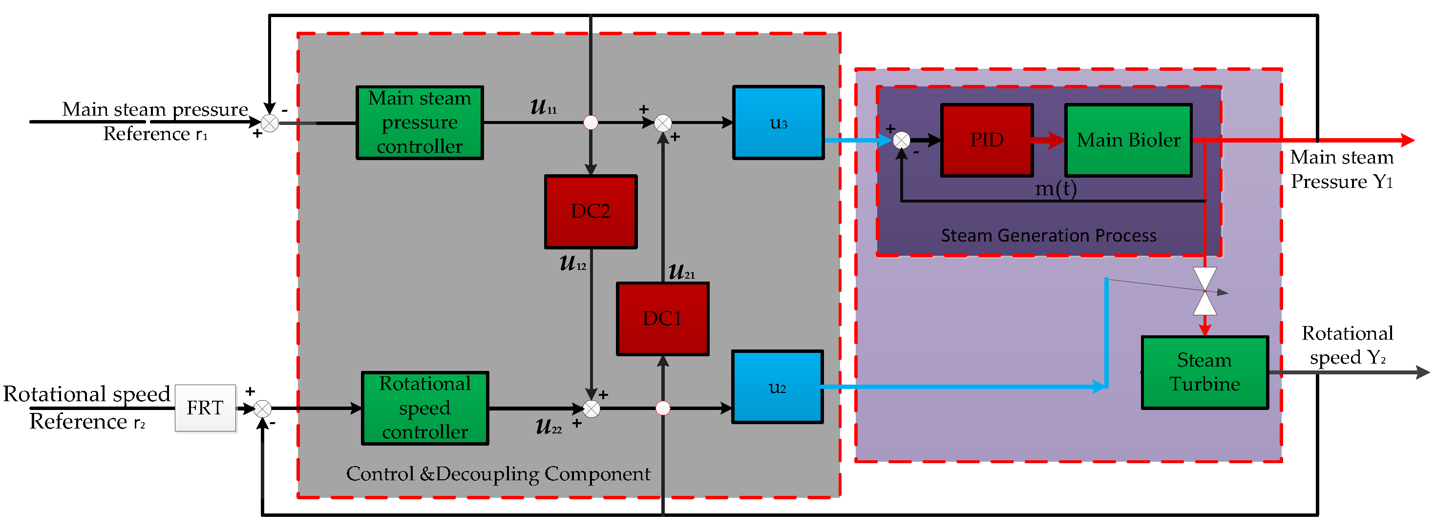
According to the above equations and Figure 2, the following coupling model of MBTS can be obtained:
d P d t = L 1 ( K 2 e τ 1 s ( T 1 s + 1 ) ( T 2 s + 1 ) u 1 ( s ) ) k v P c T sup u 2 d n 2 ( t ) d t = 2 k v P ( t ) T sup Δ h ( n ( t ) ) J u 2 ( t ) 2 ρ D 5 f 5 ( n ( t ) ) n 3 ( t ) J
According to Equation (1), the analytic relation between the fuel input u1(t) and the main steam flow m(t) is as follows:
m ( t ) = 0 t g ( t τ ) u 1 ( τ ) d τ
g ( t ) = K T 1 T 2 ( e t τ 1 T 1 e t τ 1 T 2 )
Substituting Equations (13a) into Equation (12), the coupling model of MBTS can be written in Equation (13c):
d P d t = 0 t g ( t τ ) u 1 ( τ ) d τ k v P c T sup u 2 d n 2 ( t ) d t = 2 k v P ( t ) T sup Δ h ( n ( t ) ) J u 2 ( t ) 2 ρ D 5 n 3 ( t ) f 5 ( n ( t ) ) J

2.2. Design of the IBICDC for the MBTS

2.2.1. The Control of the Steam Generation Process

The literatures on the decoupling control of MBTS are also scarce, which can only be seen in some academic conferences. And only a few literatures on decoupling control of steam power plant in the thermal power station in land can be seen in authoritative journals [1,4,5,6,7,8,10,11,12,37,38,39,40]. In [8,37,38,39,40], linear model predictive control (MPC) is used for the coupling problem. Most of the models used in [8,37,38,39,40] come from [2], or identified by neural network and fuzzy methods. Since MBTS in this paper is a non-linear strong coupling multi-operation system, MPC is no longer applicable, and the use of nonlinear model predictive control (NMPC) will produce new problems: (1) nonlinear models and multiple operating conditions in MBTS will make the optimization problem of NMPC a non-convex optimization problem, which will cause the sequential quadratic programming method no longer be applicable; (2) generally, the stability of NMPC usually achieved by making the terminal state of the system into a specified terminal constraint set (which can be equality constraints or inequality constraints), but the current NMPC terminal constraint set lacks an effective design method. In addition, it will increase the amount of calculation and calculation time for online optimization, which makes the optimal control input designing very difficult; (3) the input, output, and state constraints not only lead to a large amount of calculation and long calculation time for MPC to solve constraint optimization online, but also cannot obtain the analytic expression of the optimal control input, and the optimal control input often exceeds the allowable range of input constraints.
Literature [21] proposed a compensatory decoupling method based on the linear time-invariant system, but the MBTS system is a nonlinear system, and the transfer function matrix required by the decoupling method cannot be obtained. Therefore, this decoupling method is not applicable to MBTS. Literature [22] put forward a hierarchical fuzzy sliding-mode (HFSM) decoupling control method. However, because of its high dependence on the structural characteristics of the model, it cannot be applied in this research. In [23], nonlinear models were transformed into linear models by local linearization method (Taylor expansion), and the optimal decoupling method (minimize squared tracking error) was adopted to solve the coupling problem of the system, but there were multiple operating conditions in the MBTS system, which required local linearization of the model at multiple operating points and a switching mechanism. In literature [24] a robust decoupling precompensator was proposed for the transfer function matrix coupling system. Reference [25] presented a decoupled optimization technique using genetic algorithms (GAs), and a stable self-learning PID control scheme was proposed in [27], and the PID parameters were adapted by the Lyapunov method to minimize the squared tracking error. Similarly, reference [28] achieved decoupling by using a support vector machine.
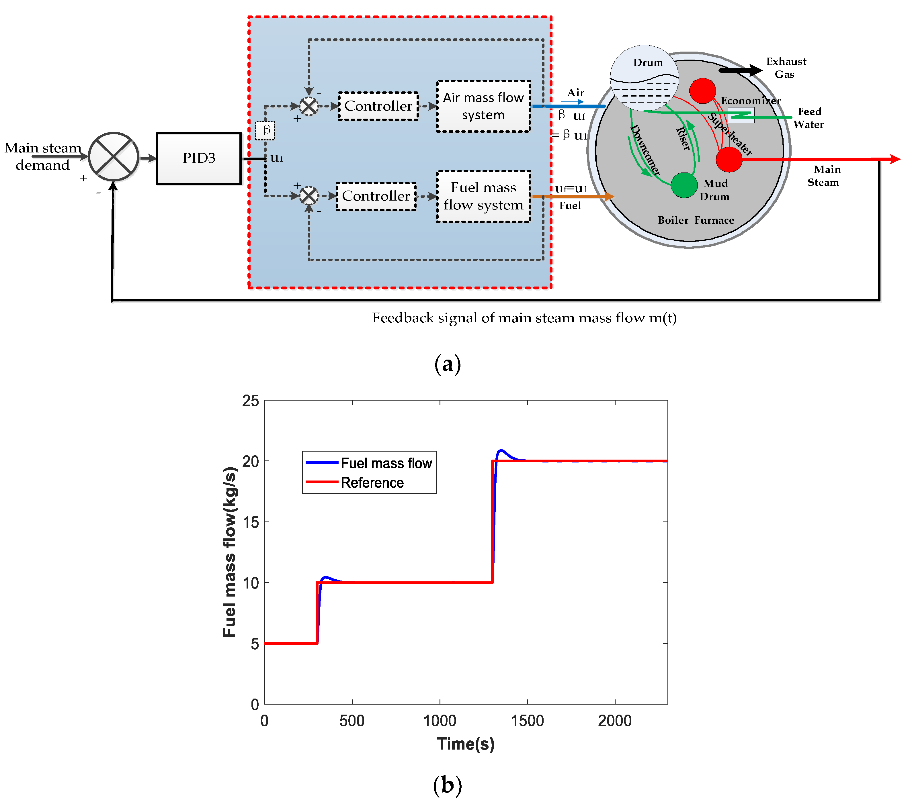
Reference [10,20] proposed a decoupling control algorithm based on the output feedback linearization, but there is a dynamic process when the control input is applied to the MBTS (for details, please refer to Equations (12) and (13)). As a result, this decoupling algorithm cannot be directly applied in this paper. To solve the coupling problem between torque and flux of induction motor, an adaptive state feedback linearized speed control algorithm is designed in [26]. Similar to the literatures [10,20], it is also difficult to apply this control algorithm directly in MBTS. Literature [29,30,31] presented an intelligent bi-cooperative decoupling controller inspired by the modulation mechanism of internal environment in human body, which is very useful for this study. However, like [10,20], this decoupling algorithm cannot be directly applied in MBTS. In order to solve this problem, the steam generation process is regarded as an inner control loop, and its input is fuel and output is steam flow. As shown in Equation (1), the model adopts a PID controller as follows.
The control system block diagram and simulation result of steam generation process is presented below.
Actually, the oxygen required for fuel combustion is supplied by air; in order to ensure sufficient burning, our group sets a definitive ratio β for oxygen entering the furnace, see Figure 3(a). The control input u1 of the PID controller is the reference signal of the fuel flow control loop, βu1 is the reference signal of the air flow control loop, and uf means the output of the fuel flow loop (the issues of the fuel flow loop and the air flow loop control are not discussed in the research, so uf = u1). PID controller parameters: KP = 0.7496; KI = 0.01578; KD = 3.3057.
u 1 = K P e m ( t ) + K I 0 t e m ( t ) d t + K D d e m ( t ) d t
The method was used to determine the PID controller parameters are the Ziegler-Nichols parameters tuning rules of PID method. em(t) is the error value between the main steam demand value and the main steam mass flow of MB. Then the coupling model of MBTS can be further expressed as:
{ d P ( t ) d t = m ( t ) c k v P ( t ) c T sup u 2 ( t ) d n 2 ( t ) d t = 2 k v P ( t ) T sup Δ h ( n ( t ) ) J u 2 ( t ) 2 ρ D 5 f 5 ( n ( t ) ) n 3 ( t ) J
Note: with a controller for the steam generation process, the item “m(t)” in Equation (14a) is the decoupling control input of the MBTS, and recorded as u3 as below:
{ d P ( t ) d t = u 3 ( t ) c k v P ( t ) c T sup u 2 ( t ) d n 2 ( t ) d t = 2 k v P ( t ) T sup Δ h ( n ( t ) ) J u 2 ( t ) 2 ρ D 5 f 5 ( n ( t ) ) n 3 ( t ) J
[ P ˙ N ˙ ] = [ f 11 ( P , N , u 3 , t ) + f 12 ( P , N , u 2 , t ) + f 13 ( P , N , t ) f 21 ( P , N , u 3 , t ) + f 22 ( P , N , u 2 , t ) + f 23 ( P , N , t ) ]
Using the Euler Discrete method, Equation (14c) can be written in discrete-time realization manner (the sample time is Ts):
[ P ( k ) N ( k ) ] = [ f 11 , k ( P , N , k ) f 12 , k ( P , N , k ) f 21 , k ( P , N , k ) f 22 , k ( P , N , k ) ] [ u 3 ( k 1 ) u 2 ( k 1 ) ] + [ f 13 , k ( P , N , k ) f 23 , k ( P , N , k ) ]
f 11 = 1 c , f 12 = k v P ( t ) c T sup u 2 ( t ) , f 13 = 0
f 21 = 0 , f 22 = 2 k v P ( t ) T sup Δ h ( N 1 / 2 ( t ) ) J u 2 ( t ) , f 23 = 2 ρ D 5 f 5 ( N 1 / 2 ( t ) ) N 3 / 2 ( t ) J
f 11 , k = T s c , f 12 , k = T s k v P ( k 1 ) c T sup , f 13 , k = P ( k 1 )
f 21 , k = 0 , f 22 , k = 2 T s k v P ( k 1 ) T sup Δ h ( N 1 / 2 ( k 1 ) ) J , f 23 , k = N ( k 1 ) 2 T s ρ D 5 f 5 ( N 1 / 2 ( k 1 ) ) N 3 / 2 ( k 1 ) J
where u3(t) denotes the steam mass flow of MB; u2(t) is the opening of the steam turbine governing valve; P(t) is the main steam pressure value of MB; N is n2(t).

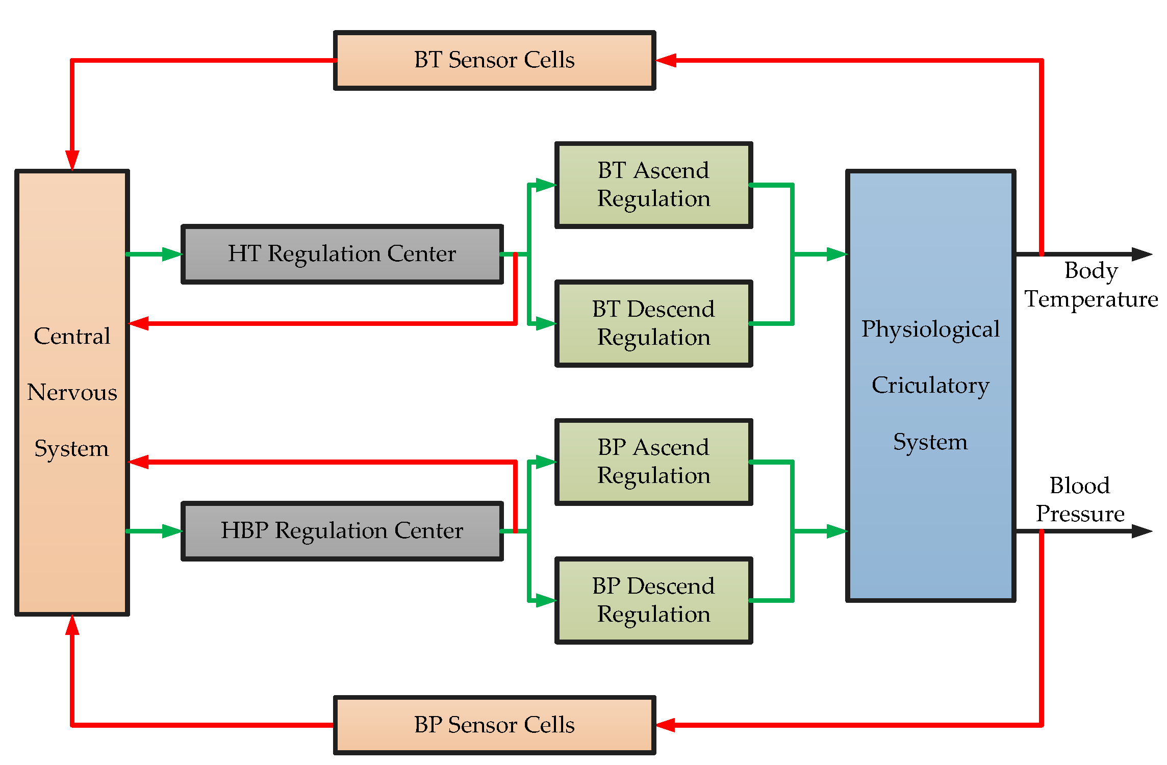
2.2.2. Neuroendocrine Regulation Principles (NERP) in the Human Body

In the human body, the biochemical systems, organs, and physiological metabolisms are not independent but interactive with each other [41]. Among these subsystems in the human body, the nervous system and endocrine system play much more important roles [30]. The nervous system and the endocrine system work cooperatively to establish a stable internal environment in the human body. Therefore, a stable internal environment is extremely critical to the normal physiological metabolisms [31,41].
The nervous system is the main regulating system in the human body. Under the direct or indirect manipulation of the nervous system, all the organs, systems, and all kinds of physiological metabolisms are not working alone. They are interconnected and act in close coordination, which makes the human body a whole and complete organism, and realizes and maintains the human life and behaviors.
The nervous system is divided into central nervous system and peripheral nervous system. The peripheral nervous system is distributed widely all over the body, and binds the brain and spinal cord with the other organs closely. This structure allows the central nervous system easy to acquire information of the inner and outer environments of the human body (afferent neuron transmit sensory information).
The conventional control system contains a controller, actuator, and plant. In the Figure 4, the nervous system consists of many organs, glands, sensors corresponding to components of the conventional control system. Hence, there remain similarities between the nervous system and conventional control system, and the nervous system principles can be applied to MBTS.

2.2.3. The Structure and Scheme of IBICDC

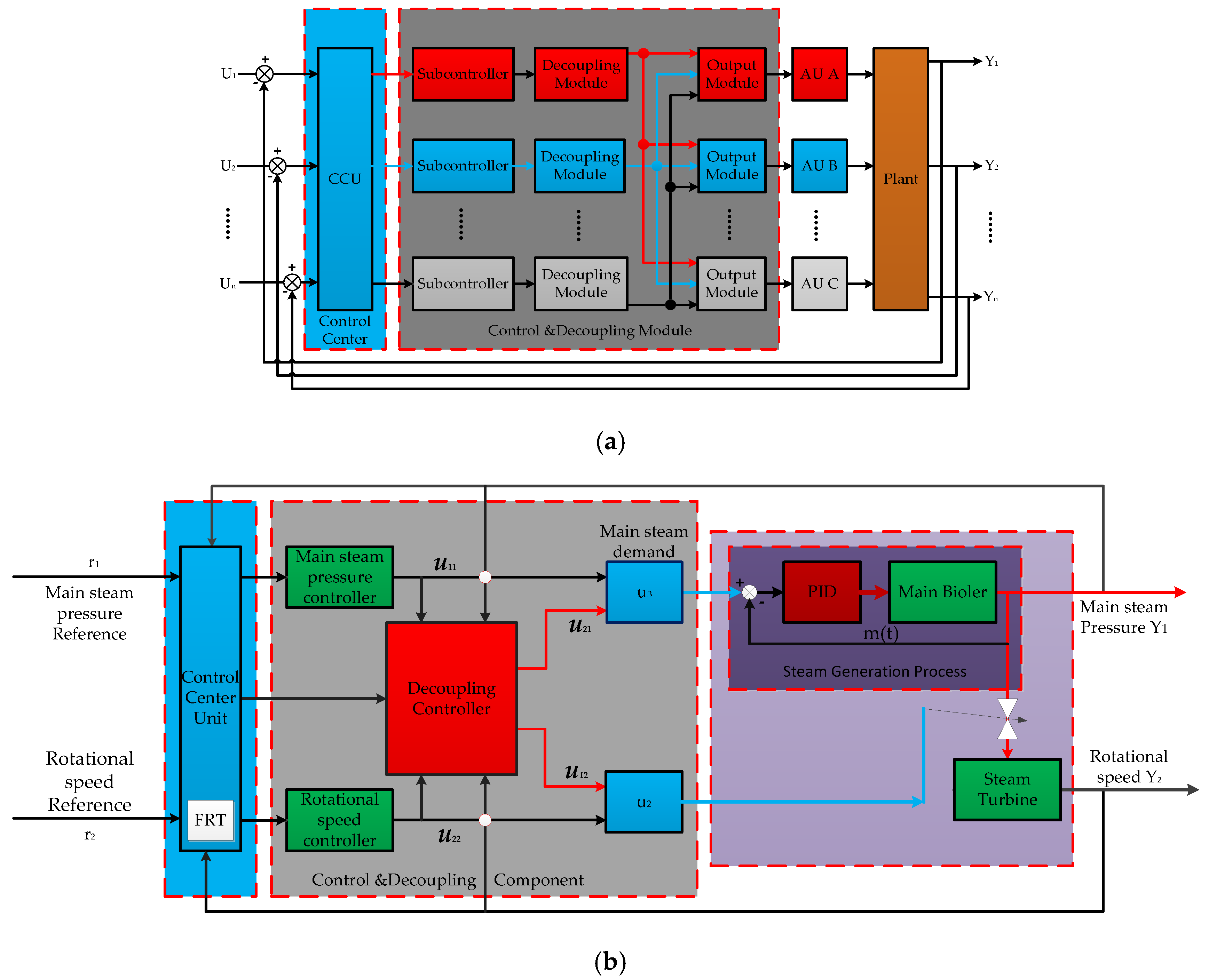
According to the neuroendocrine regulation principles in the human body, the IBICDC control system structure is shown in Figure 5, in which the decoupling coordination control algorithm IBICDC is divided into two parts [15].
Part I-basic part: This part contains two PID controllers, PID1 is for the main steam pressure P, and PID2 is for the N of MSTP; Part II-cooperative decoupling controller: The function of this part is mainly to decoupling the coupling influence between the main steam pressure control loop and the rotational speed control loop, eliminating the violent oscillation between the two loops.
According to the Equation (14), it can be obtained that the main steam pressure consists of two parts: 1. the main steam generated by MB increases the main steam pressure value; 2. the main steam consumed by MSTP reduces the main steam pressure value.
{ P ˙ = P ˙ P + P ˙ N = f 11 u 3 + f 12 u 2 P k = P P , k + P N , k = f 11 , k u 3 , k + f 12 , k u 2 , k + f 12 , k
{ U P , k = P I D 1 ( e P , k , k ) U N , k = P I D 2 ( e N , k , k )
{ e P , k = P r e f e r , k P k e N , k = N r e f e r , k N k
where: UP,k and UN,k are the control signals of PID1 and PID2, respectively.
{ P I D 1 ( e P , k , k ) = K P 1 ( e P , k e P , k 1 ) + K I 1 e P , k + K D 1 ( e P , k 2 e P , k 1 + e P , k 2 ) P I D 2 ( e N , k , k ) = K P 2 ( e N , k e N , k 1 ) + K I 2 e N , k + K D 2 ( e N , k 2 e N , k 1 + e N , k 2 )
The design of the IBICDC decoupling coordination control algorithm:
According to the Equations (14) and (15):
[ P ˙ N ˙ ] = [ 0 0 0 f 24 ] [ P N ] + [ f 11 f 12 0 f 22 ] [ u 3 u 2 ]
{ u 3 = u 11 + u 21 u 2 = u 12 + u 22 f 24 = ρ D 5 N 1 / 2 f 5 ( N 1 / 2 ) J { u 11 = U P u 22 = U N
where u3 denotes the main steam of MB; u2 is the opening of the steam valve of MSTP; u11 is UP,k−1; u12 is the decoupling coordination to MSTP; u21 is the decoupling coordination to MB; u22 is UN,k−1.
The following focuses on the calculation of u3 and u2; the main steam pressure P should remain unchanged, so dP/dt = 0 in Equation (19):
P ˙ = f 11 u 3 + f 12 u 2
P ˙ = f 11 u 3 + f 12 u 2 = 0
As dP/dt = 0, which means P is a constant value, transforming Equation (22) into a time-discrete form:
f 11 , k ( Δ u 11 , k + Δ u 21 , k ) + f 12 , k ( Δ u 12 , k + Δ u 22 , k ) = 0
When MBTS is running in the steady state operation, the parameters of the whole system can be considered as constant value, which implies P/dt = 0, dN/dt = 0, Δu11 = 0, Δu21 = 0, Δu12 = 0, and Δu22 = 0. When the operating condition of the system is changing, the rotational speed of MSTP needs to be changed. The main steam pressure of MB changes with the rotational speed. When the main steam pressure value changes sharply and exhibits large fluctuations, the decoupling coordination controller begins to work, which means dP/dt = 0, dN/dt ≠ 0 (ΔN ≠ 0), Δu11 = 0, Δu21 ≠ 0, Δu12 = 0, and Δu22 ≠ 0. According to Equation (23), we can have:
f 11 Δ u 21 + f 12 Δ u 22 = 0 f 11 , k Δ u 21 , k + f 12 , k Δ u 22 , k = 0
Δ u 21 , k = f 12 , k Δ u 22 , k f 11 , k
In the same way, when the main steam pressure of MB changes: dP/dt ≠ 0, dN/dt = 0(ΔN = 0), we can calculate Δu12:
Δ u 12 = f 21 Δ u 11 f 22 Δ u 12 , k = f 21 , k Δ u 11 , k f 22 , k
According to the principles of the human internal environment, information on changes of environmental parameters inside and outside the human body is collected by the nerve network. However, the reference trajectory (equivalent to the external parameters of human body) and the variation information of the rotational speed (equivalent to the internal parameters of human body) in the MBTS are not reflected in Equation (15). Therefore, in order to achieve a better decoupling system, drastic changes in the main steam pressure should be reduced, the change information of reference trajectory and the MSTP rotational speed to the decoupling controller need to be added. The decoupling controller is represented by:
Δ u 21 , k = 1 f 11 , k ( a 12 f ( N r e f e r , k ) + a 11 f ( N k ) + f 12 , k Δ u 22 , k )
In the same way, when the main steam pressure of MB changes: dP/dt ≠ 0, dN/dt = 0 (ΔN = 0), we can calculate Δu12:
Δ u 12 , k = 1 f 22 , k ( a 21 f ( N r e f e r ) + a 22 f ( N k ) + f 21 , k Δ u 11 , k )
f ( N r e f e r , k ) = d 11 N r e f e r , k + d 12 d N r e f e r , k d t f ( N k ) = d 21 N k + d 22 N k d t
Therefore, u21 can offset the coupling influence of the MSTP rotational speed loop on the main steam pressure loop. Moreover, u12 can offset the coupling influence of the main steam pressure loop on the rotational speed control loop, in turn.

2.2.4. The Flexible Reference Trajectory (FRT) Scheme

A critical mechanism of the human neuroendocrine regulation system is slow regulation; when the external interference alters the human body internal environment parameters. The buffering effect of the internal environment in the human body prevents parameters from changing dramatically in a moment as drastically as a step or pulse signal, but smoothly and slowly deviates from the normal value. Then the human body regulation mechanism can adjust the changing parameters gradually to the normal value. In this process, parameters slowly and steadily move from the deviation value to the normal value in a smooth manner, instead of in a drastic manner (which can result in overshoot and waste body matter and energy). Hence, in order to embody this mechanism in the IBICDC, a FRT is introduced in this research. FRT replaces the step reference signal in the control input, which ensures the output can slowly and smoothly follow FRT during the state switching process. The details are described as follows:
According to Equation (14c), initial conditions of the main steam pressure P and rotational speed N are P(0) and N(0), respectively.
[ P ( k ) N ( k ) ] = [ i = 1 k A i i = 2 k A i A k 2 A k 1 A k ] U + ( i = 1 k A i ) [ f 13 , 0 f 23 , 0 ]
In order to achieve a simpler formulary of Equation (29), let A k = [ f 11 , k f 12 , k 0 f 22 , k ] ; F0=[f13,0f23,0];
Φ = [ Φ 1 Φ 2 ] = [ i = 1 k A i i = 2 k A i A k 2 A k 1 A k ] ; Γ = [ Γ 1 Γ 2 ] = i = 1 k A i .
U=[UP,0, UN,0, UP,1, UN,1,…, UP,k-1, UN,k-1]T
Then, Equation (29) can be transformed to:
P(k)=Φ1U+Γ1f13,0
N(k)=Φ2U+Γ2f23,0
In order to prove the coupling influence of the MSTP rotational speed control loop on the main steam pressure control loop can be reduced significantly under FRT. Taking the 2-norm of both sides of Equation (31), we can get:
P ( k ) = Φ 1 U 1 + Γ 1 F 0 N ( k ) = Φ 2 U 2 + Γ 2 f 23 , 0
Let f13,0 = 0, f23,0 = 0. Substituting (16)–(18) into (30):
U 1 = [ U P , 0 , U P , 1 , , U P , k 1 ] T = [ P I D 1 ( 0 ) , , P I D 1 ( k 1 ) ] T
where P I D 1 ( i ) = [ K P 1 K I 1 K D 1 ] [ 0 1 1 0 0 1 1 2 1 ] [ e P , i 2 e P , i 1 e P , i ] ; K = [ 0 1 1 0 0 1 1 2 1 ] ; KPID1 = [KP1KI1KD1].
U 1 = [ K P I D 1 K 0 0 0 K P I D 1 K 0 0 0 K P I D 1 K ] [ e P , 0 e P , 1 e P , k 1 ]
Let K P I D 1 = [ K P I D 1 K 0 0 0 K P I D 1 K 0 0 0 K P I D 1 K ] ; [ e P , 0 e P , 1 e P , k 1 ] = [ P r e f e r , 0 P 0 P r e f e r , 1 P 1 P r e f e r , k 1 P k 1 ] .
U 1 = K P I D 1 [ P r e f e r , 0 P 0 P r e f e r , 1 P 1 P r e f e r , k 1 P k 1 ] T
Similarly, it can be obtained:
U 2 = K P I D 2 [ N r e f e r , 0 N 0 N r e f e r , 1 N 1 N r e f e r , k 1 N k 1 ] T
where K P I D 2 = [ K P I D 2 K 0 0 0 K P I D 2 K 0 0 0 K P I D 2 K ] .
Substituting (35) and (36) into (30):
U = [ K P I D 1 ( P r e f e r , 0 P 0 ) K P I D 2 ( N r e f e r , 0 N 0 ) K P I D 2 ( N r e f e r , k 1 N k 1 ) ] T
Psrefer,k = aPk−1 + bPrefer,k
Nsrefer,k = aNk−1 + bNrefer,k
e s P , k = P s r e f e r , k P k e s N , k = P s r e f e r , k P k
U s = [ K P I D 1 ( P s r e f e r , 0 P 0 ) K P I D 2 ( N s r e f e r , 0 N 0 ) K P I D 2 ( N s r e f e r , k 1 N k 1 ) ] T
where Psrefer,k, Nsrefer,k are the FRT of the main steam pressure P and rotational speed N, respectively; Prefer and Nrefer are the step reference signals of the system. a and b are the flexible factors, 0 < a < 1, 0 < b < 1, and a + b = 1.
Take the 2-norm to Equations (37), (38), and (39a) respectively:
U S max ( a , b ) U
Substituting (37) and (40) into (32):
P ( k ) = Φ 1 U S + Γ 1 F 0 Φ 1 U S + Γ 1 F 0 Φ 1 U S + Γ 1 F 0 Φ 1 U + Γ 1 F 0 N ( k ) = Φ 2 U S + Γ 2 F 0 Φ 2 U S + Γ 2 F 0 Φ 2 U S + Γ 2 F 0 Φ 2 U + Γ 2 F 0
It can be known that the control law obtained by introducing the FRT has a better control performance.

3. Simulations Results and Discussion

The load of MBTS can be divided into the following two types: steady state conditions and dynamic switching conditions. Steady state conditions: (1) high navigational speed condition; (2) medium navigational speed condition; (3) low navigational speed condition. Dynamic switching conditions: (1) high navigational speed directly reduces to low navigational speed conditions; (2) low navigational speed directly rises to high navigational speed conditions; (3) high navigational speed step-down condition; (4) low navigational speed step-rise condition.
The simulation in this paper is mainly for the dynamic switching conditions of MBTS during the navigational speed switching. The rotational speed of the MSTP at different working conditions in the simulations is 180 r/min in the high navigational speed condition, 120 r/min at medium navigational speed condition, and 60 r/min in the low navigational speed conditions. Therefore, four simulation conditions are set as follows: low navigational speed step-rising condition with MSTP rotational speed of 60 r/min→120 r/min→180 r/min; low navigational speed directly rising to high speed condition with MSTP rotational speed of 60 r/min→180 r/min; high navigational speed step-down condition with MSTP rotational speed 180 r/min→120 r/min→60 r/min; high navigational speed directly reducing to low speed condition with MSTP rotational speed 180 r/min to 60 r/min. In order to verify IBICDC, other methods such as: PID, PIDDC, and Intelligent PIDDC have also been performed. For more details see the Appendix B. All the parameters listed at Table 1.
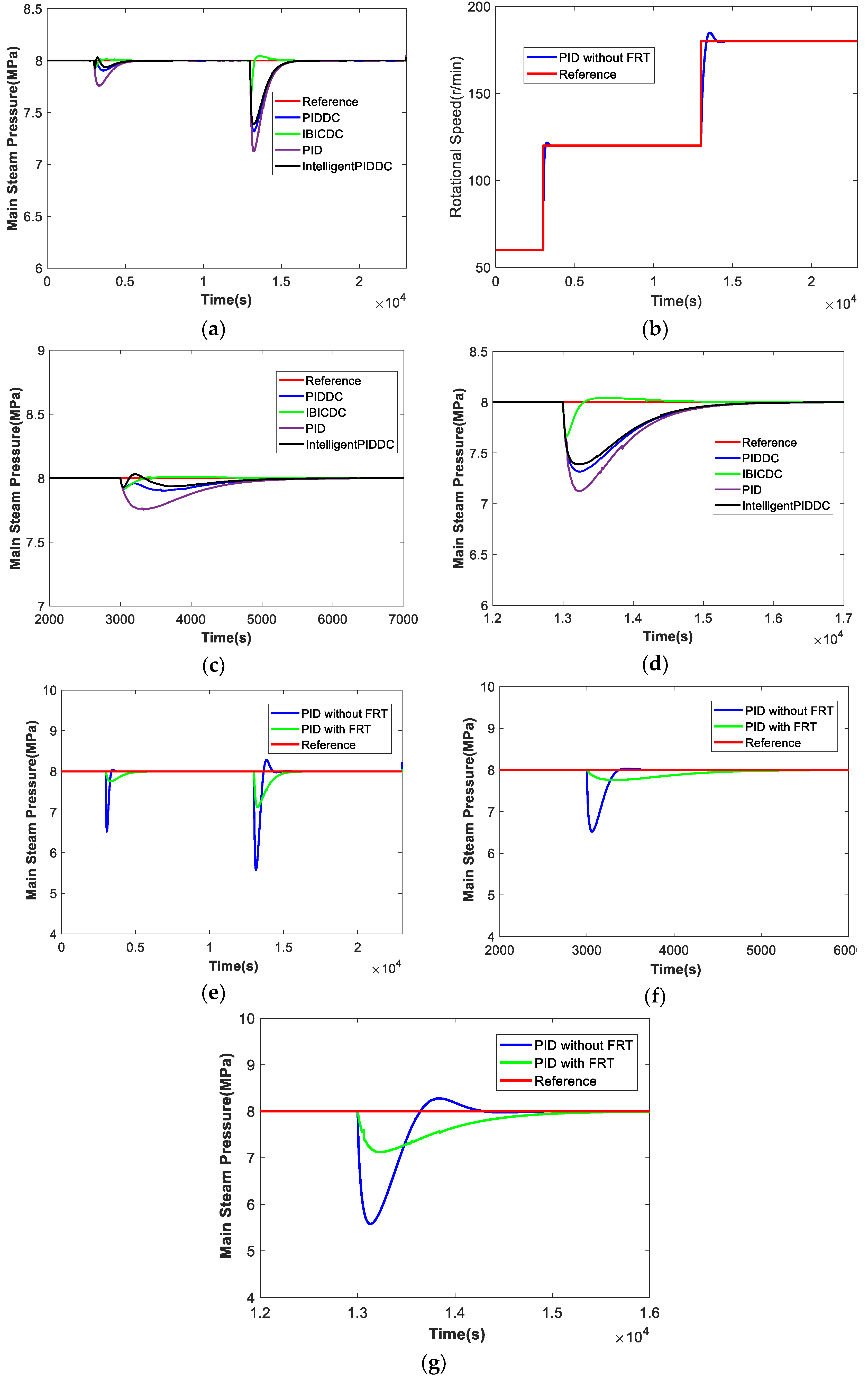
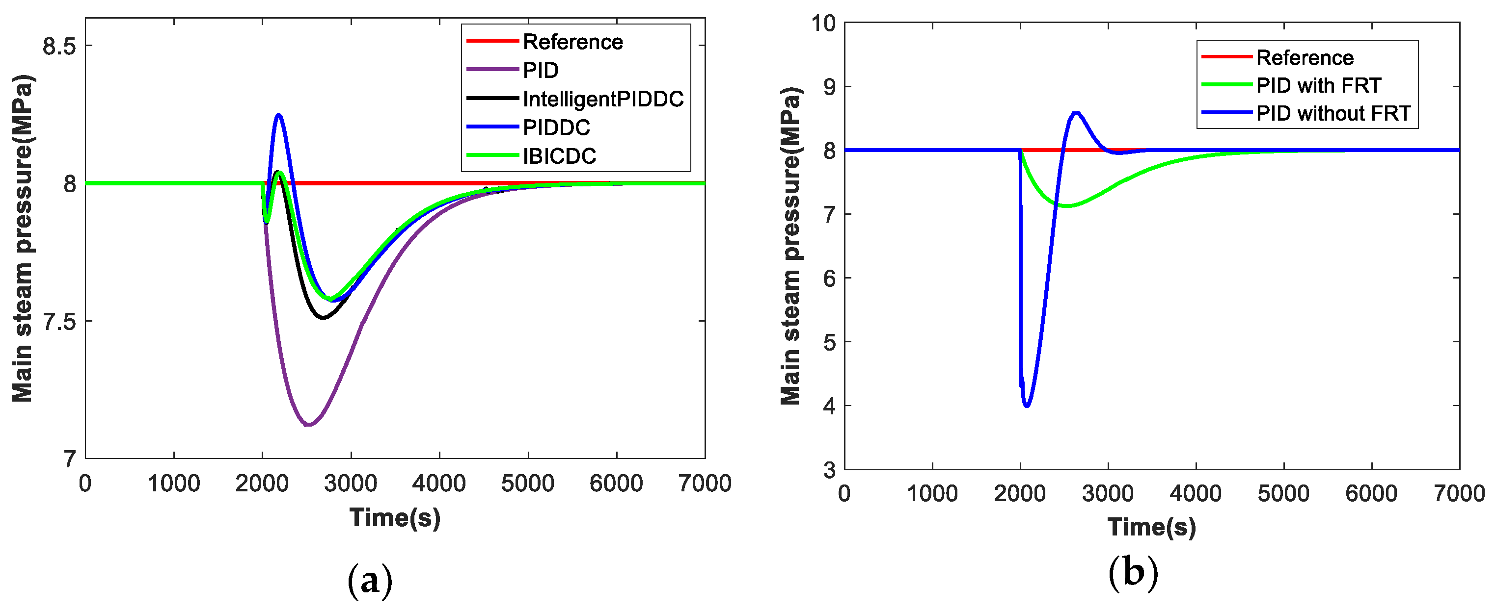
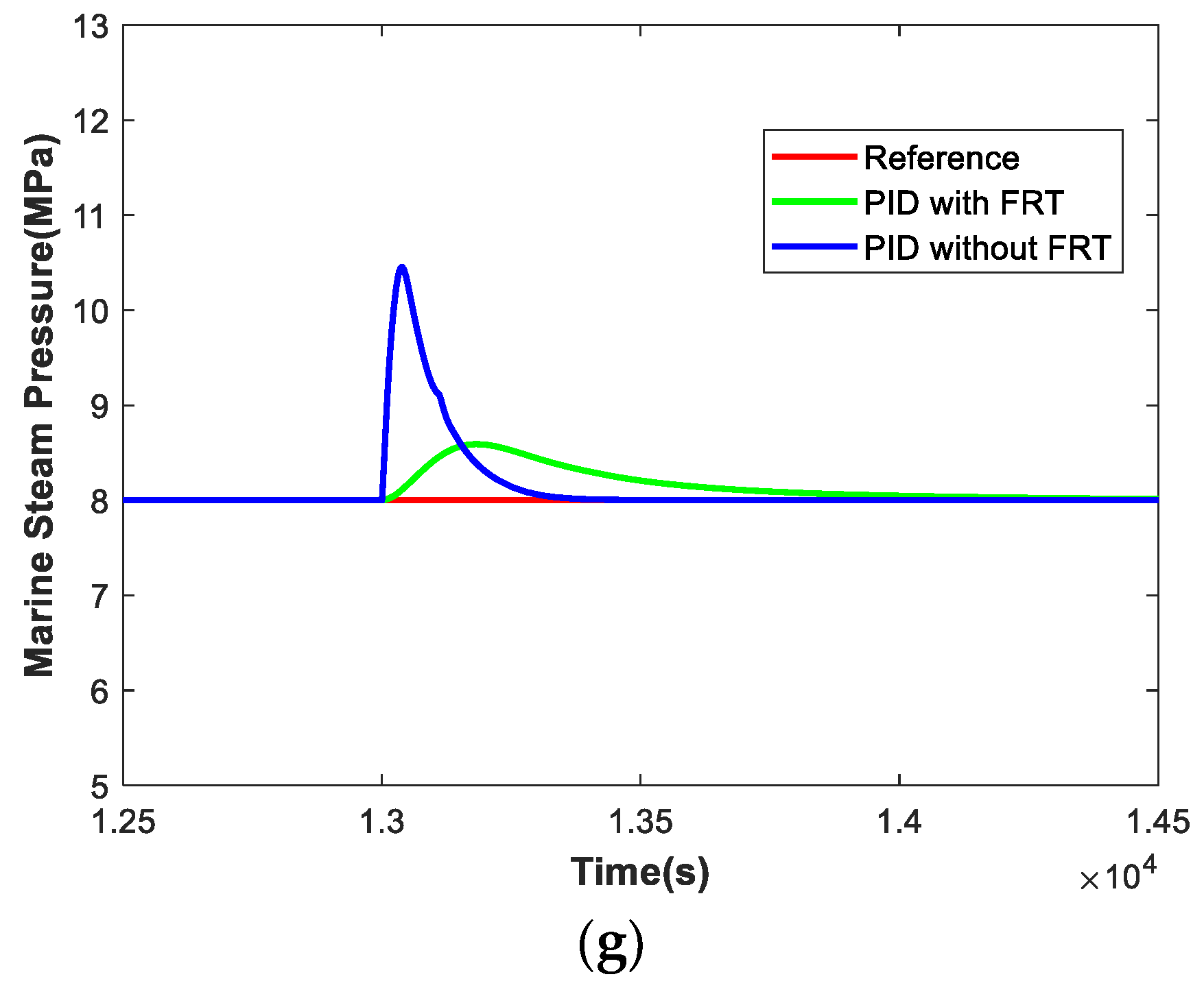
From Figure 6, Figure 7, Figure 8 and Figure 9, the following conclusions can be drawn:
1.The introduction of the FRT can greatly reduce the amplitude oscillation of the main steam pressure, which indicates that the FRT can buffer the coupling influence of the MSTP on the main steam pressure when the operating condition changes;
2.The PID control method can make the main steam pressure reach to the steady-state value when the operating condition changes, but the dynamic process control performance is very poor, and the main steam pressure changes sharply;
3.Compared with the PID control, the PIDDC method can eliminate the coupling influence on the main steam pressure to some extent, but the control performance is not ideal;
4.Compared with the PIDDC method, Intelligent PIDDC further eliminates the coupling influence of the main steam pressure, but the amplitude of the main steam pressure fluctuation is still relatively large;
5.The IBICDC introduces more information about the internal and external changes of the system, so that it can apply more effective control input, eliminate the coupling influence of the main steam pressure, and has a better dynamic control performance than the previous three methods.
Moreover, the simulation results show that although the PIDDC and Intelligent PIDDC control algorithms can also achieve steady-state response, the variation range of all the parameters are beyond the normal range obviously. So, the IBICDC coordinated control algorithm has a better control performance.

4. Conclusions

In this paper, an IBICDC control algorithm is presented based on the NERP of the human body, and applied to the coupling control problems of MBTS. The simulation results show that IBICDC can respond to the expected output quickly, reduce the coupling influence on the main steam pressure, and improve the MBTS control performance. IBICDC makes a smooth regulation with a smaller overshoot, which means less fuels consumption. Compared with other decoupling control methods, IBICDC has the advantages of simple structure, less computation, and easy implementation, so it is worth being applied in engineering. IBICDC can be applied in complicated multivariable process control systems, but many problems occur when applied to the motion control systems (such as ship track control, unmanned aerial vehicle, and unmanned submersibles, etc.). In this research, the FRT in IBICDC can be applied in other control systems with step reference as tracking trajectory, which is conducive to effectively reducing the overshoot and improving the control performance. In addition, in many cases, the control input of the system will exert constraint, and this will result in a great trouble to the controller design. The FRT method can be adopted to avoid such problem. The future work includes: (1) there is an astern working condition for the MSTP. However, this study does not verify the switching process of astern and forward working conditions. So, the next step is to solve the problem. (2) other control approaches based on optimization such as nonlinear model predictive control for this problem are with high research value, and our group is working on this approach.

Author Contributions

Conceptualization and supervision S.L. and B.Z.; methodology, S.L. B.Z., S.Z., L.Z., and L.W.; software, B.Z.; writing—original draft preparation, B.Z.; writing—review and editing, B.Z.; funding acquisition, S.L.

Funding

This work was supported by the National Natural Science Foundation of China subsidization project (51579047), the Natural Science Foundation of Heilongjiang Province (QC2017048), the Natural Science Foundation of Harbin (2016RAQXJ077), and the fundamental research funds for the central universities (3072019CF407).

Conflicts of Interest

The authors declare no conflict of interest.

Appendix A

In accordance with achievements by Martin-Hou:
P ( T , V ) = R T V b + j = 2 A j + B j T + C j T e 5.475 T C T ( V b ) j
In 2016, REN Tieliang, WAN Xue et al. simplified (A1) into:
P ( T , V ) = R T V b + j = 2 5 A j + B j T + C j T e 3 T C T ( V b ) j
In our study, the main steam pressure range is: [7MPa, 10MPa], the desire value of the main steam pressure is 8 MPa, the molar specific volume V = 1.0683047401 × 10⁻³, b = 6.6454139232 × 10⁻⁶. The molar specific volume V of steam is much larger than b value, so b in item (V-b) of the Equation is negligible and can be directly regarded as V, obtaining the simplified results in this paper as follows:
P ( T , V ) = R T V + j = 2 5 A j + B j T + C j T e 3 T C T V j
The derivative of the main steam pressure P to time t can be expressed as:
d P ( V ( t ) , T ( t ) ) d t = P ( V ( t ) , T ( t ) ) V ( t ) d V ( t ) d t + P ( V ( t ) , T ( t ) ) T ( t ) d T ( t ) d t
The steam temperature T = 529 °C is a fixed value, so there is dT(t)/dt = 0. Equation (A4) can be further simplified as:
d P ( V ( t ) , T ( t ) ) d t = P ( V ( t ) , T ( t ) ) V ( t ) d V ( t ) d t
According to Equation (A2), we have:
P ( V ( t ) , T ( t ) ) V ( t ) = R T V 2 ( t ) + 2 ( A 2 + B 2 T ( t ) + C 2 T ( t ) e 3 T C T ( t ) ) V 3 ( t ) + 3 ( A 3 + B 3 T ( t ) + C 3 T ( t ) e 3 T C T ( t ) ) V 4 ( t ) + 4 ( A 4 + B 4 T ( t ) + C 4 T ( t ) e 3 T C T ( t ) ) V 5 ( t ) + 5 ( A 5 + B 5 T ( t ) + C 5 T ( t ) e 3 T C T ( t ) ) V 6 ( t )
In the MB, there is V(t) = Me/ρ(t) that can be substituted into Equation (A6) to obtain:
d P ( V ( t ) , T ( t ) ) d t = ρ 2 ( t ) R T M e 2 2 ρ 3 ( t ) ( A 2 + B 2 T + C 2 T e 3 T C T ) M e 3 3 ρ 4 ( t ) ( A 3 + B 3 T + C 3 T e 3 T C T ) M e 4 4 ρ 5 ( t ) ( A 4 + B 4 T + C 4 T e 3 T C T ) M e 5 5 ρ 6 ( t ) ( A 5 + B 5 T + C 5 T e 3 T C T ) M e 6
d V ( t ) d t = d ( M e / ρ ( t ) ) d t = M e ρ 2 ( t ) d ρ ( t ) d t
ρ ( t ) = M ( t ) V t d ρ ( t ) d t = 1 V t d M ( t ) d t
where, M(t) is the steam mass in the steam header connecting MB and MSTP, Vt is the volume of steam in the main steam header, and Me is the molar mass of water molecules, ρ is the main steam density.
The derivative of the main steam mass in the header is:
d M ( t ) d t = m ( t ) f s ( t )
where, m(t) is the amount of steam entering to the header from MB, and fs(t) is the amount of steam consumed by the MSTP. It shows that:
d V ( t ) d t = M e ( m ( t ) f s ( t ) ) ρ 2 ( t ) V t
Substituted Equations (A7) and (A11) into Equation (A5):
d P ( t ) d t = [ R T M e + 2 ρ ( t ) ( A 2 + B 2 T + C 2 T e 3 T C T ) M e 2 + 3 ρ 2 ( t ) ( A 3 + B 3 T + C 3 T e 3 T C T ) M e 3 + 4 ρ 3 ( t ) ( A 4 + B 4 T + C 4 T e 3 T C T ) M e 4 + 5 ρ 4 ( t ) ( A 5 + B 5 T + C 5 T e 3 T C T ) M e 5 ] m ( t ) f s ( t ) V t
Then let:
1 c = [ R T M e + 2 ρ ( t ) ( A 2 + B 2 T + C 2 T e 3 T C T ) M e 2 + 3 ρ 2 ( t ) ( A 3 + B 3 T + C 3 T e 3 T C T ) M e 3 + 4 ρ 3 ( t ) ( A 4 + B 4 T + C 4 T e 3 T C T ( t ) ) M e 4 + 5 ρ 4 ( t ) ( A 5 + B 5 T + C 5 T e 3 T C T ) M e 5 ] / V t
Then Equation (A12) can be expressed as:
d P ( V ( t ) , T ) d t = m ( t ) f s ( t ) c
As for the ship, within the value range of the steam pressure, the value of c changes little, so it is regarded as a constant value, acquiring the equation below:
c d P ( t ) d t = m ( t ) f s ( t )

Appendix B

PID block diagram as follows:
Figure A1. PID block diagram of MBTS.
Energies 12 04659 g0a1
where, u3,k = PID1(k), u2,k = PID2(k).
{ P I D 1 ( k ) = K P 1 ( e s P , k e s P , k 1 ) + K I 1 e P , k + K D 1 ( e s P , k 2 e s P , k 1 + e s P , k 2 ) P I D 2 ( k ) = K P 2 ( e s N , k e s N , k 1 ) + K I 2 e s N , k + K D 2 ( e s N , k 2 e s N , k 1 + e s N , k 2 )
PIDDC adopts the feedback compensation decoupling control method, with block diagram as follows:
Figure A2. PIDDC block diagram of MBTS.
Energies 12 04659 g0a2
where u11,k = PID1(k), u22,k = PID2(k), u3(k) = u11,k + u21,k and u2(k) = u12,k + u22,k.
Δ u 21 , k = f 12 Δ u 22 , k f 11
Δ u 12 , k = f 21 Δ u 11 , k f 22
Intelligent PIDDC adopts fuzzy PID adaptive controller [42] based on PIDDC, with block diagram as follows:
Figure A3. Intelligent PIDDC block diagram of MBTS.
Energies 12 04659 g0a3
where, u11,k = PID1(k) + uF1,k, u22,k = PID2(k) + uF2,k, u3(k) = u11,k + u21,k and u2(k) = u12,k + u22,k. And uF1,k and uF2,k are generated by fuzzy principles.
The proposed IBICDC method, with block diagram as follows:
Figure A4. IBICDC block diagram of the MBTS.
Energies 12 04659 g0a4
where, u11,k = PID1(k), u22,k = PID2(k), u3(k) = u11,k + u21,k and u2(k) = u12,k + u22,k.
Δ u 21 , k = 1 f 11 ( a 12 f ( N s r e f e r , k ) + a 11 f ( N k ) + f 12 Δ u 22 , k )
Δ u 12 , k = 1 f 22 ( a 21 f ( N s r e f e r , k ) + a 22 f ( N k ) + f 21 Δ u 11 , k )
f ( N s r e f e r , k ) = d 11 N s r e f e r , k + d 12 d N s r e f e r , k d t f ( N k ) = d 21 N k + d 22 N k d t

References

  1. Yu, T.; Chan, K.W.; Tong, J.P.; Zhou, B.; Li, D.H. Coordinated robust nonlinear boiler-turbine-generator control systems via approximate dynamic feedback linearization. J. Process Control 2010, 20, 365–374. [Google Scholar] [CrossRef]
  2. Bell, R.D.; Åström, K.J. Dynamics models for boiler-turbine alternator units: Data logs and parameter estimation for a 160 MW unit. Dept. Autom. Control Lund Inst. Technol. Lund Sweden Tech. Rep. 1987, 3192, 1–137. [Google Scholar]
  3. Åström, K.J.; Bell, R.D. Drum-boiler dynamics. Automatica 2000, 36, 363–378. [Google Scholar] [CrossRef]
  4. Wei, L.; Fang, F. H∞-LQR-Based Coordinated Control for Large Coal-Fired Boiler–Turbine Generation Units. IEEE Trans. Ind. Electron. 2017, 64, 5212–5221. [Google Scholar] [CrossRef]
  5. Maffezzoni, C. Boiler-turbine dynamics in power-plant control. Control Eng. Pract. 1997, 5, 301–312. [Google Scholar] [CrossRef]
  6. Goto, S.; Nakamura, M.; Matsumura, S. Automatic realization of human experience for controlling variable-pressure boilers. Control Eng. Pract. 2002, 10, 15–22. [Google Scholar] [CrossRef]
  7. Chai, T.Y.; Yue, H.; Bai, Y. Intelligent control of coal-pulverizing systems with ball-tube mill. In Proceedings of the IFAC 14th Triennial World Congress, Beijing, China, 11 September 1999; pp. 97–102. [Google Scholar]
  8. Liu, X.J.; Guan, P.; Chan, C.W. Nonlinear multivariable power plant coordinate control by constrained predictive scheme. IEEE Trans. Control Syst. Technol. 2010, 18, 1116–1125. [Google Scholar] [CrossRef]
  9. Chen, H.Y.; Ye, R.; Wang, X.D.; Lu, R.G. Cooperative Control of Power System Load and Frequency by Using Differential Games. IEEE Trans. Control Syst. Technol. 2015, 23, 882–897. [Google Scholar] [CrossRef]
  10. Alamoodi, N.; Daoutidis, P. Nonlinear Decoupling Control with Deadtime Compensation for Multirange Operation of Steam Power Plants. IEEE Trans. Control Syst. Technol. 2016, 24, 341–348. [Google Scholar] [CrossRef]
  11. Li, S.Y.; Liu, H.B.; Cai, W.J.; Soh, Y.-C.; Xie, L.H. A New Coordinated Control Strategy for Boiler-Turbine System of Coal-Fired Power Plant. IEEE Trans. Control Syst. Technol. 2005, 13, 943–955. [Google Scholar]
  12. Liu, H.B.; Li, S.Y.; Chai, T.Y. Intelligent decoupling control of power plant main steam pressure and power output. Int. J. Elect. Power Energy Syst. 2003, 25, 809–819. [Google Scholar] [CrossRef]
  13. Åström, K.J.; Eklund, K. A simple non-linear drum boiler model. Int. J. Control 1975, 22, 739–740. [Google Scholar] [CrossRef] [Green Version]
  14. U.S. Energy Information Administration. Annual Energy Outlook 2019 with projections to 2050; Energy Information Administration: Washington, DC, USA, 2019.
  15. Ding, Y.S.; Liang, X.; Hao, K.R.; Wang, H.P. An Intelligent Cooperative Decoupling Controller for Coagulation Bath in Polyacrylonitrile Carbon Fiber Production. IEEE Trans. Control Syst. Technol. 2013, 21, 467–479. [Google Scholar] [CrossRef]
  16. Falb, P.L.; Wolovich, W.A. Decoupling in design and synthesis of multivariable control systems. IEEE Trans. Autom. Control 1967, 12, 651–669. [Google Scholar] [CrossRef] [Green Version]
  17. Ghosh, A.; Das, S.K. Open-loop decoupling of MIMO plants. IEEE Trans. Autom. Control 2009, 54, 1977–1981. [Google Scholar] [CrossRef]
  18. Marino, R.; Cinili, F. Input-output decoupling control by measurement feedback in four-wheel-steering vehicles. IEEE Trans. Control Syst. Technol. 2009, 17, 1163–1172. [Google Scholar] [CrossRef]
  19. Michioka, C.; Sakamoto, T.; Ichikawa, O.; Chiba, A.; Fukao, T. A decoupling control method of reluctance-type bearingless motors considering magnetic saturation. IEEE Trans. Ind. Appl. 1996, 32, 1204–1210. [Google Scholar] [CrossRef]
  20. Chien, T.L.; Chen, C.C.; Huang, C.J. Feedback linearization control and its application to MIMO cancer immunotherapy. IEEE Trans. Control Syst. Technol. 2010, 18, 953–961. [Google Scholar] [CrossRef]
  21. Malabre, M.; Torres-Munoz, J.A. Block decoupling by precompensation revisited. IEEE Trans. Autom. Control 2007, 52, 922–925. [Google Scholar] [CrossRef]
  22. Lin, C.M.; Mon, Y.J. Decoupling control by hierarchical fuzzy sliding-mode controller. IEEE Trans. Control Syst. Technol. 2005, 13, 593–598. [Google Scholar] [CrossRef]
  23. Fu, Y.; Chai, T.Y. Intelligent decoupling control of nonlinear multivariable systems and its application to a wind tunnel system. IEEE Trans. Control Syst. Technol. 2009, 17, 1376–1384. [Google Scholar] [CrossRef]
  24. Chunghtai, S.S.; Wang, H. A high-integrity multivariable robust control with application to a process rig. IEEE Trans. Control Syst. Technol. 2007, 15, 775–785. [Google Scholar] [CrossRef]
  25. Zhang, J.; Chung, H.S.H.L.; Lo, W.L.; Hui, S.Y.; Wu, A.K.-M. Implementation of a decoupled optimization technique for design of switching regulators using genetic algorithms. IEEE Trans. Power Electron. 2001, 16, 752–763. [Google Scholar] [CrossRef]
  26. Rashed, M.; McConnell, P.F.A.; Stronach, A.F. Nonlinear adaptive state-feedback speed control of a voltage-fed induction motor with varying parameters. IEEE Trans. Ind. Appl. 2006, 42, 723–732. [Google Scholar] [CrossRef]
  27. Yu, D.L.; Chang, T.K.; Yu, D.W. A stable self-learning PID control for multivariable time varying systems. Control Eng. Pract. 2007, 15, 1577–1587. [Google Scholar] [CrossRef]
  28. Quan, Y.; Yang, J. Optimal decoupling control system using kernel method. J. Syst. Eng. Electron. 2004, 15, 364–370. [Google Scholar]
  29. Ding, Y.S.; Liu, B.; Ren, L.H. A decoupling controller based on the inverse control and the bi-regulation principle of growth hormone. Dyn. Contin. Discret. Impuls. Syst. Ser. B 2007, 14, 679–694. [Google Scholar]
  30. Ding, Y.S.; Liu, B. An intelligent bi-cooperative decoupling control approach based on modulation mechanism of internal environment in body. IEEE Trans. Control Syst. Technol. 2011, 19, 692–698. [Google Scholar] [CrossRef]
  31. Liu, B.; Ding, Y.S.; Wang, J.H. An intelligent controller inspired by bi-cooperative modulation mechanism. In Proceedings of the 2011 Seventh International Conference on Natural Computation, Shanghai, China, 26–28 July 2011; pp. 1711–1715. [Google Scholar]
  32. Wu, M.; Yan, J.; She, J.H.; Cao, W.H. Intelligent decoupling control of gas collection process of multiple asymmetric coke ovens. IEEE Trans. Ind. Electron. 2009, 56, 2782–2792. [Google Scholar]
  33. Martin, J.J.; Hou, Y.C. Development of an equation of state for gases. Aiche J. 1955, 1, 142–151. [Google Scholar] [CrossRef] [Green Version]
  34. The International Association for the Properties of Water and Steam. Release on the IAPWS Industrial Formulation 1997 for the Thermodynamic Properties of Water and Steam; The International Association for the Properties of Water and Steam: Erlangen, Germany, 1997. [Google Scholar]
  35. Tupper, E.C.; Rawson, K.J. Basic Ship Theory; Butterworth-Heinemann: Oxford, UK, 2001. [Google Scholar]
  36. Carlton, J.S. Marine Propellers and Propulsion; Butterworth–Heinemann: Oxford, UK, 1994. [Google Scholar]
  37. Peng, H.; Ozaki, T.; Haggan-Ozaki, V.; Toyoda, Y. A nonlinear exponential ARX model-based multivariable generalized predictive control strategy for thermal power plants. IEEE Trans. Control Syst. Technol. 2002, 10, 256–262. [Google Scholar] [CrossRef]
  38. Katebi, M.R.; Johnson, M.A. Predictive control design for large-scale systems. Automatica 1997, 33, 421–425. [Google Scholar] [CrossRef]
  39. Ordys, A.W.; Kock, P. Constrained predictive control for multivariable systems with application to power systems. Int. J. Robust Nonlinear Control 1999, 9, 781–797. [Google Scholar] [CrossRef]
  40. Prasad, G.; Swidenbank, E.; Hogg, B.W. A neural net model-based multivariable long-range predictive control strategy applied thermal power plant control. IEEE Trans. Energy Convers. 1998, 13, 176–182. [Google Scholar] [CrossRef]
  41. Schulkin, J. Allostasis, Homeostasis, and the Costs of Physiological Adaptation; Cambridge University Press: New York, NY, USA, 2004. [Google Scholar]
  42. Chen, G.R.; Trung, T.P. Introduction to Fuzzy Sets, Fuzzy Logic, and Fuzzy Control Systems; CRC Press: Boca Raton, FL, USA; London, UK; New York, NY, USA; Washington, DC, USA, 2000. [Google Scholar]
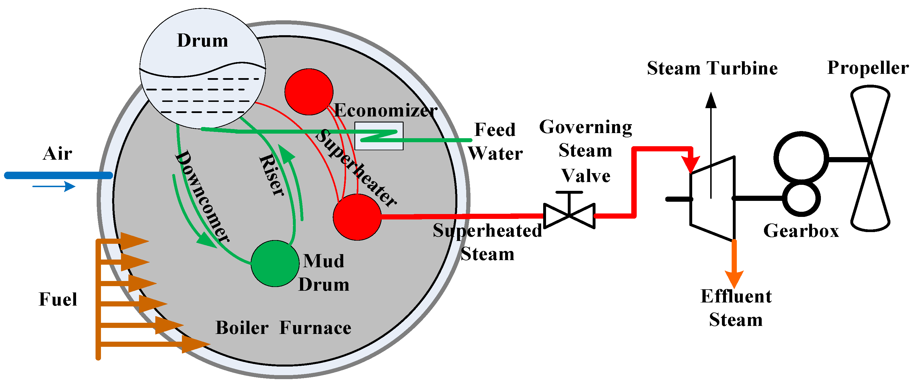
Figure 1. The main structure of marine boiler-turbine system (MBTS).
Energies 12 04659 g001
Figure 2. Block diagram of MBTS.
Energies 12 04659 g002
Figure 3. (a) Control system block diagram, (b) simulation result diagram of steam generation process.
Energies 12 04659 g003
Figure 4. Neuroendocrine regulation principles (NERP) in the human body.
Energies 12 04659 g004
Figure 5. (a) System structure of the intelligent bio-inspired cooperative decoupling control strategy (IBICDC), (b) IBICDC structure of the MBTS.
Energies 12 04659 g005
Figure 6. Low navigational speed step-rise condition of 60 r/min→120 r/min→180 r/min.(a) The marine steam pressure of the four decoupling control methods with FRT; (b) Rotational speed of PIDDC without FRT; (c) Zoom of (a) at the time 2000 s; (d) Zoom of (a) at the time 12,000 s; (e) The marine steam pressure of PID; (f) Zoom of (e) at the time 2000 s; (g) Zoom of (e) at the time 12,000 s.
Energies 12 04659 g006
Figure 7. Low navigational speed directly raises to high speed conditions of 60 r/min→180 r/min. (a) The marine steam pressure of PID with and without FRT; (b) The marine steam pressure of the four decoupling control methods with FRT.
Energies 12 04659 g007
Figure 8. The high navigational speed step-down condition with 180 r/min→120 r/min→60 r/min. (a) The marine steam pressure of the four decoupling control methods with FRT; (b) Rotational speed of PIDDC without FRT; (c) Zoom of (a) at the time 2000 s; (d) Zoom of (a) at the time 12,000 s; (e) The marine steam pressure of PID; (f) Zoom of (e) at the time 2000 s; (g) Zoom of (e) at the time 12,000 s.
Energies 12 04659 g008aEnergies 12 04659 g008b
Figure 9. High navigational speed directly reduces to low speed conditions 180 r/min to 60 r/min.(a) The marine steam pressure of PID with and without FRT; (b) The marine steam pressure of the four decoupling control methods with FRT.
Energies 12 04659 g009
Table 1. Parameters of MBTS.
SymbolValueSI-Unit
K117.0455
T1150s
T26s
Ts100s
kv300.5713
c10.7801MPa/kg
Tsup529°C
J2304.3748kg·m2
ρ1.0 × 10³kg/m3
a0.4
b0.6
a111
a121
a210.065
a220.065
d110.083
d120
d211
d220.0231
KP11.2992
KI10.01587
KD112.02301
KP20.001
KI24.7703 × 10-5
KD20.000011