Article

Adaptive Robust Control System for Axial Flux Permanent Magnet Synchronous Motor of Electric Medium Bus Based on Torque Optimal Distribution Method

School of Mechatronic Engineering and Automation, Shanghai University, Baoshan District, Shanghai 200444, China
*
Author to whom correspondence should be addressed.
Energies 2019, 12(24), 4681; https://doi.org/10.3390/en12244681
Submission received: 19 November 2019 / Revised: 6 December 2019 / Accepted: 7 December 2019 / Published: 9 December 2019
(This article belongs to the Special Issue Advances in Rotating Electric Machines)

Abstract

:
In this paper, an adaptive robust drive control system for an axial flux permanent magnet synchronous motor of an electric medium-sized bus based on the optimal torque distribution method is studied. The drive control system is mainly divided into two parts. First, a torque distribution method is proposed. The optimal torque distribution method based on particle swarm optimization algorithm is used to increase the high efficiency interval of the system and apply it to the energy feedback braking. Secondly, in order to reduce the nonlinear disturbance of the system and improve the accuracy of the unified control, this paper models and studies the vector system based on adaptive robust control. Finally, the whole drive control system is modeled, simulated and experimented. The simulation and experimental results show that the torque distribution method proposed in this paper can effectively increase the high-efficiency running time of the electric medium bus, and improve the shortcomings of insufficient mileage of the electric medium-sized bus. The use of a current controller based on adaptive robust control improves the control accuracy of the drive system and can effectively suppress the disturbances generated by it.

Graphical Abstract

1. Introduction

The passenger capacity of medium bus is generally 9–20, which is suitable for small and medium-size cities. With the increasing awareness of greenhouse gas emissions, the emergence of electric buses can meet the call for energy conservation and emission reduction [1]. Compared with the internal combustion engine powered medium bus, the electric medium bus have many advantages. For example, they have low vibration noise, simple structure, high power transmission efficiency, easy vehicle layout, and excellent power performance [2,3]. The selection of pure electric medium bus drive motors must meet the vehicle’s dynamic requirements, such as maximum speed, acceleration performance, and maximum grade [4]. Among a variety of vehicle drive motors, permanent magnet synchronous motors (PMSMs) have many applications [5,6]. Among them, the axial flux permanent magnet synchronous motors (AFPMSMs) have the advantages of low speed, large torque and high energy density, and are more suitable for use in an electric medium bus with a larger passenger capacity. Double stator-single rotor AFPMSM (two-disc AFPMSM) has better heat dissipation and larger rated torque. Therefore, the two-disc AFPMSM is selected as the driving motor for electric medium bus in this paper.
The two-disc AFPMSM can be equivalent to two PMSMs connected coaxially, and for electric medium-sized buses, there is only one given torque, so this paper involves the problem of multi-motor torque distribution. At present, the commonly used torque distribution method is mainly applied to distributed drive vehicles. Compared with the conventional central direct drive electric vehicles, the drive motors of the various wheels of the distributed drive electric vehicle can be independently controlled, and the torque of each wheel can be distributed in any proportion within its capability range. The energy can be controlled by properly distributing the wheel torque so that the motor works as much as possible in the high efficiency range. The author of [7] proposed a multi-objective optimization method that considers system efficiency and safety for torque distribution. The authors of [8] mainly use torque distribution to enable micro electric vehicles to improve powertrain efficiency. The authors of [9] used the optimal vehicle state estimation method for directional tire torque distribution. In this paper, a torque optimal allocation method is proposed for the purpose of efficiency optimization. The particle swarm optimization algorithm is used to optimize the torque distribution mathematical model to obtain the optimal torque distribution solution. In addition, regenerative braking is one of the most effective ways to extend the durability of electric vehicles [10,11,12]. In order to further increase the cruising range, this paper applies the previously described optimal torque distribution method to the braking situation.
In addition, due to the large number of passengers in medium bus, some researchers have studied the safety and stability of driving. Authors of [13,14,15,16] studied the safety-structure from the structure of the medium bus, among which authors of [13,14] focused on studying the strength of conventional bus structures under operating conditions, authors of [15,16] studied the crashworthiness under rollover accident.
In addition, the research on control systems is mainly divided into two categories, motor design and optimization and motor control. The research on AFPMSM mainly focuses on the optimization of the motor model. The authors of [17] used the combined solution of Maxwell’s equations and magnetic equivalent circuits to model the AFPMSM analytically. The authors of [18] used an auxiliary multi-objective optimization algorithm to optimize the design of AFPMSM with dual rotor and single stator. This paper studies the anti-interference and current tracking capabilities of the driving system of medium-sized buses from the perspective of drive control. During the operation of the electric medium bus, due to the complicated operating environment, it will encounter various nonlinear disturbances. Adaptive robust control is used to overcome the effects of nonlinear disturbances, thereby improving tracking accuracy of the current loop. In the study of adaptive robust control, the authors of [19] used adaptive synthesis robust control strategies based on μ synthesis to resist the interference of high-frequency dynamic problems generated by the motor structure mode on linear motor control. The authors of [20] used neural networks to learn adaptive robust controllers to resist interference from unknown factors. The author of [21] used an adaptive robust controller based on extended disturbance observer to improve the control accuracy of linear motors. In this paper, adaptive robust control is applied to the drive control system of AFPMSM for anti-disturbance control.
This paper mainly studies the drive control system of electric medium bus. From the above, the drive control system is mainly divided into two parts. The first part mainly studies the torque distribution method, with the system’s highest working efficiency as the distribution target. The second part mainly studies the motor control part. In order to reduce the waveform ripple and improve the system control accuracy, this paper models and studies the adaptive robust control vector system. Finally, the above methods are simulated and the motor experiments and loading experiments are performed, and the results are summarized.

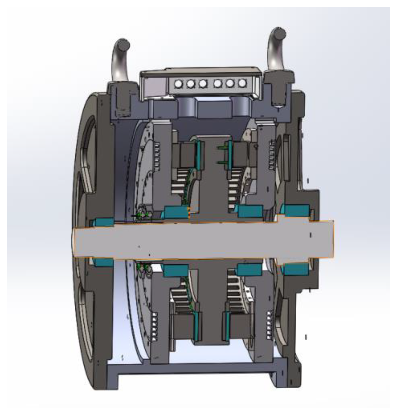
2. Two-Disc AFPMSM Mathematical Model

Compared with the traditional AFPMSM, the AFPMSMs with multi-disc structure improve the overall efficiency of the motor by adjusting the number of stators and rotors running [22]. Therefore, this paper takes the AFPMSM of double-stator-single-rotor structure as the research object, and establishes its mathematical model as the theoretical basis for deducing its control strategy. The structure of the dual-stator-single-rotor AFPMSM (also called double-disc AFPMSM) is shown in Figure 1.
In order to distinguish the two stators of the AFPMSM, they are respectively defined as the stator 1 and the stator 2. The simplified PMSMs are the motor 1 and the motor 2. For the motor 1 and the motor 2, a d-q axis rotating coordinate system is established, which is d1-q1 and d2-q2, and the coordinate system rotation speeds are ω1 and ω2, and the rotation directions are the same. Since the double disc AFPMSM shares one rotor and is coaxially connected, two mathematical models of the d-q axis rotating coordinate system can be established at the same time. The mathematical model of the AFPMSM is as follows.
Voltage equation:
{ u d 1 = R s 1 i d 1 + L d 1 d i d 1 d t ω 1 L q 1 i q 1 u q 1 = R s 1 i q 1 + L q 1 d i q 1 d t + ω 1 L d 1 i d 1 + ω 1 ψ f u d 2 = R s 2 i d 2 + L d 2 d i d 2 d t ω 2 L q 2 i q 2 u q 2 = R s 2 i q 2 + L q 2 d i q 2 d t + ω 2 L d 2 i d 2 + ω 2 ψ f ,
Magnetic chain equation:
{ ψ d 1 = L d 1 i d 1 + ψ f ψ q 1 = L q 1 i q 1 ψ d 2 = L d 2 i d 2 + ψ f ψ q 2 = L q 2 i q 2 ,
Torque equation:
{ T e 1 = 3 2 p [ ψ f i q 1 + ( L d 1 L q 1 ) i d 1 i q 1 ] T e 2 = 3 2 p [ ψ f i q 2 + ( L d 2 L q 2 ) i d 2 i q 2 ] ,
Equation of motion:
{ T e 1 T L 1 B ω 1 = J p d ω 1 d t T e 2 T L 2 B ω 2 = J p d ω 2 d t ,
In Equations (1)–(4), Rs1 and Rs2 are two stator resistances respectively, and ud1, uq1, ud2, and uq2 are d-q axis components of the winding voltage vectors of the stator 1 and the stator 2, id1, iq1, and id2. iq2 is the d-q axis component of the winding current vectors of the stator 1 and stator 2, Ld1, Lq1, Ld2, Lq2 are the d-q axis components of the winding inductances of the stator 1 and stator 2, ψd1, ψq1, ψd2, ψq2 are the d-q axis components of the winding flux of stator 1 and stator 2, Te1 and Te2 are the electromagnetic torques of the stator 1 and the stator 2, TL1 and TL2 are the load torques of the stator 1 and the stator 2, J is the moment of inertia, B is the viscosity coefficient, and TL is the load torque.
Since the two stators share one rotor, it can be approximated that the two motor modules are coaxially connected, so ωr1 = ωr2 = ωr can be obtained. According to the conclusion of coaxial connection, two equivalent motors can now be analyzed under the same d-q reference coordinate system. The two stators are structurally identical and symmetrical, therefore the stator resistances RS1 and RS2 are equal. According to the uniform air gap of the motor, it can be obtained that the direct-axis inductance and the cross-axis inductance of the two motors are equal. This article uses a hidden-pole motor, so it is also concluded that the inductance of the AC and DC axes is equal. At this time, the electromagnetic torque equation can be rewritten as:
T e = T e 1 + T e 2 = 3 2 p ψ f ( i q 1 + i q 2 ) ,
The equation of motion is:
T e T L B ω r = J p d ω r d t ,

3. Torque Optimal Distribution Method

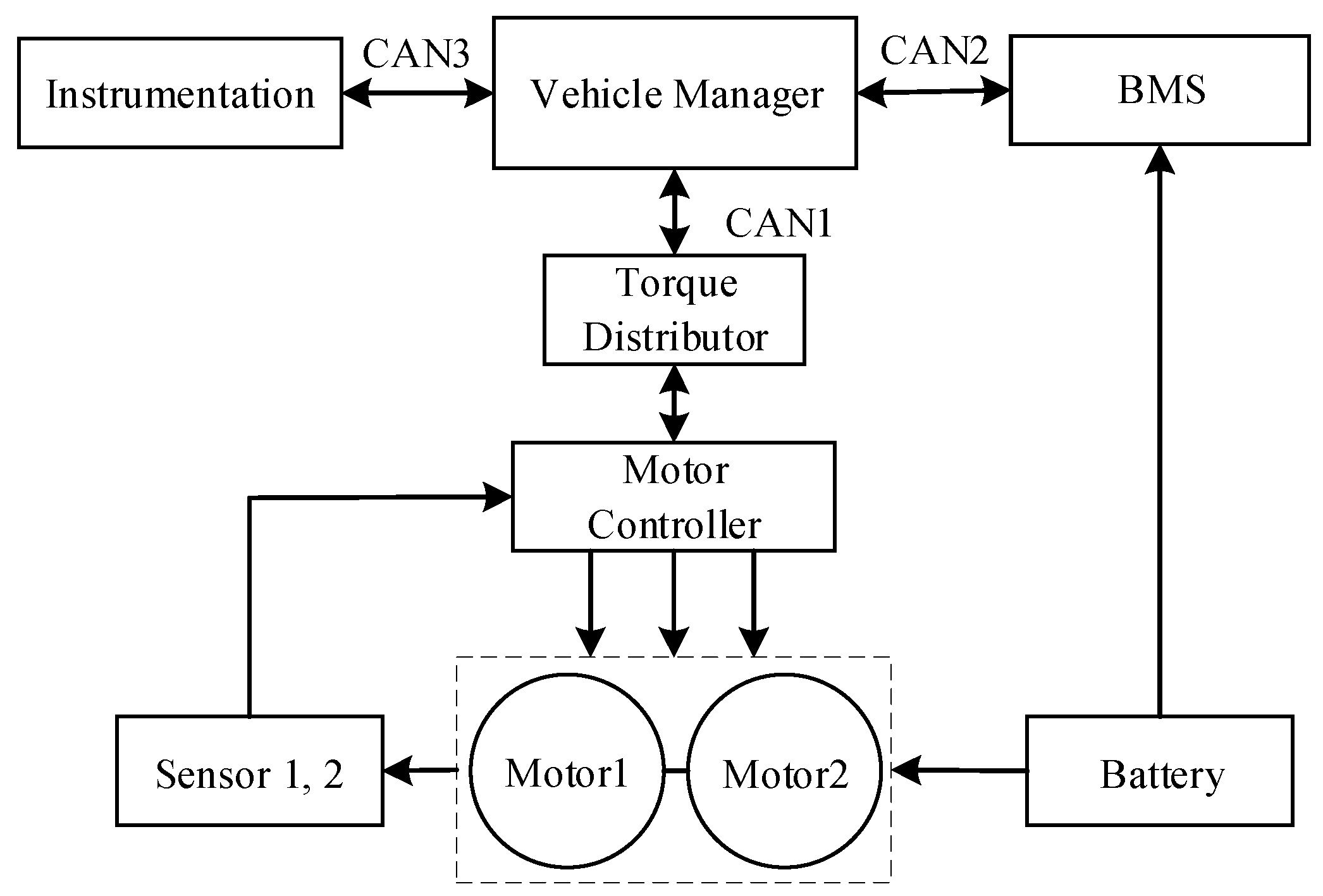
3.1. Dual Stator AFPMSM Drive System Topolgy

The traditional electric medium bus has only one motor drive system, and the vehicle manager only corresponds to one motor controller [23], and the two are connected by controller area network (CAN) communication. Unlike conventional two-motor electric vehicle drive systems, the dual-station AFPMSM needs to control two sets of stator windings. Although they are driven by separate inverters, the same motor controller can be used, so that the vehicle manager and the motor controller can be directly connected via controller area network (CAN) communication. In order to study the torque distribution method more conveniently, a torque distributor is added between the vehicle manager and the motor controller, and the torque is distributed to the motor through the torque distributor. The topology of the double-disc AFPMSM drive system is shown in Figure 2.
The general electric vehicle drive system only has a given torque Tm. The driving motor in this paper can be regarded as two motors after equivalent. Therefore, Tm needs to be allocated. The common method is to evenly distribute torque. In order to save battery power, an optimal torque distribution strategy based on particle swarm optimization is proposed, so that the system can operate in a high efficiency range. The system control block diagram is shown in Figure 3. According to the optimal torque distribution method, the distributed torques of the two motors are obtained, and then the motor control is performed.

3.2. Optimal Torque Distribution Control Method Based on Particle Swarm Optimization in Driving State

The torque optimal distribution strategy based on particle swarm optimization (PSO) is modeled as follows. Taking the double-disc AFPMSM for electric medium bus studied in this paper as an example, the total output torque is T, and the range is [0, 500 Nm]. The output torques of the two motor modules are T1 and T2, respectively, and the range is [0, 250 Nm], then:
T = T 1 + T 2 ,
Assuming that the mechanical angular velocity of the motor is ω, the output power of the two sets of motor modules is T1ω and T2ω, the input power is P1 and P2, and the operating efficiency is η1 and η2. Let T1 = a1T, T2 = a2T where a1 + a2 = 1, a1, a2 ∈ [0, 1]. Then the input power of the two motor is:
P 1 = T 1 ω η 1 = a 1 η 1 T 1 ω ,
P 2 = T 2 ω η 2 = a 2 η 2 T 2 ω ,
The total output power of the Motor Module is:
P o = T 1 ω + T 2 ω = T ω ,
The total input power is:
P i = P 1 + P 2 = ( a 1 η 1 + a 2 η 2 ) T ω ,
The total efficiency of the motor module is:
η = P o P i = T ω ( a 1 η 1 + a 2 η 2 ) T ω = 1 a 1 η 1 + a 2 η 2 ,
Assume:
f ( a 1 ) = a 1 η 1 , f ( a 2 ) = a 2 η 2 ,
It can be known from Equation (10) that the output power is constant during the operation of the electric medium bus and it is only necessary to reduce the total input power to improve the system efficiency. If the maximum value of η is required, that is, the minimum value of f(a1) + f(a2) is obtained.
Let
A = f ( a 1 ) + f ( a 2 ) ,
Then the problem translates into how the two sets of motor modules are assigned torque ratios for a given torque so that the value of A is minimized.
For Equation (14), when one of the torque distribution ratios a1 or a2 is determined, the value of A can be determined. However, the speed and torque at a certain moment are not involved in the Equation (14). In the optimization using the particle swarm optimization algorithm, the optimal distribution must be obtained based on the total given torque and speed. Therefore, the three-dimensional model of f(a1), the total torque command T, and the current rotational speed n can be obtained by data fitting. Since the two sets of motor modules are identical, the efficiency values are the same under different speeds and torques, so only the total torque command T is required to be the x-axis, and the rotational speed n is the y-axis. The value of f(a1) is calculated as the z-axis for all torque distribution ratios and corresponding efficiencies at different speeds and torques. The three-dimensional model is shown in Figure 4.When the torque distribution system inputs the torque and the rotational speed at any time, any value of f(a1) will have a certain value of f(a2) corresponding to it on the z-axis, so that the value of A under all torque distribution ratios can be calculated. The optimization of the PSO algorithm is to find the smallest one of all fitness functions in the three-dimensional stereogram model, and output the corresponding ratio of a1 and a2 to achieve the optimal torque distribution.
Through the analysis above, A = f(a1) + f(a2) can be used as fitness function, so the fitness function is designed as follows:
min A = f ( a 1 ) + f ( a 2 ) ,
In a search space of a D-dimensional parameter, the population size of the particles is Size. Each particle represents a candidate solution to the solution space, where the position of the i-th (1 ≤ iSize) particle in the entire solution space is represented as Xi and the velocity is represented as Vi. The optimal solution generated by the i-th particle from the initial to the current iteration number search is the individual extremum pi, and the current optimal solution of the entire population is BestS. Size particles are randomly generated, and the position matrix and velocity matrix of the initial population are randomly generated. The learning factors are set as c1 and c2, the maximum evolution algebra is G, and g is the current evolutionary algebra. The equation for the velocity and position of a particle in the solution space is as follows:
V i k g + 1 = w ( t ) × V i g + c 1 r 1 ( p i g X i g ) + c 2 r 2 ( B e s t S i g X i g ) ,
X i g + 1 = X i g + V i g + 1 ,
Among them, g = 1,2,…,G, I = 1,2,…,Size, r1 and r2 are random numbers from 0 to 1; c1 is a local learning factor, and c2 is a global learning factor, generally c2 is larger and w(t) is the inertia weight. The particle swarm optimization algorithm has the advantages of strong local search ability, fast calculation speed, and few parameters. However, during the running process, the particle swarm has strong convergence in the local, and it is easy to ignore all and fall into the local optimal solution [24]. In view of the shortcomings of the particle swarm algorithm, the inertia weight w(t) is added to the velocity term, which represents the ability of the particle to update the velocity, which has a great influence on the convergence and accuracy of the whole algorithm. A larger w(t) can improve the global search ability of the algorithm, while a smaller w(t) can improve the local search ability of the algorithm, so the value of w(t) should be decremented during the iterative process, which allows the particle to strike a balance between its search ability and convergence speed. The value of w(t) is determined according to Equation (18).
w ( t ) = w ( t ) max w max w min k max × k ,
In the equation, wmax represents the initial weight, wmin represents the final weight, k represents the current iteration number of particles, and kmax represents the maximum iteration number of particles. The particle swarm optimization is easy to converge too early and fall into local optimum, which makes it impossible to obtain global optimum solution. Combining with the requirements of speed control for electric vehicles, this paper improves the particle swarm optimization algorithm. The inertia weight is determined by the exponential decrement method, as defined by Equation (19).
w = w max ( w min w max ) 1 / ( 1 + 10 k / k max ) ,
In the initial stage, w is larger, and has a strong ability to search in a wide range. In the later stage, w is smaller and has a strong ability to search in a small range, thereby improving the performance of the particle swarm algorithm as a whole. At the same time, in order to avoid premature convergence of the algorithm, the learning factor is dynamically adjusted, as shown in Equation (20):
{ c 1 = 2 sin k π k max c 2 = 1 + sin k π k max ,
In the early stage of population search, c1 is larger and c2 is smaller, which facilitates the particle to learn its own optimal solution and improves the global search ability. In the later stage of population search, c2 is larger and c1 is smaller, which facilitates the population to move closer to the global optimal solution and enhances the local optimization performance.

3.3. Energy Feedback Brake Control Based on Optimal Torque Distribution Method

For electric medium bus, in order to further improve the cruising range, the energy feedback brake will be added to the vehicle. It not only saves energy, but also solves the problem that the electric medium bus has a short driving range of one charge, and can also improve the braking performance of the car and reduce the friction loss of the brake pad when the car brakes.
In this paper, the energy feedback brake control is carried out under the condition that the battery is safely charged, the rotation speed is not too low, and the power generation power is in the safe interval. Since the motor provides braking torque in the energy feedback state, the torque optimal control problem of the two sets of motor modules is involved. It is known in the foregoing studies that reasonable torque distribution can improve system efficiency. This conclusion is also applicable in the case of energy feedback. Therefore, in order to further improve the endurance of electric mid-size passenger cars, the optimal torque distribution strategy based on particle swarm optimization is also applied to improve the power generation efficiency of the motor. The basic block diagram of the system incorporating energy feedback is shown in Figure 5. The three-dimensional perspective of the braking mode obtained by the particle swarm optimization algorithm is shown in Figure 6.

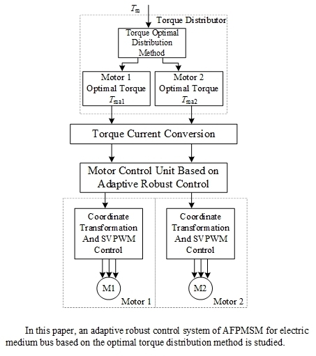
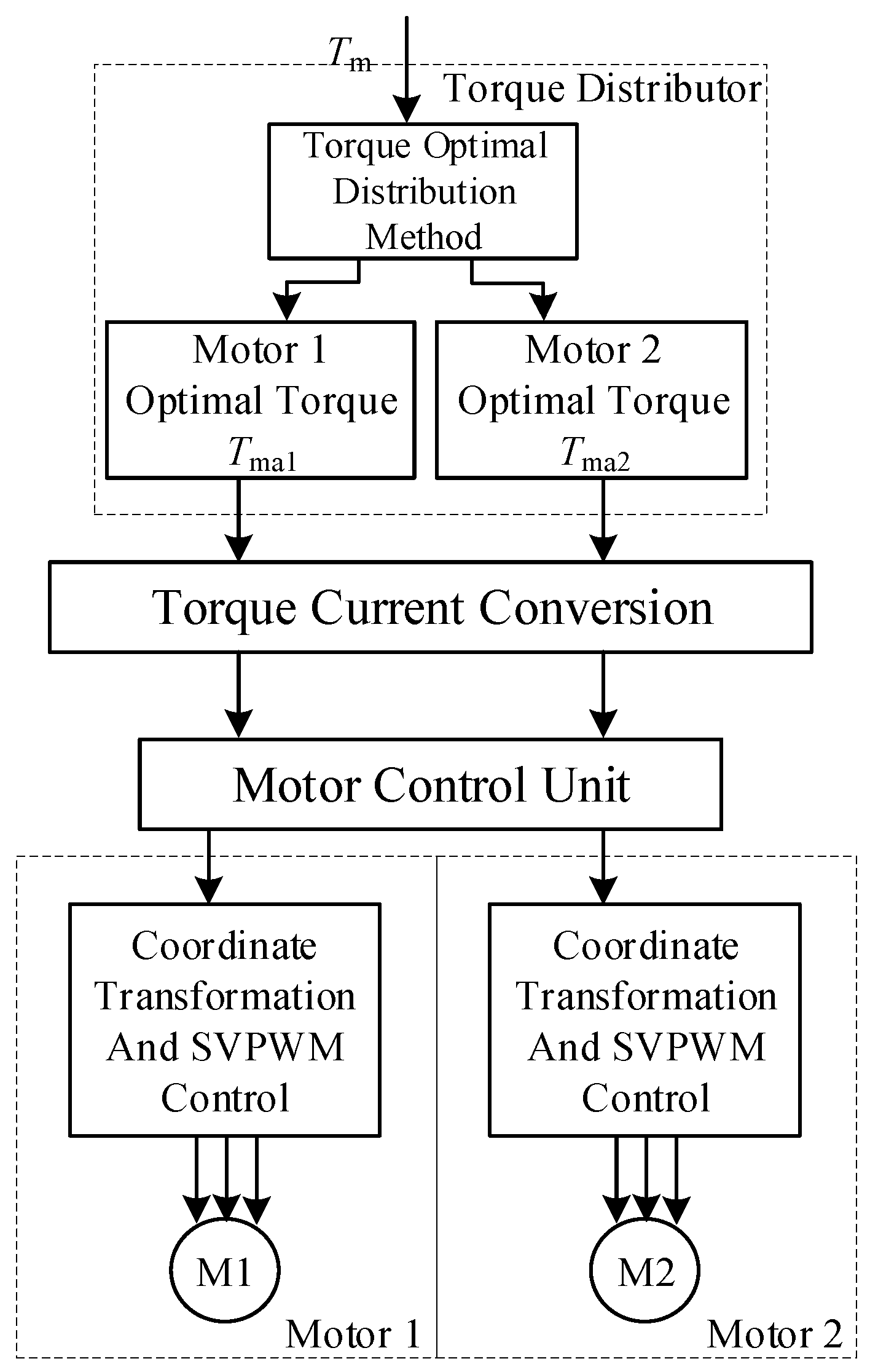
4. Electric Medium Passenger Bus Vector Control System Based on Adaptive Robust Current Control

Compared with the application of motors in other aspects, the motor drive system of electric medium-sized buses has higher requirements for the current following ability and control accuracy of the motor. During the operation of electric medium-sized buses, due to the complicated operating environment, it will encounter various non-linear disturbances, resulting in current and torque ripples in the system. Therefore, this paper chooses to study from the perspective of control, and uses adaptive robust control to overcome the effects of nonlinear disturbances, thereby improving the tracking accuracy of the current loop.
According to Equation (1), a voltage model containing non-ideal back-emf can be obtained as shown in Equation (21).
L d d t i q = u q R i q e q + Δ q ,
where eq is the non-ideal back-EMF, and Δq is the sum of the deviation voltages caused by all nonlinear disturbances.
Assume that the non-ideal back EMF model is:
e q = S ¯ e K e ,
where in S ¯ e represents a wave function containing a fundamental wave and a 6th harmonic, Ke represents a back EMF coefficient matrix. Their expressions are shown in Equations (23) and (24), respectively.
S ¯ e = 3 2 ω e [ 1   cos ( 6 σ e ) ] ,
K e = [ K q 1   K q 6 ] T ,
Bringing Equation (22) into Equation (21), the following equation of state can be obtained:
L d d t i q = u q R i q S ¯ e K e + Δ q ,
To establish a standard adaptive robust control model, let x ˙ = d d t i q , let γT = Se and σ = Ke.
Define the amount of virtual control u ¯ as:
u ¯ = u q R i q ,
where uq is the actual output of the controller and Riq is calculated from the known amount and the feedback amount.
Substituting the above assumption and Equation (26) into Equation (25), Equation (26) is obtained as shown below.
L x ˙ = u ¯ + γ T σ + Δ q ,
The adaptive robust current controller designed in this paper makes the output of the double-disc AFPMSM model overcome the effects of non-ideal back EMF and other nonlinear disturbances. The tracking error with the expected value xd is as small as possible.
It can be seen from the equation of state, Equation (27) that the previously designed double-disc AFPMSM model clearly includes parameter uncertainties and nonlinear disturbances. Adaptive robust control can compensate the uncertainty in the system through the design of adaptive law, and synthesize the robust control law to overcome the influence of nonlinear disturbance, so it is suitable for the design of PMSM current controller. According to Equations (27) and (28) can be obtained.
u ¯ = L x ˙ γ T σ Δ q ,
The control law form of the adaptive robust controller is as shown in Equation (29).
u ¯ = u a + u r ,
where ua is the compensation term for adaptive control, which can be expressed as:
u a = L x ˙ d γ T σ ^ ,
where x ˙ d is the differential of the expected value of the q-axis current and σ ^ is the estimated value of the unknown parameter σ.
ur is a robust control term and can be expressed as:
u r = u r 1 + u r 2 ,
In Equation (31), ur1 is a linear proportional feedback term and ur1 = –kr1z, kr1 is a proportional coefficient, and z = x – xd represents a tracking error. According to the control law represented by Equations (28) and (29), the dynamic equation of the system tracking error is:
L z ˙ u r 1 = u r 2 [ γ T σ ˜ Δ q ] ,
where σ ˜ is the parameter estimation bias and σ ˜ = σ ^ - σ , ur2 is the robust control term. According to the robust control principle, the design requirements are:
{ z u r 2 0 z { u r 2 [ γ T σ ˜ Δ q ] } ε ,
In the above equation, ε represents any positive integer, the first condition can be guaranteed to be naturally dissipated, and the second condition indicates that ur2 can suppress nonlinear disturbance, modeling error and estimation error of adaptive parameters. There are many ways to select ur2 that meet the conditions [19]. The most common one is:
{ u r 2 = 1 4 ε h 2 z h = | γ T | | σ max σ min | + Δ q max ,
It can be known from the control law in Equation (29) and the tracking error dynamic in Equation (32) that the tracking performance of the adaptive robust controller depends on the design of the robust control term ur. Since the adaptive law design is synthesized by tracking error, the parameter projection method is used to modify the adaptive law [20]. Therefore, the adaptive law of adaptive robust control is expressed as:
σ ^ ˙ = Pr o j ( Γ γ z ) ,
where Γ is a diagonal adaptive law matrix, and Proj(λ) is a projection operator, which can be expressed as:
Pr o j ( λ ) = { 0 , if { σ ^ = σ min   and   λ < 0 σ ^ = σ max and   λ > 0 λ , others ,
When using the control law of Equation (29) and the adaptive law of Equation (35), the adaptive robust current control block diagram is shown in Figure 7.

5. Simulation and Experimental Results

5.1. Drive System Simulation

A two-disc AFPMSM simulation system is set up, and the current controller adopts adaptive robust control method and PI control, respectively. Finally, compare the current tracking performance of the two controllers. The current controller adopts the control strategy of id = 0, the d-axis current adopts PI controller, the q-axis current adopts adaptive robust controller, the given current iq* is 150 A, and the iq current response waveform is shown in Figure 8. The three-phase current waveform is shown in Figure 9.
When the given current iq* is also 150 A, and the d-axis and q-axis currents all use the PI controller, the iq current response waveform is shown in Figure 10, and the three-phase current waveform is shown in Figure 11.
It can be seen from the simulation waveform that the control system based on adaptive robust current controller has a response time of about 14 ms from 0 A to 150 A, and the current has almost no overshoot, and the current fluctuation is small at steady state. The control system based on the PI current controller has a response time of approximately 21 ms from 0 A to 150 A and a current overshoot of approximately 6%. The simulation results show that the adaptive robust current controller designed in this paper has better current control performance.

5.2. Experimental Platform Verification Experiment

Figure 12 shows the AFPMSM tow experimental platform. Firstly, the drive test experiment is carried out, and the AFPMSM is used as the drive motor to load. The AC asynchronous motor works in the fixed speed mode, the rotation speed is 1000 rpm. After the rotation speed is stable, the given torque is 150 Nm. The A and B phase current waveforms are shown in Figure 13. The oscilloscope waveform amplitude is about 1.5 V. Then the torque tracking experiment was carried out, and the torque was abruptly changed from 0 Nm to 120 Nm. The torque waveform is shown in Figure 14.
The motor drive system efficiency experiments were carried out under the torque average distribution and the torque optimal distribution control strategy based on PSO. The maximum speed of the motor is 4500 rpm. During the experiment, the motor speed is from 500 rpm to 4500 rpm, and one speed value is taken every 100 rpm for a total of 41 speed values. At every speed value, the output torque is increased from 0 Nm to 600 Nm, and a torque value is selected every 30 Nm. Twenty torque values correspond to 820 efficiency test values. The output torque T, the rotational speed n, the DC-side input voltage U, and the current I of each efficiency point are acquired by a sensor and a storage recording instrument. After calculating the efficiency of the motor drive system, the speed, output torque and efficiency values are finally imported into MATLAB to generate a motor efficiency map. The efficiency map generated by the torque average distribution and the torque optimal distribution control strategy based on the particle swarm optimization algorithm is shown in Figure 15 and Figure 16.
After comparison, the optimal torque distribution control strategy based on particle swarm optimization algorithm can significantly increase the high efficiency range of AFPMSM. The system efficiency increases by about 15% in the interval of 85% or more, and the system efficiency increases by 20% in the interval of 90% or more. The correctness of the proposed optimal torque distribution control strategy based on particle swarm optimization is verified.
As in the driving state, the efficiency map generated by the torque average distribution and the torque optimal distribution control strategy based on the particle swarm optimization algorithm in the braking situation is as shown in Figure 17 and Figure 18.
After comparison, the optimal torque distribution control strategy based on particle swarm optimization algorithm can significantly increase the high efficiency range of AFPMSM in energy feedback state. The system efficiency is increased by about 25% in the interval above 85%, and the system efficiency increases by 10% in the interval of 90% or more, which verifies the correctness of the optimal torque distribution control strategy in the energy feedback state.

5.3. Vehicle Experiment

As shown in Figure 19, the experimental vehicle is used to simulate the electric medium bus by means of load. The electric mid-size bus simulated in this experiment has an empty load of about 3000 kg. The battery specifications are shown in Table 1. The internal structure of the experimental vehicle is shown in Figure 20. The endurance capability based on the torque average distribution and the optimal torque distribution control strategy based on the particle swarm optimization algorithm is tested on the urban road. The load conditions are no-load and 700 kg (about 10 people). With 300 km as the target cruising range, the data in the table indicates the percentage of completion. The experimental results are shown in Table 2.
Table 2 showed that the optimal torque distribution control strategy based on PSO algorithm can improve the cruising range of 8% under no-load conditions and increase the cruising range by 8.67% under 700 kg load. Therefore, the optimal torque distribution method designed in this paper can effectively improve the system efficiency and improve the endurance.

6. Conclusions

This paper mainly studies the drive control system of electric medium bus. The selected motor is a dual-stator single-rotor AFPMSM, which can be equivalent to two PMSM connected coaxially, therefore the drive control system is divided into two parts: torque distribution and motor control. The first part is the study of the torque distribution method that maximizes the efficiency of the dual-motor system. Simulation and experimental results show that the optimal torque distribution method proposed in this paper can effectively improve system efficiency and endurance. The second part is the motor control part. Simulation and experimental results show that the system based on adaptive robust current controller proposed in this paper has better anti-interference ability and stability than the system based on PI current controller. At the same time, this article also lays the foundation for the subsequent research of multiple modular dual-stator single-rotor combined motor systems, and provides some useful methods and ideas for the drive control system of AFPMSM.

Author Contributions

Conceptualization, S.W., J.Z. and T.L.; methodology, S.W. and J.Z.; software, S.W. and M.H.; validation, J.Z. and T.L.; formal analysis, J.Z. and S.W.; investigation, S.W. and M.H.; resources, J.Z. and T.L.; data curation, S.W. and M.H.; writing—Original draft preparation, J.Z., S.W. and M.H.; writing—Review and editing, J.Z., S.W., and T.L.; visualization, M.H. supervision, J.Z. and S.W.; project administration, J.Z.; funding acquisition, S.W.

Funding

This research was supported by the Shanghai Natural Science Foundation under Grant 19ZR1418600.

Conflicts of Interest

The authors declare no conflict of interest.

References

  1. Wang, X.; González, J.A. Assessing feasibility of electric buses in small and medium-sized communities. Int. J. Sustain. Transp. 2013, 7, 431–448. [Google Scholar] [CrossRef]
  2. Vepsäläinen, K.J.; Tammi, K. Stochastic driving cycle synthesis for analyzing the energy consumption of a battery electric bus. IEEE Access 2018, 6, 55586–55598. [Google Scholar]
  3. Li, L.; Yang, C.; Zhang, Y.L.; Song, J. Correctional DP-Based Energy Management Strategy of Plug-In Hybrid Electric Bus for City-Bus Route. IEEE Trans. Veh. Technol. 2015, 64, 2792–2803. [Google Scholar] [CrossRef]
  4. Wang, W.; Zhang, Z.; Shi, J.; Lin, C.; Gao, Y. Optimization of a dual-motor coupled powertrain energy management strategy for a battery electric bus based on dynamic programming method. IEEE Access 2018, 6, 32899–32909. [Google Scholar] [CrossRef]
  5. Kommuri, S.K.; Defoort, M.; Karimi, H.R.; Veluvolu, K.C. A Robust Observer-Based Sensor Fault-Tolerant Control for PMSM in Electric Vehicles. IEEE Trans. Ind. Electron. 2016, 63, 7671–7681. [Google Scholar] [CrossRef]
  6. Sant, A.V.; Khadkikar, V.; Xiao, W.; Zeineldin, H.H. Four-Axis Vector-Controlled Dual-Rotor PMSM for Plug-in Electric Vehicles. IEEE Trans. Ind. Electron. 2015, 62, 3202–3212. [Google Scholar] [CrossRef]
  7. Huang, J.; Liu, Y.; Liu, M.; Cao, M.; Yan, Q. Multi-Objective Optimization Control of Distributed Electric Drive Vehicles Based on Optimal Torque Distribution. IEEE Access 2019, 7, 16377–16394. [Google Scholar] [CrossRef]
  8. Yuan, X.; Wang, J.; Colombage, K. Torque distribution strategy for a front and rear wheel driven electric vehicle. In Proceedings of the 6th IET International Conference on Power Electronics, Machines and Drives, Bristol, UK, 27–29 March 2012; pp. 1–6. [Google Scholar]
  9. Chen, L.; Chen, T.; Xu, X.; Jiang, H.; Sun, X. Multi-objective coordination control strategy of distributed drive electric vehicle by orientated tire force distribution method. IEEE Access 2018, 6, 69559–69574. [Google Scholar] [CrossRef]
  10. Xu, G.; Xu, K.; Zheng, C.; Zhang, X.; Zahid, T. Fully Electrified Regenerative Braking Control for Deep Energy Recovery and Safety Maintaining of Electric Vehicles. IEEE Trans. Veh. Technol. 2016, 65, 1186–1198. [Google Scholar] [CrossRef]
  11. Li, W.; Du, H.; Li, W. Driver intention based coordinate control of regenerative and plugging braking for electric vehicles with in-wheel PMSMs. IET Intell. Transp. Syst. 2018, 12, 1300–1311. [Google Scholar] [CrossRef] [Green Version]
  12. Heydari, S.; Fajri, P.; Rasheduzzaman, M.; Sabzehgar, R. Maximizing Regenerative Braking Energy Recovery of Electric Vehicles through Dynamic Low-Speed Cutoff Point Detection. IEEE Trans. Transp. Electrif. 2019, 5, 262–270. [Google Scholar] [CrossRef]
  13. Jain, R.; Tandon, P.; Vasantha, K. Optimization methodology for beam gauges of the bus body for weight reduction. Appl. Comput. Mech. 2014, 8, 47–62. [Google Scholar]
  14. Croccolo, D.; Agostinis, M.D.; Vincenzi, N. Structural Analysis of an Articulated Urban Bus Chassis via Finite Element Method: A Methodology Applied to a Case Study. J. Mech. Eng. 2011, 57, 799–809. [Google Scholar] [CrossRef]
  15. Kongwat, S.; Jongpradist, P.; Kamnerdtong, T. Optimization of Bus Body based on Structural Stiffness and Rollover Constraints. In Proceedings of the Asian Congress of Structural and Multidisciplinary Optimization, Nagasaki, Japan, 22–26 May 2016; pp. 22–26. [Google Scholar]
  16. Kunakron-ong, P.; Ruangjirakit, K.; Jongpradist, P. Design and analysis of electric bus structure in compliance with ECE safety regulations. In Proceedings of the 2017 2nd IEEE International Conference on Intelligent Transportation Engineering (ICITE), Singapore, 1–3 September 2017; pp. 25–29. [Google Scholar]
  17. Hemeida, A.; Sergeant, P. Analytical modeling of surface PMSM using a combined solution of Maxwell–s equations and magnetic equivalent circuit. IEEE Trans. Magn. 2014, 50, 1–13. [Google Scholar] [CrossRef]
  18. Lim, D.K.; Cho, Y.S.; Ro, J.S.; Jung, S.Y.; Jung, H.K. Optimal design of an axial flux permanent magnet synchronous motor for the electric bicycle. IEEE Trans. Magn. 2015, 52, 1–4. [Google Scholar] [CrossRef]
  19. Chen, N.Z.; Yao, B.; Wang, Q. μ-Synthesis-Based Adaptive Robust Control of Linear Motor Driven Stages with High-Frequency Dynamics: A Case Study. IEEE/ASME Trans. Mechatron. 2015, 20, 1482–1490. [Google Scholar] [CrossRef]
  20. Wang, Z.; Hu, C.; Zhu, Y.; He, S.; Yang, K.; Zhang, M. Neural Network Learning Adaptive Robust Control of an Industrial Linear Motor-Driven Stage with Disturbance Rejection Ability. IEEE Trans. Ind. Inform. 2017, 13, 2172–2183. [Google Scholar] [CrossRef]
  21. Yang, Y.; Wang, Y.; Jia, P. Adaptive robust control with extended disturbance observer for motion control of DC motors. Electron. Lett. 2015, 51, 1761–1763. [Google Scholar] [CrossRef]
  22. Zhao, J.; Hua, M.; Liu, T. Collaborative Optimization and Fault Tolerant Control Method for Multi-disc Permanent Magnet Synchronous Motors for Electric Vehicles. Proc. CSEE 2019, 39, 386–394. [Google Scholar]
  23. Gan, C.; Jin, N.; Sun, Q.; Kong, W.; Hu, Y.; Tolbert, L.M. Multiport bidirectional SRM drives for solar-assisted hybrid electric bus powertrain with flexible driving and self-charging functions. IEEE Trans. Power Electron. 2018, 33, 8231–8245. [Google Scholar] [CrossRef]
  24. Bonyadi, M.R.; Michalewicz, Z. Analysis of Stability, Local Convergence, and Transformation Sensitivity of a Variant of the Particle Swarm Optimization Algorithm. IEEE Trans. Evol. Comput. 2016, 20, 370–385. [Google Scholar] [CrossRef] [Green Version]
Figure 1. Internal view of double-disc axial flux permanent magnet synchronous motor (AFPMSM).
Energies 12 04681 g001
Figure 2. Topology of double-disc AFPMSM drive system for electric medium bus.
Energies 12 04681 g002
Figure 3. Control block diagram of double-disc AFPMSM drive system for electric medium bus.
Energies 12 04681 g003
Figure 4. Fitting 3D model under driving state.
Energies 12 04681 g004
Figure 5. Basic block diagram of the energy feedback system.
Energies 12 04681 g005
Figure 6. Fitting 3D model in energy feedback state.
Energies 12 04681 g006
Figure 7. Adaptive robust current control block diagram.
Energies 12 04681 g007
Figure 8. Iq current response waveform based on adaptive robust current controller.
Energies 12 04681 g008
Figure 9. Three-phase current waveform based on adaptive robust current controller.
Energies 12 04681 g009
Figure 10. Iq current response waveform based on PI current controller.
Energies 12 04681 g010
Figure 11. Three-phase current waveform based on PI current controller.
Energies 12 04681 g011
Figure 12. AFPMSM tow experimental platform.
Energies 12 04681 g012
Figure 13. A and B phase current waveforms when the given torque is 150 Nm.
Energies 12 04681 g013
Figure 14. Drive system torque tracking waveform.
Energies 12 04681 g014
Figure 15. System efficiency map based on traditional torque average distribution strategy.
Energies 12 04681 g015
Figure 16. System efficiency map of torque optimal distribution control strategy based on particle swarm optimization.
Energies 12 04681 g016
Figure 17. System efficiency map based on traditional torque average allocation strategy in energy feedback state.
Energies 12 04681 g017
Figure 18. System efficiency map of torque optimal distribution control strategy based on particle swarm optimization in energy feedback state.
Energies 12 04681 g018
Figure 19. Experimental vehicle.
Energies 12 04681 g019
Figure 20. Internal structure of the experimental vehicle.
Energies 12 04681 g020
Table 1. The battery specifications.
The Battery SpecificationsSpecific Parameters
Battery TypeTernary Polymer Lithium Battery
Battery Capacity80 kWh
Battery Rated Voltage384 V
State of Charge10–100%
Table 2. Electric medium-sized passenger car endurance experiment.
Experimental ConditionTorque-Based Average Distribution MethodOptimal Torque Distribution Method
No load89.67%97.67%
700 kg load77.33%86.00%

