Article

Performance Assessment of a Solar Dryer System Using Small Parabolic Dish and Alumina/Oil Nanofluid: Simulation and Experimental Study

1
Department of Biosystems Engineering, Tarbiat Modares University, Tehran 111-14115, Iran
2
Leibniz Institute for Agricultural Engineering and Bioeconomy (ATB), Max-Eyth-Allee 100, 14469 Potsdam-Bornim, Germany
3
Thermal Department, School of Mechanical Engineering, National Technical University of Athens, Heroon Polytechniou 9, 15780 Athens, Greece
4
Office of Pro Vice Chancellor, Federation University Australia, Ballarat, Vic Australia 3353, Australia
5
School of Mechanical Engineering, University of Southern Queensland, Darling Heights, Toowomba, QLD 4350, Australia
*
Author to whom correspondence should be addressed.
Energies 2019, 12(24), 4747; https://doi.org/10.3390/en12244747
Submission received: 18 November 2019 / Revised: 3 December 2019 / Accepted: 7 December 2019 / Published: 12 December 2019

Abstract

:
In this study, a small dish concentrator with a cylindrical cavity receiver was experimentally investigated as the heat source of a dryer. The system was examined for operation with pure thermal oil and Al2O3/oil nanofluid as the working fluids in the solar system. Moreover, the design, the development, and the evaluation of the dried mint plant are presented in this work. Also, the solar dryer system was simulated by the SolidWorks and ANSYS CFX software. On the other side, the color histogram of the wet and dried mint samples based on the RGB method was considered. The results revealed that the different temperatures of the solar working fluids at the inlet and outlet of the cavity receiver showed similar trend data compared to the variation of the solar radiation during the experimental test. Moreover, it is found that the cavity heat gain and thermal efficiency of the solar system was improved by using the nanofluid as the solar working fluid. Furthermore, the required time for mint drying had decreased by increasing the drying temperature and increasing air speed. The highest drying time was measured equal to 320 min for the condition of the air speed equal to 0.5 m/s and the drying temperature of 30 °C. A good agreement was observed between the calculated numerical results and measured experimental data. Finally, based on the color histogram of the wet and dried mint samples, it was concluded that intensity amount of the red color of the mint increased with the drying process compared to intensity amount of the red color of the wet mint sample.

1. Introduction

Nowadays, the application of renewable energies is introduced as an alternative source of energy to fossil fuels [1]. Increasing negative effects of fossil fuel consumption on the environment, including depletion of the ozone layer, global warming, and air pollution air, have forced human to use renewable energies instead of fossil fuels for providing energy [2,3,4]. There are different kinds of renewable energy sources, including solar energy, wind energy, biomass energy, geothermal energy, etc. [5]. Among the mentioned renewable energies, solar energy is investigated as a common source of energy that is accessible in different countries [6]. Solar collectors can collect solar energy and produce useful heat. There are different applications for the collected heat by solar collectors, including power generation, desalination, and drying [7]. The drying is investigated as the highest energy-consuming process among crop-producing processes [8]. Drying of medicinal plants is a delicate undertaking, in which direct sunlight and high temperatures are detrimental to the plant’s active ingredients.
Mainly, there are two kinds of solar collectors including concentrator collectors and non-concentrator collectors [9]. The absorber of the concentrating collectors has a smaller aperture area compared to the aperture area of the non-concentrating or flat collectors, because the solar beam irradiation is focused on a small area in concentrating systems. There are different types of concentrator collectors, including parabolic trough concentrator, Fresnel concentrator, dish concentrator, parabolic compound concentrator, etc. [10]. Generally, the dish concentrator is accounted as a two-direction tracking collector that consists of a focal-point concentrator, a tracking system, and an absorber. There are typical kinds of dish absorbers, including an external receiver and cavity receiver. The cavity receivers, due to their special structure, are introduced as the more efficient absorber for the solar dish concentrators [11,12].
There are some research studies related to the performance of the dish concentrator with the cavity receivers [13,14]. Pavlovic et al. [15] numerically investigated the optical and thermal performance of a dish concentrator with two shapes of cavity receiver, including conical and spiral. They found the dish concentrator with the conical cavity receiver resulted in higher thermal performance. In another work, Loni et al. [16] numerically compared the performance of a dish concentrator with different shapes of cavity receiver and various solar working fluids. Hemispherical, cylindrical, and cubical cavities were evaluated, as well as different heat-transfer fluids, including water and thermal oil. They concluded that the hemispherical cavity receiver with thermal oil has the highest exergy efficiency at high-temperature application. Venkatachalam and Cheralathan [17] experimentally tested a dish concentrator with a conical cavity receiver under energy and exergy aspects. Different amounts of aspect ratio were studied. They reported the aspect ratio is introduced as an effective parameter related to the solar dish performance.
Yan et al. [18] optimized solar-heat-flux distribution on cavity walls of a dish contractor for achieving the highest performance. They used a genetic algorithm method for optimization. They could improve optical efficiency and uniformity of solar flux distribution on the cavity receiver. Yang et al. [19] proposed and evaluated a new design of a dish concentrator with a cavity receiver. The optical and thermal performance of a dish concentrator with a rectangular cavity receiver was evaluated and optimized by Loni et al. [20] as a heat source of an ORC system for power generation. They presented optimum structural and operational parameters for achieving the highest performance. Karimi et al. [21] numerically investigated a dish concentrator with a cylindrical cavity receiver. The influence of different operational parameters, as well as structural parameters, was investigated on the performance of the solar dish system. Exegetical performance of a dish concentrator with a spiral receiver was investigated by using different types of cavity tube as smooth and corrugated tubes by some researchers [22]. They found there was a higher performance for the solar system by using the spiral cavity receiver with a corrugated tube.
On the other side, the application of nanofluids is introduced as an effective way of increasing the performance of a solar system [23,24,25]. The nanofluid is assumed as a suspension fluid of nanoparticles in a based fluid such as water, oil, and propylene glycol [26,27]. Some researchers have investigated different nanofluids as the solar working fluid of solar collectors [28,29]. Also, the application of different nanofluids was experimentally and numerically evaluated as the heat-transfer fluid of dish concentrators [30]. Loni et al. [31,32] experimentally investigated the performance of a dish concentrator with cylindrical and hemispherical cavity receivers, using different nanofluids, including Al2O3/oil and SiO2/oil nanofluids. They suggested some experimental relationships for prediction of the dish performance. Also, they found the performance of the solar system improved by using nanofluid application compared to the pure oil as the solar working fluid.
Finally, some researchers numerically and experimentally have investigated solar dryers, using collectors as the heat source [33]. Kalogirou [7] reviewed different types of solar collectors and their applications, including industrial heating, desalination, power generation, etc. In another study, Kalogirou [34] presented solar drying as one of the industrial applications of the solar collector systems. Fadhel et al. [35] experimentally investigated the performance of a solar dryer for drying Tunisian phosphate. A solar dish concentrator was used as the solar collector for absorbing solar energy. Tegenaw et al. [36] developed a lumped capacitance modeling for transient heat transfer in solar dryers. They presented a verification of the presented model with the results of CFD simulation. They recommended that the developed model can be used for the transient heat transfer in solar dryers. Vásquez et al. [37] numerically and experimentally considered a solar dryer for agro-products. They used a thermal energy storage system in the solar dryer. They found the performance of the solar dryer system can be improved by using phase-change material as the thermal energy storage.
In addition, Fudholi and Sopian [38] presented a review paper related to the application of flat-plate collectors as a heat source of dryers. They reviewed indirect solar dryers, using flat-plate collectors. Abhay et al. [39] optimized an indirect solar dryer with artificial roughness on the surface of the absorber plate. They compared the performance of the system with a smooth type of the absorber plate. The observed an increase in performance by using the application of roughness on the surface of the absorber plate. Fterich et al. [40] experimentally investigated a solar dryer system with a PV/T system for drying products and generating electricity. They measured solar dryer efficiency and solar efficiency of the investigated solar dryer system. Eltawil et al. [8] experimentally tested the performance of a solar dryer system with air solar collector and PV system for drying mint. They reported the overall efficiency of the solar dryer system equal to 16.32%.
Based on the aforementioned literature review, the application of a solar dish concentrator with a cavity receiver as a heat source of a dryer is introduced as an interesting and novel subject for research. There are no reported papers related to the application of the dish concentrator as a heat source of an agriculture dryer system. In this study, a dish concentrator with a cavity receiver was experimentally investigated as a heat source of a dryer. A cylindrical cavity receiver was used as the dish absorber. Two different working fluids, pure thermal oil and Al2O3/oil nanofluid, were tested as solar-heat-transfer fluid. In addition, a dryer was designed, developed, and evaluated for drying mint plants. The main objective of the current research was an experimental performance evaluation of a dish concentrator with a cylindrical cavity receiver as a heat source of the dryer.

2. Materials and Method

In the current research, an indirect solar dryer system using a dish concentrator with a cylindrical cavity receiver was experimentally built and tested. The solar dryer system consisted of different parts, including a dish concentrator with a cylindrical cavity receiver, a dryer system for drying mint by blowing hot air from a heat exchanger, a tank for reserving solar working fluid, and a pump for circulating solar working fluid. A schematic of the different parts of the experimental setup is presented in Figure 1. It should be mentioned that pure thermal oil and Al2O3/thermal oil nanofluid were used as the solar working fluid. In the first stage, the solar working fluid was circulated in the cavity receiver for absorbing solar energy. Then, the heated solar working fluid was entered into the dryer heat exchanger for transferring the absorbed solar energy to the blowing air in the dryer system for drying mint. Afterward, the solar working fluid was reserved in a tank for saving absorbed energy in the nighttime or cloudy weather. Finally, the pump was providing circulation of the solar working fluid in the system for absorbing solar energy in the cavity receiver and drying plants in the dryer system. All of the different mentioned parts of the solar dryer system are presented in detail in the next sections.

2.1. Solar Collector and Dryer

The solar dish concentrator with a cylindrical cavity receiver was used as the heat source of an indirect dryer system. Structural dimensions of the cylindrical cavity receiver were selected based on an optimization study by the authors in the previous paper, as Loni et al., [12]. Dimensions of the dish concentrator and cavity receiver are presented in Table 1. The application of the solar dish concentrator with the cylindrical cavity receiver was changed from a heat source of a power generation system in the previous publications to the dryer heat source in the current research. Also, the performance of the system was experimentally evaluated in this research. A view of the solar dish concentrator with the cavity receiver is displayed in Figure 2.
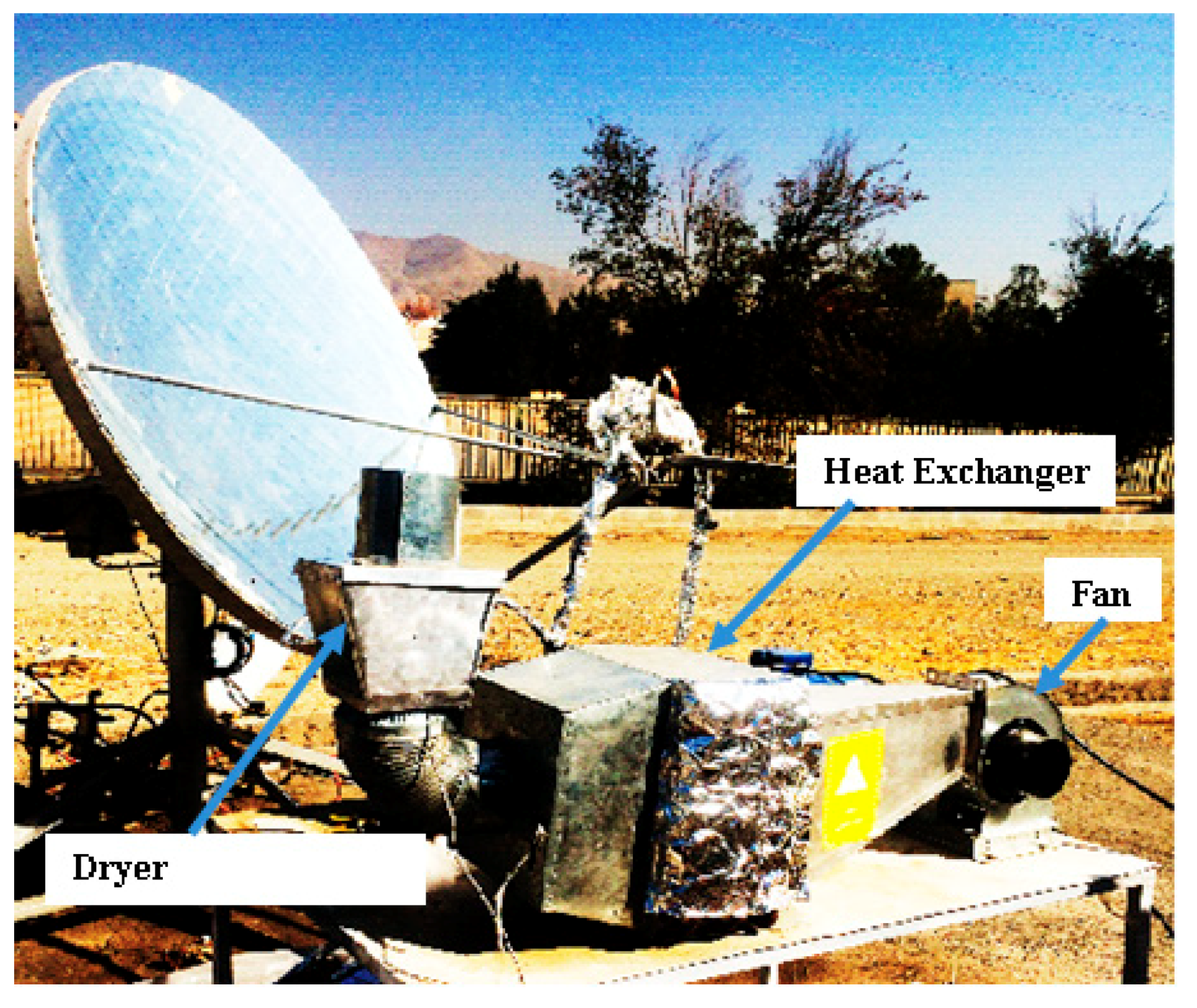
Another part of the indirect solar dryer system is the dryer system. Different parts of the solar dryer are illustrated in Figure 3. The dryer system consisted of a fan for blowing air, a heat exchanger for transferring thermal energy from the solar working fluid to air, and a dryer compartment for carrying mint. The forced convection was used to pass the hot mass of air from the heat exchanger into the drying compartment. Based on previously reported papers, it was concluded that the highest required energy for mint drying is 60 °C. The designed dryer system was assumed to be a thin-layer system with mint depth of 5 cm. The weight of the sample for each experimental test was assumed to be equal to 50 grams. Dimensions of the dryer compartment were calculated, with a length of 12 cm and a width of 12.5 cm. The total amount of used heat for drying can be calculated as follows:
E n = m ˙ × ( C p a + C p v × H a ) ( T i n T a m ) V h
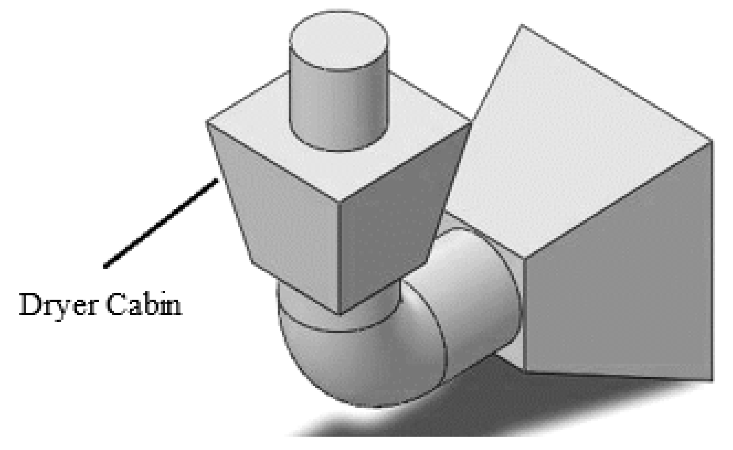
where, En (W) is required heat power for drying, m ˙ (m3/s) is volume flow rate of air at inlet, Vh (m3/kg) specific volume of air moisture, Cpa (J/kg K) is specific heat capacity of air, Cpv (J/kg K) is specific heat capacity of steam, Tin (°C) is inlet temperature, and Tam (°C) is ambient temperature. Finally, a heat exchanger was used for transferring absorbed heat by the solar working fluid to the air for drying with a cross-section of 33 × 34 cm2 and cooper tube length of 0.33 m, with the triangular arrangement. It should be stated that the drying system was simulated for investigation of the variation of air speed, and streamlines between the heat exchanger to dryer exit. This simulation was conducted by using SolidWorks 2017 and Ansys CFX 15.0 software. A view of the simulated dryer system is presented in (Figure 4)
Various operational and environmental parameters were measured during the experimental tests. The measured operational parameters were (1) solar radiation, (2) wind speed, and (3) ambient temperature. The solar radiation was measured by using Hukseflux Pyranometer, model SR12. The ambient temperature and wind speed were measured by using a PT-100 sensor and anemometer CT model, AM-4220, respectively. On the other side, the measured conditional parameters were as follows: (1) air mass flow rate; (2) inlet and outlet temperatures of the solar working fluid for the cavity receiver and heat exchanger; and (3) inlet and outlet temperatures of air at the dryer compartment. The air mass flow rate was measured by using a graduated cylinder, and the temperature of the solar working fluid and air at the dryer system were measured by using PT-100 sensors. Accuracy and ranges of the measuring instruments are explained in Table 2.

2.2. Nanofluid Preparation

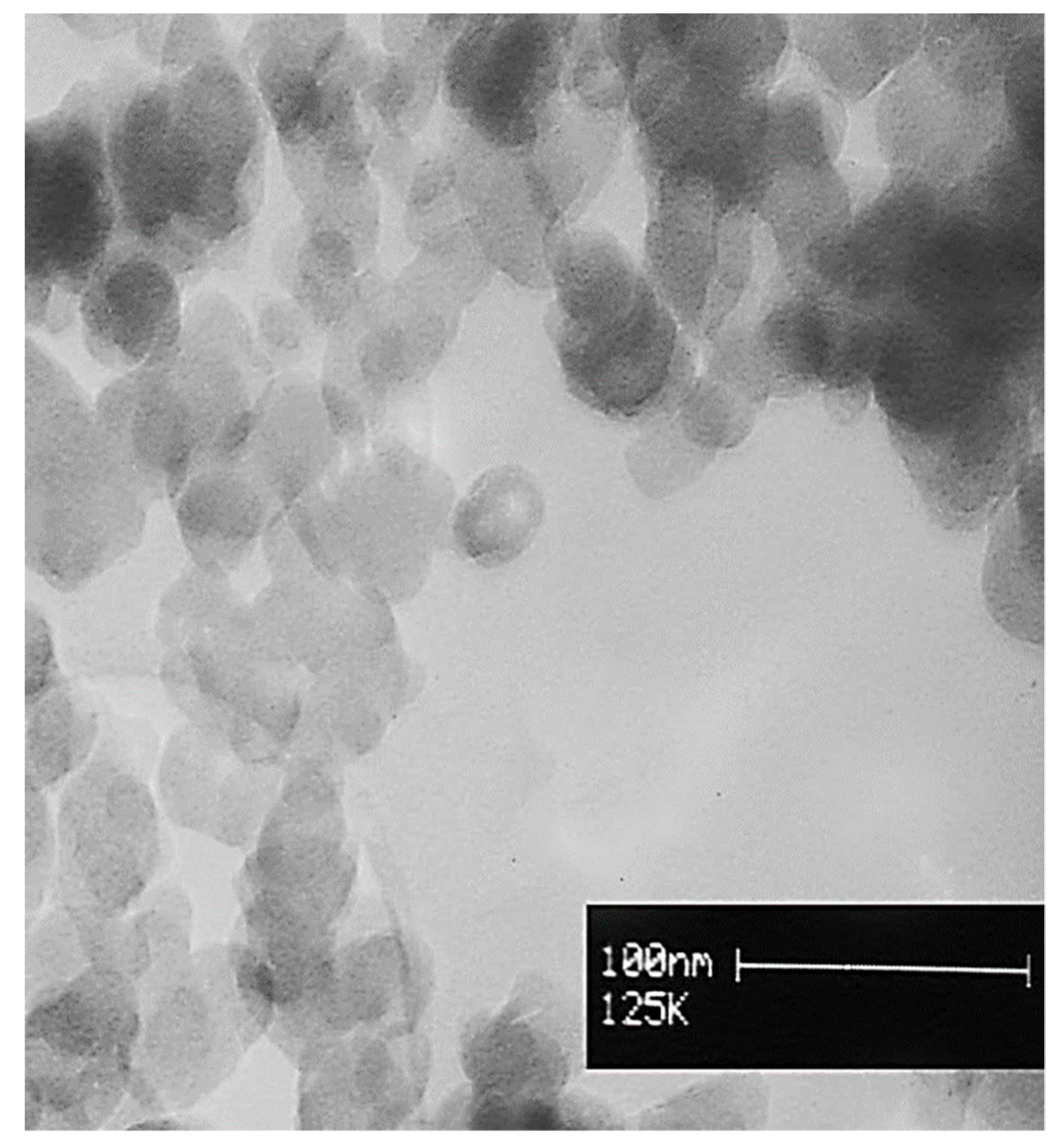
In this research, the Al2O3/thermal oil nanofluid and pure oil were used as the solar working fluid. The Alumina nanoparticles (gamma, 99%, 30–40 nm) were provided by the US Research Nanomaterial Company. A TEM picture of the alumina nanoparticles is exhibited in Figure 5. It should be mentioned that Behran thermal oil was used as the based fluid [41].
For preparing the nanofluid, firstly, the specified quantity of nanoparticles was weighted based on the 0.8% mass fraction of nanoparticles, using the following equation:
φ p = m p × 100 m p + m o i l = m p × 100 m p + ( ρ o i l V o i l )
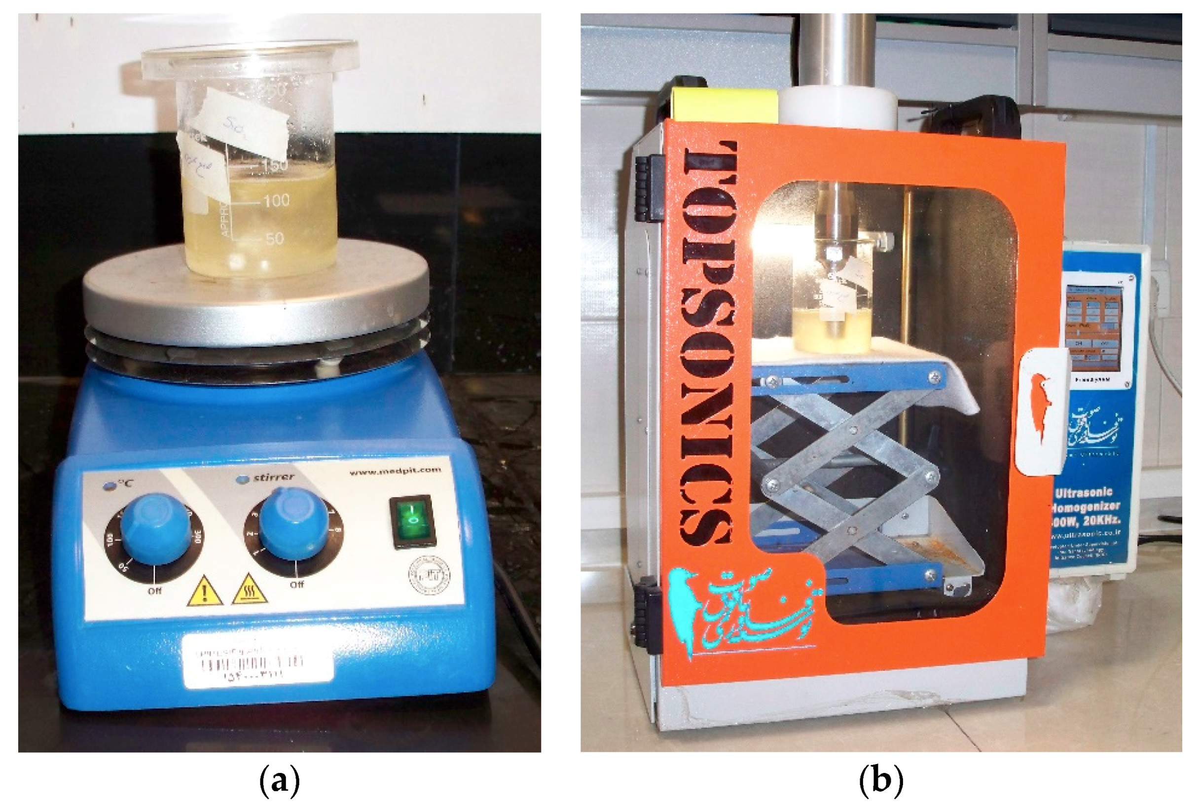
In this equation, φ p is nanofluid volume fraction, m p (kg) is the nanoparticle mass,   m o i l   (kg) is thermal oil mass, ρ o i l (kg/m3) is the density of the thermal oil, and V o i l (m3) is the volume of the thermal oil. Based on this equation, for the specified volume of the thermal oil and nanofluid mass flow rate, the quantity of nanoparticles was calculated. Afterward, the specified quantity of the nanoparticles was slowly added to the thermal oil. Then, the suspension was well stirred by a stirrer at 400 rpm and 150 °C for one hour, to separate the particle agglomerations. Finally, the prepared suspensions were inserted in an ultrasonic system for about 15 minutes, with a power level of 100 W, to break down the agglomeration between nanoparticles. A view of the preparation of the Al2O3/thermal oil nanofluid by using the stirrer device and an image of the ultrasonic system which was used from Tehran University, Tehran, Iran, are displayed in Figure 6a,b.
The thermal properties of the alumina/thermal oil nanofluid were calculated based on the reported experimental relationships by Reference [42] for the alumina/thermal oil nanofluid. The thermal conductivity, density, and heat capacity of the Al2O3/thermal oil nanofluid were calculated according to the reported equation by [42], as follows:
k n f = 1.4408 0.829 ( l n   T ) + 0.1588 ( ln T ) 2 0.0702 ( 1 φ P ) 0.2151 ( ln T ) ( 1 φ P ) + 0.5965 T ( 1 φ P )   0.39 T ( 1 φ P ) 2
ρ n f = 1012.83 762.91 T 0.7125 + 1578.311 ( 1 φ P ) 0.4211 + 671.4463 ( 1 φ P ) 3.2992 T 0.1938
C p , n f = 1.2674 + [ 0.0026 0.1467 ( 1 φ P ) 150 0.0414 T 0.602 ] 2
In these equations, k n f (W/m K) is the nanofluid heat conductivity, ρ n f (kg/m3) is the nanofluid density, C p , n f ( J / kg   K ) is the nanofluid heat capacity, T (°C) is the nanofluid temperature, and φ P is the nanoparticle volume fraction.
At the end of this subsection, it has to be said that the selected nanofluid is a typical one, according to the existing literature. Al2O3 is a usual nanoparticle which has been used in numerous cases. The selected concentration is 0.8%, which is enough for having performance enhancement, but not so high as to have agglomeration issues and a high cost. The nanoparticle diameters are about 30–40 nm, which are typical values. Generally, it has to be said that higher nanoparticle concentration and lower nanoparticle diameters usually lead to higher thermal performance and to higher pressure drop.

2.3. Solar Collector Performance Evaluation

In the first stage of the study, the thermal performance of the solar system was calculated based on the following equations. Firstly, the thermal efficiency is defined as the ratio of the useful heat to the solar irradiation on the collector aperture in the Equation (6). The useful heat production is calculated as the energy balance in the fluid volume, as Equation (7) indicates. Lastly, Equation (8) shows the calculation of the solar energy on the collector [43].
η t h = Q ˙ n e t Q ˙ s o l a r
Q ˙ n e t = m ˙ n f C p , n f ( T o u t T i n )
Q ˙ s o l a r = I b e a m π D c o n c 2 4
In these equations, η t h is the thermal efficiency, Q ˙ n e t   (W) is the heat gain by the cavity receiver, Q ˙ s o l a r (W) is defined as the input solar radiation, m ˙ n f (kg/s) is the working fluid mass flow rate, C p n f   (J/kg K) is the working fluid heat capacity, I b e a m   (W/m2) is the solar radiation, D c o n c (m) is the aperture diameter of the dish concentrator, and T o u t   a n d   T i n (K) are the outlet and inlet temperatures of the working fluid, respectively.

2.4. Dryer Performance Evaluation

As mentioned in the previous sections, mint plant was selected for drying in this research. For each test, 50 gr of mint was provided from a farm near the laboratory position. The prepared samples were located in a refrigerator, at a temperature of 4 °C. During the experimental tests, initial moisture content was estimated based on the ASABE S358.2 (2010) method. Based on this method, 100 gr of mint was placed in an oven for 24 h, at 100 °C. Reducing the moisture content was recorded by measuring the weight of the samples during the drying process by weighing the sample with an electronic balance with a capacity of 1 kg and resolution of ±0.01 gr. The moisture content was calculated on wet bases as follows:
M t = ( w w w d w w ) × 100
where, M t is moisture content on wet bases, w w (gr) is the weight of the wet sample, w d (gr) is the weight of the dry sample. Experiments were conducted at three levels of inlet air temperature, 40, 50, and 60 °C, as well as three levels of inlet air speed, 0.5, 1, and 1.5 m/s. All of the tests were done based on three repeats. Consequently, 27 tests were predicted for the investigation of all of the parameters, based on three repeats. It should be mentioned that Al2O3/oil nanofluid was used as the solar working fluid for all of the tests in this section. Temperature and speed of air were adjusted by using variation of air speed with an inventor system, and variation of the nanofluid as solar working fluid with a flow meter. It should be stated that drying processes were conducted at the steady-state condition.

2.5. Color Variation of Mint Leaves

The performance of the solar dryer system was investigated by recording figures of color variation of the mint leaves during the experimental tests. Visional tests are accounted as conventional methods for evaluating the quality of agriculture processes such as drying. Consequently, RGB method was used based on red, green, and blue content of each pixel in the range of 0–255. It should be mentioned that pictures of samples were taken with a camera (FinePix sl1000), with a resolution of 921,000. A view of the color variation test of mint leaves is presented in Figure 7.
Color index and color variation average were calculated as follows:
Δ R = R 1 R 2 R 1 × 100
Δ G = G 1 G 2 G 1 × 100
Δ B = B 1 B 2 B 1 × 100
Δ L = Δ R + Δ G + Δ B 3
where, R1, G1, and B1 are amounts of red, green, and blue content of samples before the drying process, and R2, G2, and B2 are amounts of red, green, and blue content of samples after the drying process, respectively. Also, Δ R , Δ G , and Δ B are amounts of variation percentage of red, green, and blue, respectively. Finally, Δ L is presented as the average amount of RGB variation. These analyses were conducted by using MATLAB software.

3. Result and Discussion

3.1. Solar Dish Performance

In this section, experimental results of the cavity thermal performance using pure thermal oil and Al2O3/thermal oil nanofluid as the solar working fluid are reported. Variations of measured environmental and conditional parameters were presented during the experimental tests. The experimental tests were carried out from 9:00 to 14:00 on 29 and 30 September 2017. The volume flow rate of the solar working fluids was 15 mL/s during the experimental tests. The results of experimental tests using pure thermal oil and Al2O3/thermal oil nanofluid are separately presented in Section 3.1.1 and Section 3.1.2, respectively. Finally, a comparison study related to the cavity thermal performance using pure thermal oil and Al2O3/thermal oil nanofluid is presented in Section 3.1.3.

3.1.1. Pure Thermal Oil

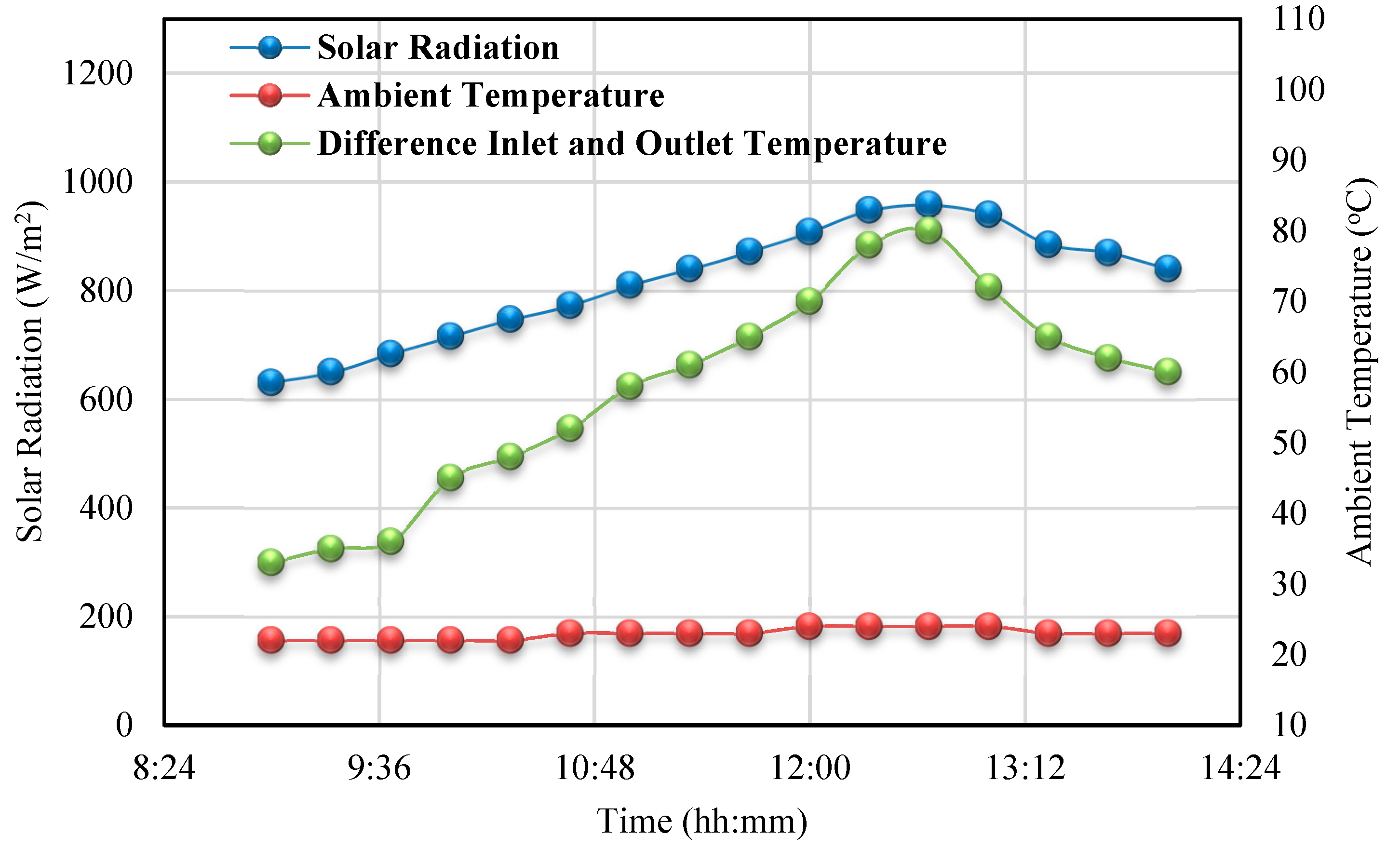
In this section, the thermal performance of the dish concentrator with the cylindrical cavity receiver using pure thermal oil as the solar working fluid is reported. The experimental test was conducted from 9:00 to 14:00 on 29 September 2017. Figure 8 presents the variation of solar radiation, ambient temperature, and oil temperature difference at the inlet and outlet of the cavity receiver during the experimental day. As seen in Figure 8, the solar radiation changed in the range of 958 W/m2 at 12:40 to 631 W/m2 at 9:00. In addition, the ambient temperature varied from 24 °C at 12:40 to 22 °C at 9:00. As seen in Figure 8, the oil difference temperature at the inlet and outlet of the cavity receiver changed from 80 °C at 12:40 to 33 °C at 9:00. It could be seen that the oil difference temperature at inlet and outlet of the cavity receiver has a similar trend data compared to the variation of the solar radiation during the experimental test.
Variation of cavity top wall temperature, cavity sidewall temperature, and wind speed during the experimental test using the thermal oil as the solar working fluid is depicted in Figure 3. The cavity top wall temperature varied in the range of 235 °C at 12:40 to 186 °C at 9:00. Additionally, the variation of the measured cavity sidewall temperature was reported from 185 °C at 12:40 to 136 °C at 9:00 during the experimental test of the cylindrical cavity receiver with the pure thermal oil as the solar working fluid. It can be seen that the cavity top wall had resulted in higher surface temperature compared to the cavity sidewall. This is a reasonable result because there is a high number of solar rays that are concentrated in the top wall, and so the temperature is increased in this region. Also, it could be seen that the wind speed varied from 2 m/s at 12:00 to zero at 9:00 during the experimental test. As shown in Figure 9, the cavity surface temperatures resulted in a comparable trend with the variation of the wind speed.
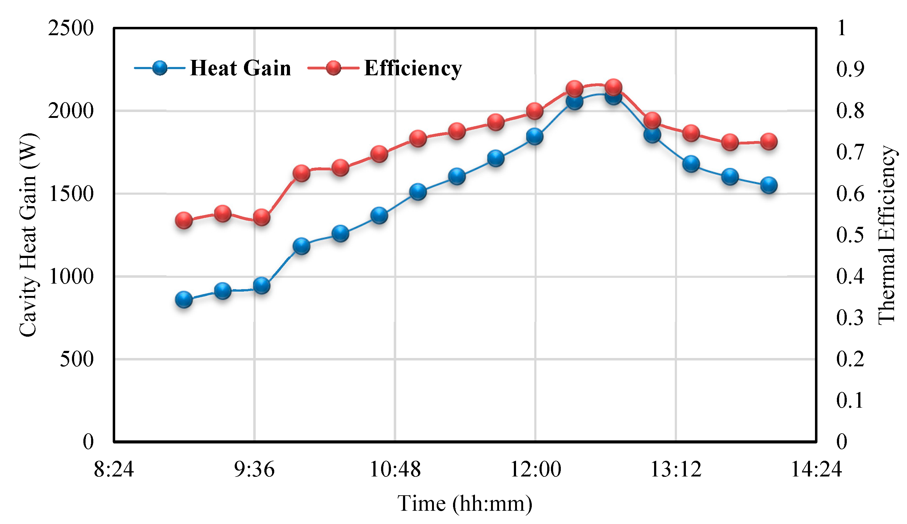
Finally, a variation of cavity heat gain and thermal efficiency of the solar dish concentrator with the cylindrical cavity receiver using thermal oil as the solar working fluid during the experimental test on 29 September 2017 is presented in Figure 10. The cavity heat gains varied from 2086 W at 12:40 to 858 W at 9:00. It could be seen that the thermal efficiency of the solar system changed in the range of 85% from 12:40 to 53% at 9:00. As concluded from Figure 10, the cavity heat gain and thermal efficiency of the cavity receiver show similar trend data compared to the oil temperature difference at the inlet and outlet of the cavity receiver. It can be concluded that the oil temperature difference at the inlet and outlet of the cavity receiver is accounted as an effective parameter related to the thermal performance of the dish concentrator system with the cavity receiver. Lastly, it has to be commented that, during the first operating hour in the morning, the system efficiency was relatively low because there were no steady-state conditions and the system needed time to warm up.

3.1.2. Al2O3/Thermal Oil Nanofluid

Results of the experimental test related to the thermal performance of the dish concentrator with the cylindrical cavity receiver were presented by using Al2O3/thermal oil nanofluid as the solar working fluid. The experimental test was conducted from 9:00 to 14:00 on 30 September 2017. The variation of solar radiation, ambient temperature, and oil temperature difference at the inlet and outlet of the cavity receiver during the experimental day are shown in Figure 11. The solar radiation varied in the range of 964 W/m2 at 12:40 to 635 W/m2 at 9:00. Additionally, the ambient temperature varied from 24 °C at 12:40 to 21 °C at 9:00. Figure 11 depicts that the oil difference temperature at the inlet and outlet of the cavity receiver varied from 92 °C at 12:40 to 35 °C at 9:00. Similar to the concluded results by the previous section, the oil difference temperature at the inlet and outlet of the cavity receiver showed a similar trend compared to the variation of the solar radiation during the experimental test.
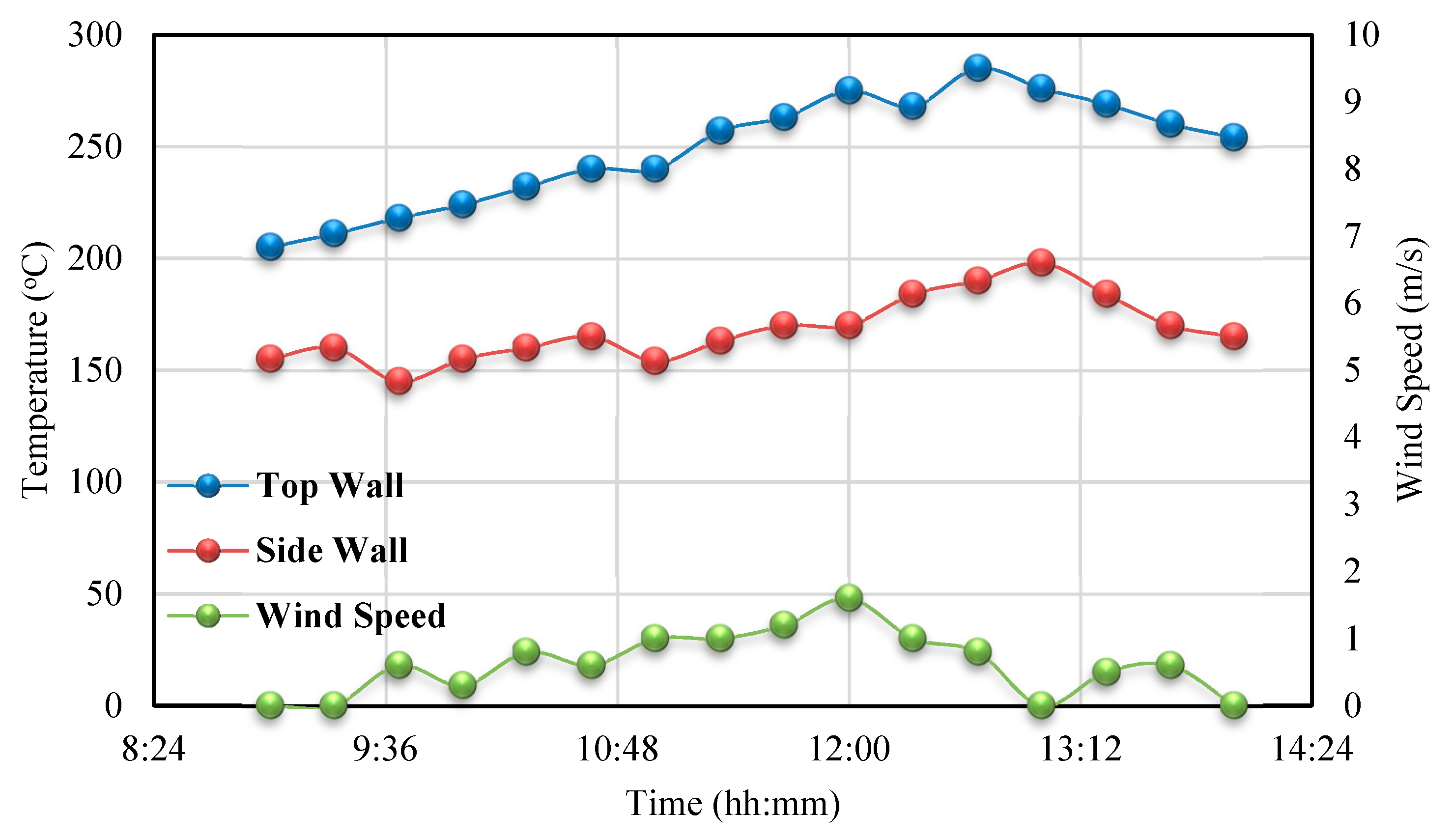
Figure 12 presents the variation of the cavity top wall temperature, cavity sidewall temperature, and wind speed during the experimental test of the cylindrical cavity receiver using the Al2O3/thermal oil nanofluid as the solar working fluid. As seen in Figure 12. , the cavity top wall temperature changed in the range of 285 °C at 12:40 to 205 °C at 9:00. Also, the measured cavity sidewall temperature varied from 198 °C at 13:00 to 145 °C at 9:40. As a result, the cavity top wall temperature showed higher amounts compared to the cavity sidewall temperature. It has to be said that the sidewall temperature has a smaller deviation during the day compared to the top wall temperature deviation. Moreover, wind speed varied from 1.6 m/s to zero.
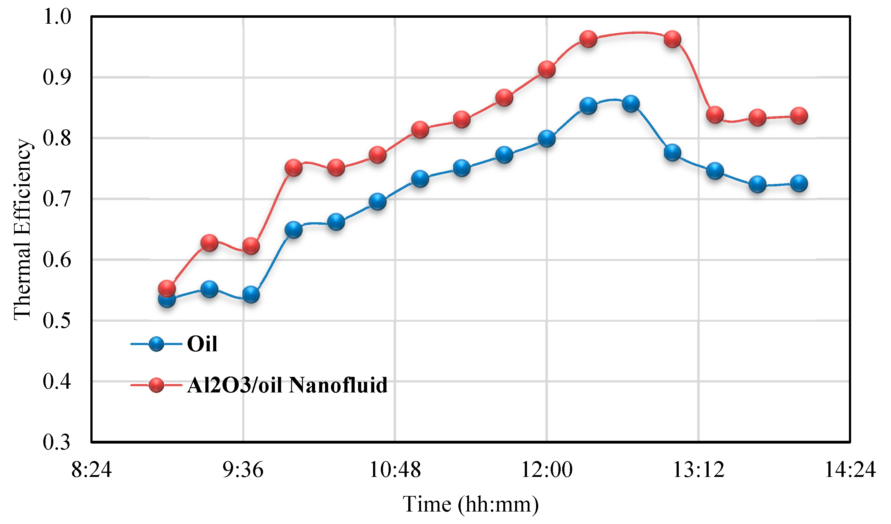
Figure 13 displays variation of cavity heat gain, and thermal efficiency of the solar dish concentrator using Al2O3/thermal oil nanofluid as the solar working fluid on 30 September 2017. It can be seen that the cavity heat gain changed in the range of 2333 W at 12:20 to 891 W at 9:00. The thermal efficiency of the solar system changed in the range of 96% from 12:20 to 55% at 9:00. As stated in the previous section, it could result that the cavity heat gain and thermal efficiency of the cavity receiver have similar trend data compared to the oil temperature difference at the inlet and outlet of the cavity receiver and the oil. Temperature difference at the inlet and outlet of the cavity receiver can be accounted for as an effective parameter related to the thermal performance of the dish concentrator system with the cylindrical cavity receiver.

3.1.3. Comparison of Performance

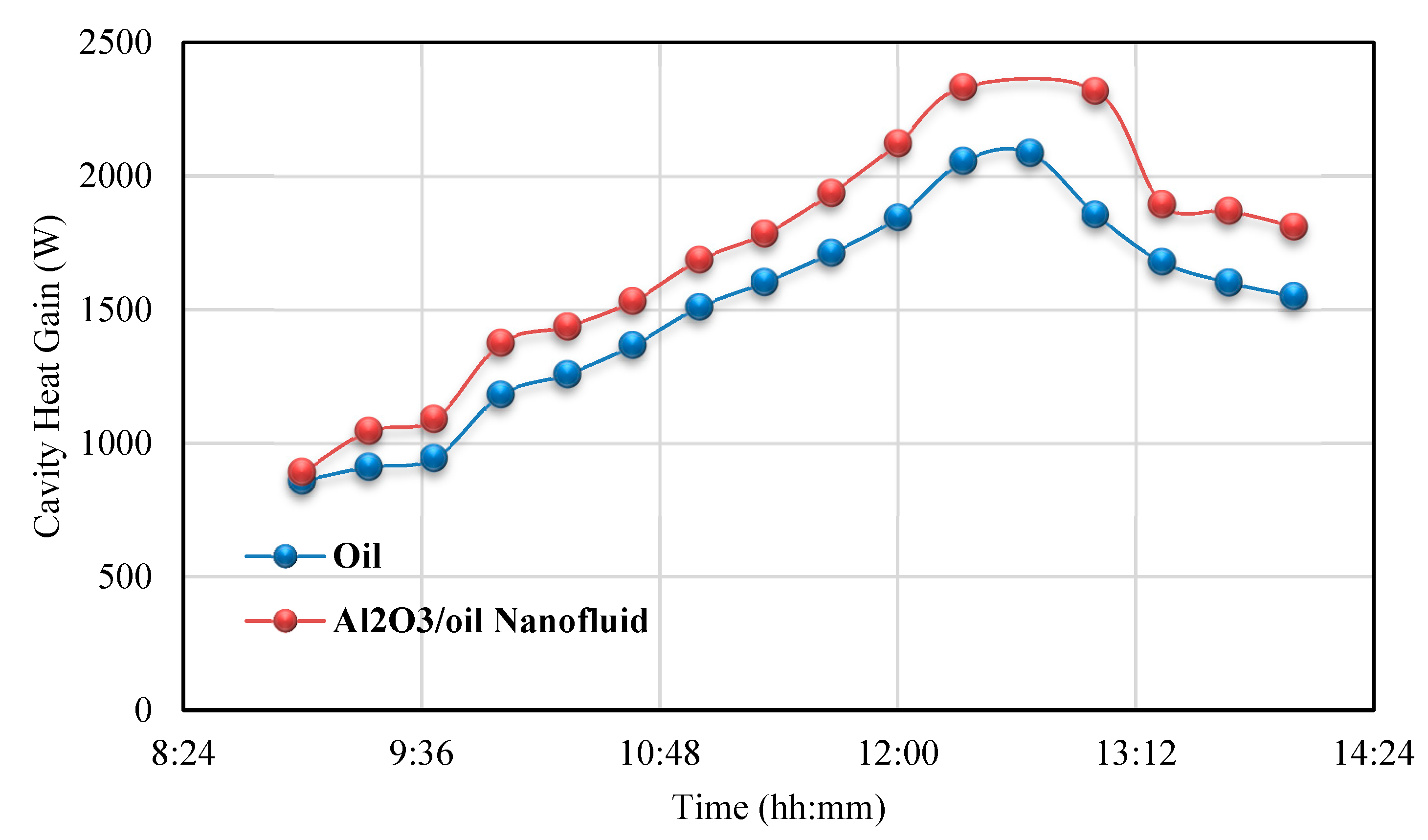
In this section, a comparison study on the thermal performance of the dish concentrator using the pure thermal oil and the Al2O3/thermal oil nanofluid is presented. Figure 14 and Figure 15 show a comparison of the cavity heat gain and thermal efficiency of the dish concentrator using the cylindrical cavity receiver with the pure thermal oil and Al2O3/thermal oil nanofluid as the solar working fluid during experimental tests, respectively. It should be mentioned that the environmental conditions have nearly the same amounts on two experimental days with the pure thermal oil and the nanofluid as presented in the previous sections. In conclusion, the measured results of two experimental days could be compared together. As seen from Figure 14 and Figure 15, the thermal performance of the solar system, including the cavity heat gain and thermal efficiency, improved by using application of the nanofluid as the solar working fluid. This issue is due to the better thermal properties of the nanofluids compared to the based fluid, as seen in this research. More specifically, the nanofluid present higher thermal conductivity, which increases the heat-transfer rates inside the flow, something that enhances the system's thermal efficiency.

3.2. Solar Dryer Performance

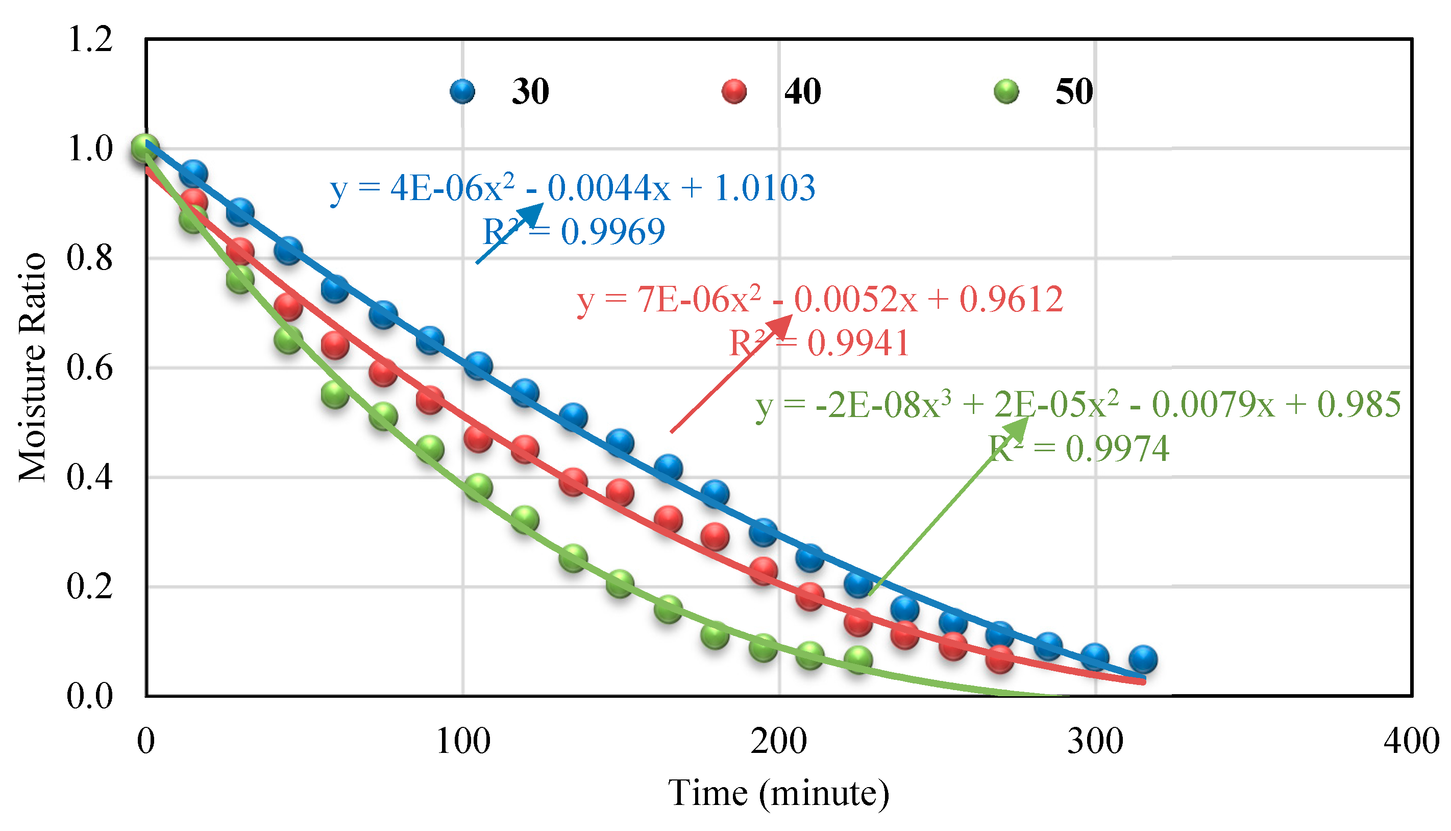
As concluded from the previous section, the Al2O3/thermal oil nanofluid resulted in higher thermal performance compared to the pure oil as the solar working fluid. In this section, the performance of the solar dryer system with the Al2O3/thermal oil nanofluid as the solar working fluid of the cylindrical cavity receiver is reported. The nanofluid was tested at a mass fraction of 0.8%. The drying system was examined at three levels of the air speed as 0.5, 1, and 1.5 m/s. In addition, the solar dryer system was tested at three levels of drying temperature: 30, 40, and 50 °C. Variations of mint drying time at different air speeds and drying temperatures are depicted in Figure 16, Figure 17 and Figure 18. As seen from Figure 16, Figure 17 and Figure 18, the mint drying time was decreased by increasing drying temperature and increasing air speed. The highest drying time was measured equal to 320 min for the condition of the air speed equal to 0.5 m/s and the drying temperature of 30 °C, whereas the lowest drying time was measured for the condition of the air speed equal to 1.5 m/s and the drying temperature of 50 °C. As seen, the drying time increased with spending the time of the experimental test. This issue was due to the evaporation of the surface moisture at the start of the drying process; consequently, the process of drying was quickly conducted. After spending time, the content of the surface moisture finished, and internal moisture had to be transferred to the mine surface and evaporated. This process took more time compared to the evaporation of surface moisture. Some experimental relationships for prediction of moisture ratio of the mint versus spending time of experimental tests are suggested in Table 3 for different amounts of the air speed and drying temperature. These suggested experimental relationships could be used for the prediction of the moisture ratio of the mint with spending the time of the experimental tests.
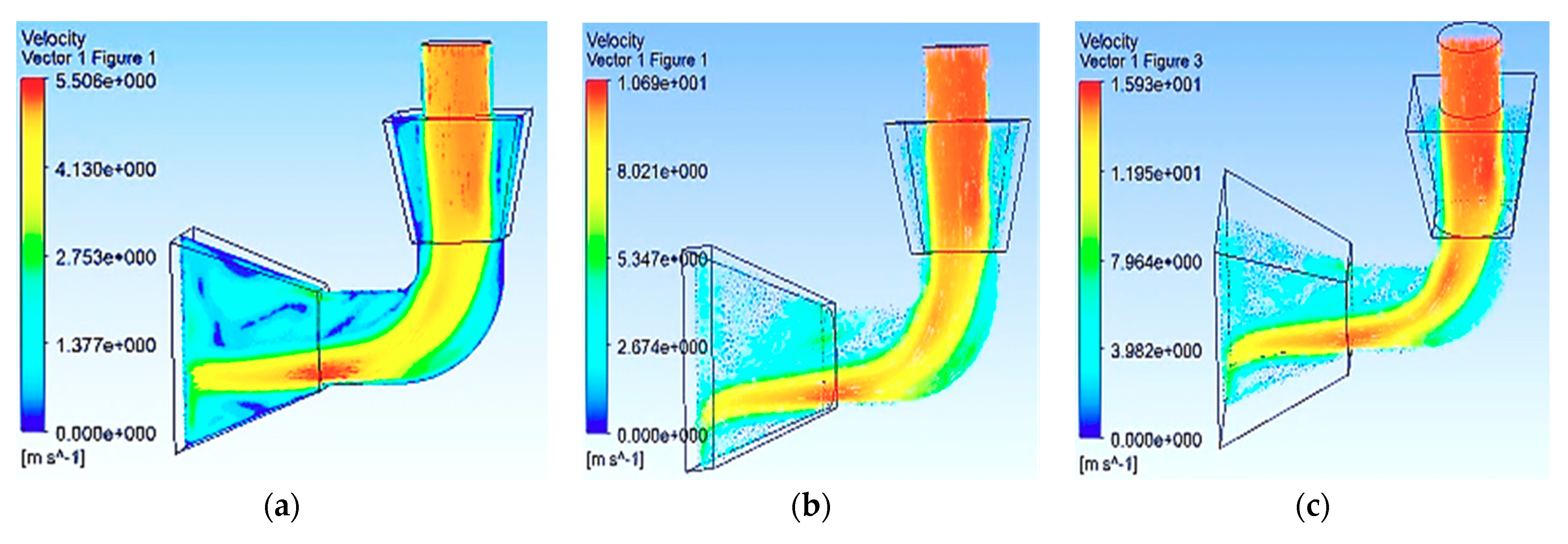
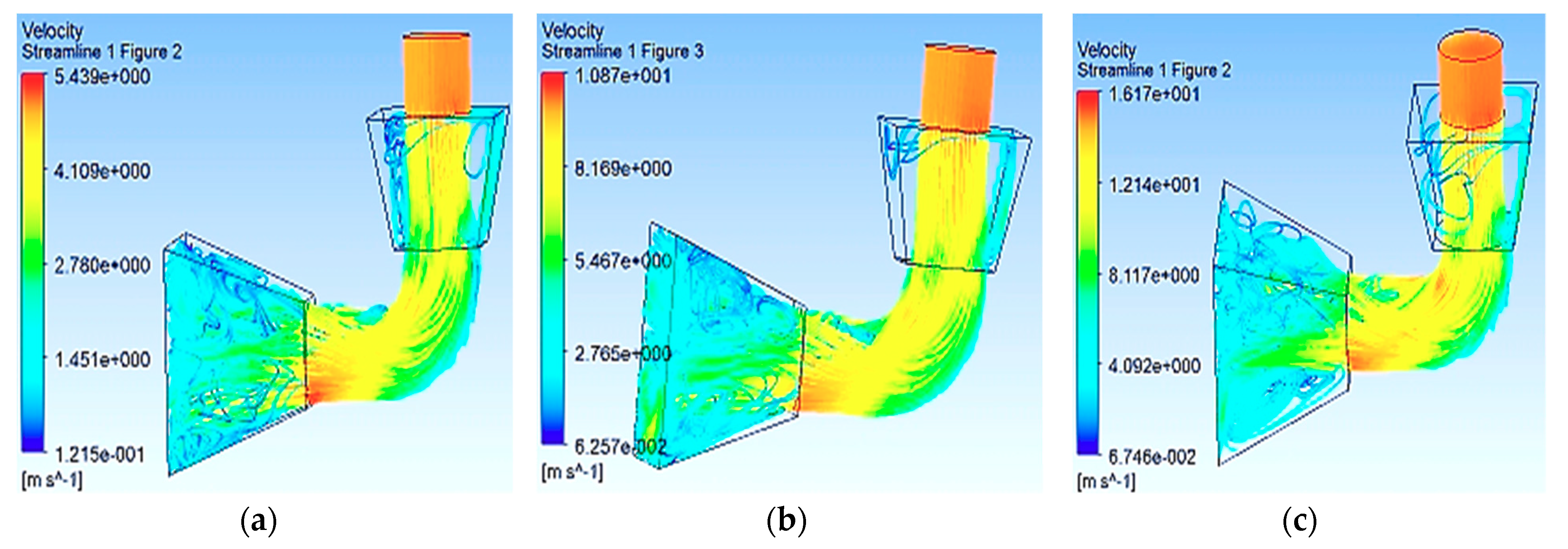
Concluded simulation results of the solar dryer using the SolidWorks and ANSYS CFX software are presented in this part. Figure 19. depicts the variation of air speed in the dryer at different air inlet speeds: 0.5, 1, and 1.5 m/s. It should be mentioned that these analyses were conducted for an air inlet temperature of 30 °C. As seen in Figure 19, air outlet speed increased with increasing air inlet speed from maximum 5.5 to 1.6 m/s, with air inlet speed from 0.5 to 1.5 m/s, respectively. Variation of air speed resulted in more uniform distribution at outlet of the dryer with increasing air inlet speed. Also, the variation of the streamlines at different air inlet speeds, 0.5, 1, and 1.5 m/s, are displayed in Figure 20. Similar results compared to Figure 19 can be concluded for variation of the streamlines at different air inlet speeds. Finally, the calculated results by the SolidWorks and ANSYS CFX software were validated based on the measured data during the experimental tests. A comparison between numerical and experimental results of the current research is presented in Figure 21. As seen, good agreement was observed between the calculated numerical results and measured experimental data. More developed numerical results will be presented in the next studies by the authors.
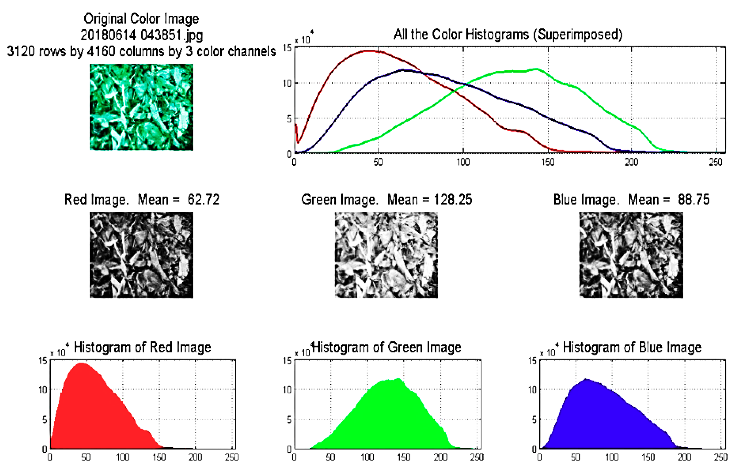
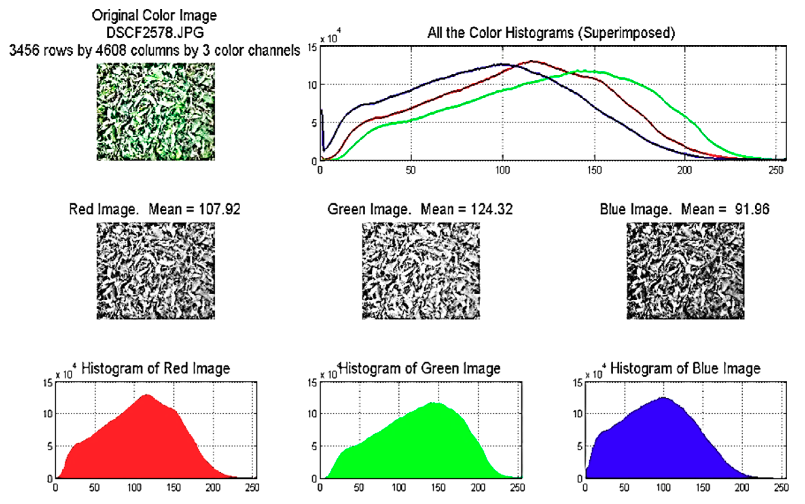
In this part, some results of the color histogram of the wet and dried mint samples based on the RGB method are presented. The color histograms of three samples, the wet mint, dried mint at air inlet speed of 1 m/s and inlet temperature of 40 °C, and dried mint at air inlet speed of 1 m/s and inlet temperature of 50 °C, are presented Figure 22, Figure 23 and Figure 24, respectively. As seen, the intensity amount of the red color of the mint increased with the drying process compared to the intensity amount of the red color of the wet mint sample. It can be concluded that the intensity of red color increased from 102.13 to 107.92 with increasing inlet temperature from 40 to 50 °C, respectively. On the other side, intensity of green color decreased with increasing inlet temperature from 117.88 to 124.32 for inlet temperature from 40 to 50 °C, respectively. In addition, the intensity of the blue color increased with increasing from 89.05 to 91.96 for inlet temperature from 40 to 50 °C, respectively. Finally, it can be understood that higher inlet temperature resulted in higher red color intensity, lower green color intensity, and higher blue color intensity.

4. Conclusions

In this research, a solar dryer system using a solar dish concentrator was experimentally investigated for drying mint. A cylindrical cavity receiver was used as the dish absorber. The thermal performance of the solar system was tested by using Al2O3/oil nanofluid and pure oil as the solar working fluid. The performance of the solar drying system using the Al2O3/oil nanofluid was considered based on the experimental tests. In addition, the solar dryer system was simulated by the SolidWorks and ANSYS CFX software. On the other side, the color histogram of the wet and dried mint samples based on the RGB method was considered. The main results of this study could be summarized as the follows:
  • The difference in temperature of the solar working fluids at the inlet and outlet of the cavity receiver showed similar trend data compared to the variation of the solar radiation during the experimental test.
  • The cavity top wall resulted in a higher surface temperature compared to the cavity sidewall. Also, the cavity surface temperatures resulted in comparable trend data compared to the variation of the wind speed during the experimental tests. The higher temperature of the top wall is justified by the high number of solar rays that reach this region.
  • The maximum thermal efficiency of the solar system using the pure oil and the Al2O3/oil nanofluid was measured equal to 85% and 96%, respectively. Generally, the cavity heat gain and thermal efficiency of the solar system improved by using the application of the nanofluid as the solar working fluid. Practically, the use of nanofluids leads to higher heat-transfer rates, which aid the working fluid to gain more useful heat, and so the thermal losses are reduced due to the lower wall-temperature levels.
  • The required time for mint drying decreased by increasing drying temperature and increasing air speed. This is a reasonable result because, in these operating conditions, there are higher heat-transfer rates. The highest drying time was measured equal to 320 min for the condition of the air speed equal to 0.5 m/s, and the drying temperature of 30 °C, whereas the lowest drying time was measured for the condition of the air speed equal to 1.5 m/s, and the drying temperature of 50 °C. The drying time had increased with spending the time of the experimental test.
  • It was concluded that air outlet speed increased with increasing air inlet speed. Also, variation of air speed had resulted in more uniform distribution at the outlet of the dryer, with increasing air inlet speed. Based on a comparison between numerical and experimental results of the current research, good agreement was observed between the calculated numerical results and measured experimental data.
  • Finally, based on the color histogram of the wet and dried mint samples, it was concluded that the intensity amount of the red color of the mint increased with the drying process compared to the intensity amount of the red color of the wet mint sample. Also, the red color intensity amount of dried mint samples increased with increasing inlet air temperature.

Author Contributions

Conceptualization, A.H.A. and R.L.; methodology, A.H.A; formal analysis, A.H.A., G.N., S.G., T.Y. and E.B.; writing—original draft preparation, A.H.A., G.N., S.G., T.Y., E.B. and R.L.; writing—review and editing, A.H.A., R.L., G.N. and S.G.

Funding

The authors are grateful to the Tarbiat Modares University (http://www.modares.ac.ir) for financial support given under IG/39705 grant for renewable Energies of Modares research group.

Acknowledgments

We thank our colleagues from TMU Renewable Energies Research Institute who provided insight and expertise that greatly assisted this research.

Conflicts of Interest

The authors declare no conflicts of interest.

References

  1. Ghobadian, B.; Najafi, G.; Rahimi, H.; Yusaf, T. Future of renewable energies in Iran. Renew. Sustain. Energy Rev. 2009, 13, 689–695. [Google Scholar] [CrossRef]
  2. Khoobbakht, G.; Najafi, G.; Karimi, M.; Akram, A. Optimization of operating factors and blended levels of diesel, biodiesel and ethanol fuels to minimize exhaust emissions of diesel engine using response surface methodology. Appl. Therm. Eng. 2016, 99, 1006–1017. [Google Scholar] [CrossRef]
  3. Najafi, G.; Ghobadian, B.; Yusaf, T.; Ardebili, S.M.; Mamat, R. Optimization of performance and exhaust emission parameters of a SI (spark ignition) engine with gasoline–ethanol blended fuels using response surface methodology. Energy 2015, 90, 1815–1829. [Google Scholar] [CrossRef]
  4. Yusaf, T.; Hamawand, I.; Baker, P.; Najafi, G. The effect of methanol-diesel blended ratio on CI engine performance. Int. J. Automot. Mech. Eng. 2013, 8, 1385–1395. [Google Scholar] [CrossRef]
  5. Kartite, J.; Cherkaoui, M. Study of the different structures of hybrid systems in renewable energies: A review. Energy Procedia 2019, 157, 323–330. [Google Scholar] [CrossRef]
  6. Phillips, L. Solar Energy, in Managing Global Warming: An Interface of Technology and Human Issues; Letcher, T.M., Ed.; Elsevier: Amsterdam, The Netherlands, 2018; pp. 317–332. [Google Scholar]
  7. Kalogirou, S.A. Solar thermal collectors and applications. Prog. Energy Combust. Sci. 2004, 30, 231–295. [Google Scholar] [CrossRef]
  8. Eltawil, M.A.; Azam, M.M.; Alghannam, A.O. Energy analysis of hybrid solar tunnel dryer with PV system and solar collector for drying mint (MenthaViridis). J. Clean. Prod. 2018, 181, 352–364. [Google Scholar] [CrossRef]
  9. Qin, J.; Hu, E.; Nathan, G.J.; Chen, L. Concentrating or non-concentrating solar collectors for solar Aided Power Generation? Energy Convers. Manag. 2017, 152, 281–290. [Google Scholar] [CrossRef]
  10. Bellos, E.; Tzivanidis, C. Alternative designs of parabolic trough solar collectors. Prog. Energy Combust. Sci. 2019, 71, 81–117. [Google Scholar] [CrossRef]
  11. Le Roux, W.G.; Bello-Ochende, T.; Meyer, J.P. The efficiency of an open-cavity tubular solar receiver for a small-scale solar thermal Brayton cycle. Energy Convers. Manag. 2014, 84, 457–470. [Google Scholar] [CrossRef] [Green Version]
  12. Loni, R.; Kasaeian, A.; Asli-Ardeh, E.A.; Ghobadian, B. Optimizing the efficiency of a solar receiver with tubular cylindrical cavity for a solar-powered organic Rankine cycle. Energy 2016, 112, 1259–1272. [Google Scholar] [CrossRef]
  13. Loni, R.; Kasaeian, A.; Shahverdi, K.; Asli-Ardeh, E.A.; Ghobadian, B.; Ahmadi, M.H. ANN model to predict the performance of parabolic dish collector with tubular cavity receiver. Mech. Ind. 2017, 18, 408. [Google Scholar] [CrossRef]
  14. Loni, R.; Kasaeian, A.; Mahian, O.; Sahin, A. Thermodynamic analysis of an organic rankine cycle using a tubular solar cavity receiver. Energy Convers. Manag. 2016, 127, 494–503. [Google Scholar] [CrossRef]
  15. Pavlovic, S.; Loni, R.; Bellos, E.; Vasiljević, D.; Najafi, G.; Kasaeian, A. Comparative study of spiral and conical cavity receivers for a solar dish collector. Energy Convers. Manag. 2018, 178, 111–122. [Google Scholar] [CrossRef]
  16. Loni, R.; Asli-Ardeh, E.A.; Ghobadian, B.; Bellos, E.; Le Roux, W.G. Numerical comparison of a solar dish concentrator with different cavity receivers and working fluids. J. Clean. Prod. 2018, 198, 1013–1030. [Google Scholar] [CrossRef]
  17. Venkatachalam, T.; Cheralathan, M. Effect of aspect ratio on thermal performance of cavity receiver for solar parabolic dish concentrator: An experimental study. Renew. Energy 2019, 139, 573–581. [Google Scholar] [CrossRef]
  18. Yan, J.; Peng, Y.-D.; Cheng, Z.-R. Optimization of a discrete dish concentrator for uniform flux distribution on the cavity receiver of solar concentrator system. Renew. Energy 2018, 129, 431–445. [Google Scholar] [CrossRef]
  19. Yang, S.; Wang, J.; Lund, P.D.; Jiang, C.; Huang, B. Design and performance evaluation of a high-temperature cavity receiver for a 2-stage dish concentrator. Sol. Energy 2018, 174, 1126–1132. [Google Scholar] [CrossRef]
  20. Loni, R.; Kasaeian, A.; Asli-Ardeh, E.A.; Ghobadian, B.; Le Roux, W. Performance study of a solar-assisted organic Rankine cycle using a dish-mounted rectangular-cavity tubular solar receiver. Appl. Therm. Eng. 2016, 108, 1298–1309. [Google Scholar] [CrossRef]
  21. Karimi, R.; Gheinani, T.T.; Avargani, V.M. A detailed mathematical model for thermal performance analysis of a cylindrical cavity receiver in a solar parabolic dish collector system. Renew. Energy 2018, 125, 768–782. [Google Scholar] [CrossRef]
  22. Pavlovic, S.; Bellos, E.; Loni, R. Exergetic investigation of a solar dish collector with smooth and corrugated spiral absorber operating with various nanofluids. J. Clean. Prod. 2018, 174, 1147–1160. [Google Scholar] [CrossRef]
  23. Hamzah, M.H.; Sidik, N.A.; Ken, T.L.; Mamat, R.; Najafi, G. Factors affecting the performance of hybrid nanofluids: A comprehensive review. Int. J. Heat Mass Transf. 2017, 115, 630–646. [Google Scholar] [CrossRef]
  24. Abdolbaqi, M.K.; Sidik, N.A.; Aziz, A.; Mamat, R.; Azmi, W.H.; Yazid, M.N.; Najafi, G. An experimental determination of thermal conductivity and viscosity of BioGlycol/water based TiO2 nanofluids. Int. Commun. Heat Mass Transf. 2016, 77, 22–32. [Google Scholar] [CrossRef] [Green Version]
  25. Najafi, G. Diesel engine combustion characteristics using nano-particles in biodiesel-diesel blends. Fuel 2018, 212, 668–678. [Google Scholar] [CrossRef]
  26. Xuan, Y.; Li, Q. Heat transfer enhancement of nanofluids. Int. J. Heat Fluid Flow 2000, 21, 58–64. [Google Scholar] [CrossRef]
  27. Hamid, K.A.; Azmi, W.H.; Mamat, R.; Usri, N.A.; Najafi, G. Effect of temperature on heat transfer coefficient of titanium dioxide in ethylene glycol-based nanofluid. J. Mech. Eng. Sci. (JMES) 2015, 8, 1367–1375. [Google Scholar] [CrossRef]
  28. Verma, S.K.; Tiwari, A.K. Progress of nanofluid application in solar collectors: A review. Energy Convers. Manag. 2015, 100, 324–346. [Google Scholar] [CrossRef]
  29. Mahbubul, I.; Khan, M.M.A.; Ibrahim, N.I.; Ali, H.M.; Al-Sulaiman, F.A.; Saidur, R. Carbon nanotube nanofluid in enhancing the efficiency of evacuated tube solar collector. Renew. Energy 2018, 121, 36–44. [Google Scholar] [CrossRef]
  30. Loni, R.; Asli-Ardeh, E.A.; Ghobadian, B.; Najafi, G.; Bellos, E. Effects of size and volume fraction of alumina nanoparticles on the performance of a solar organic Rankine cycle. Energy Convers. Manag. 2019, 182, 398–411. [Google Scholar] [CrossRef]
  31. Loni, R.; Asli-Ardeh, E.A.; Ghobadian, B.; Kasaeian, A.; Bellos, E. Thermal performance comparison between Al2O3/oil and SiO2/oil nanofluids in cylindrical cavity receiver based on experimental Study. Renew. Energy 2018, 129, 652–665. [Google Scholar] [CrossRef]
  32. Loni, R.; Asli-Ardeh, E.A.; Ghobadian, B.; Kasaeian, A.; Bellos, E. Energy and exergy investigation of alumina/oil and silica/oil nanofluids in hemispherical cavity receiver: Experimental Study. Energy 2018, 164, 275–287. [Google Scholar] [CrossRef]
  33. Hajar, E.; Rachid, T.; Najib, B.M. Conception of a Solar Air Collector for an Indirect Solar Dryer. Pear Drying Test. Energy Procedia 2017, 141, 29–33. [Google Scholar]
  34. Kalogirou, S. The potential of solar industrial process heat applications. Appl. Energy 2003, 76, 337–361. [Google Scholar] [CrossRef]
  35. Fadhel, A.; Charfi, K.; Balghouthi, M.; Kooli, S. Experimental investigation of the solar drying of Tunisian phosphate under different conditions. Renew. Energy 2018, 116, 762–774. [Google Scholar] [CrossRef]
  36. Tegenaw, P.D.; Gebrehiwot, M.G.; Vanierschot, M. On the comparison between computational fluid dynamics (CFD) and lumped capacitance modeling for the simulation of transient heat transfer in solar dryers. Sol. Energy 2019, 184, 417–425. [Google Scholar] [CrossRef]
  37. Vásquez, J.; Reyes, A.; Pailahueque, N. Modeling, simulation and experimental validation of a solar dryer for agro-products with thermal energy storage system. Renew. Energy 2019, 139, 1375–1390. [Google Scholar] [CrossRef]
  38. Fudholi, A.; Sopian, K. A review of solar air flat plate collector for drying application. Renew. Sustain. Energy Rev. 2019, 102, 333–345. [Google Scholar] [CrossRef]
  39. Abhay, L.; Chandramohan, V.; Raju, V. Numerical analysis on solar air collector provided with artificial square shaped roughness for indirect type solar dryer. J. Clean. Prod. 2018, 190, 353–367. [Google Scholar] [CrossRef]
  40. Fterich, M.; Chouikhi, H.; Bentaher, H.; Maalej, A. Experimental parametric study of a mixed-mode forced convection solar dryer equipped with a PV/T air collector. Sol. Energy 2018, 171, 751–760. [Google Scholar] [CrossRef]
  41. Baghernejad, A.; Yaghoubi, M. Thermoeconomic methodology for analysis and optimization of a hybrid solar thermal power plant. Int. J. Green Energy 2013, 10, 588–609. [Google Scholar] [CrossRef]
  42. Ilyas, S.U.; Pendyala, R.; Narahari, M.; Susin, L. Stability, rheology and thermal analysis of functionalized alumina-thermal oil-based nanofluids for advanced cooling systems. Energy Convers. Manag. 2017, 142, 215–229. [Google Scholar] [CrossRef]
  43. Cengel, Y.A.; Ghajar, A.J.; Kanoglu, M. Heat and Mass Transfer: Fundamentals & Applications; McGraw-Hill: New York, NY, USA, 2011; Volume 4. [Google Scholar]
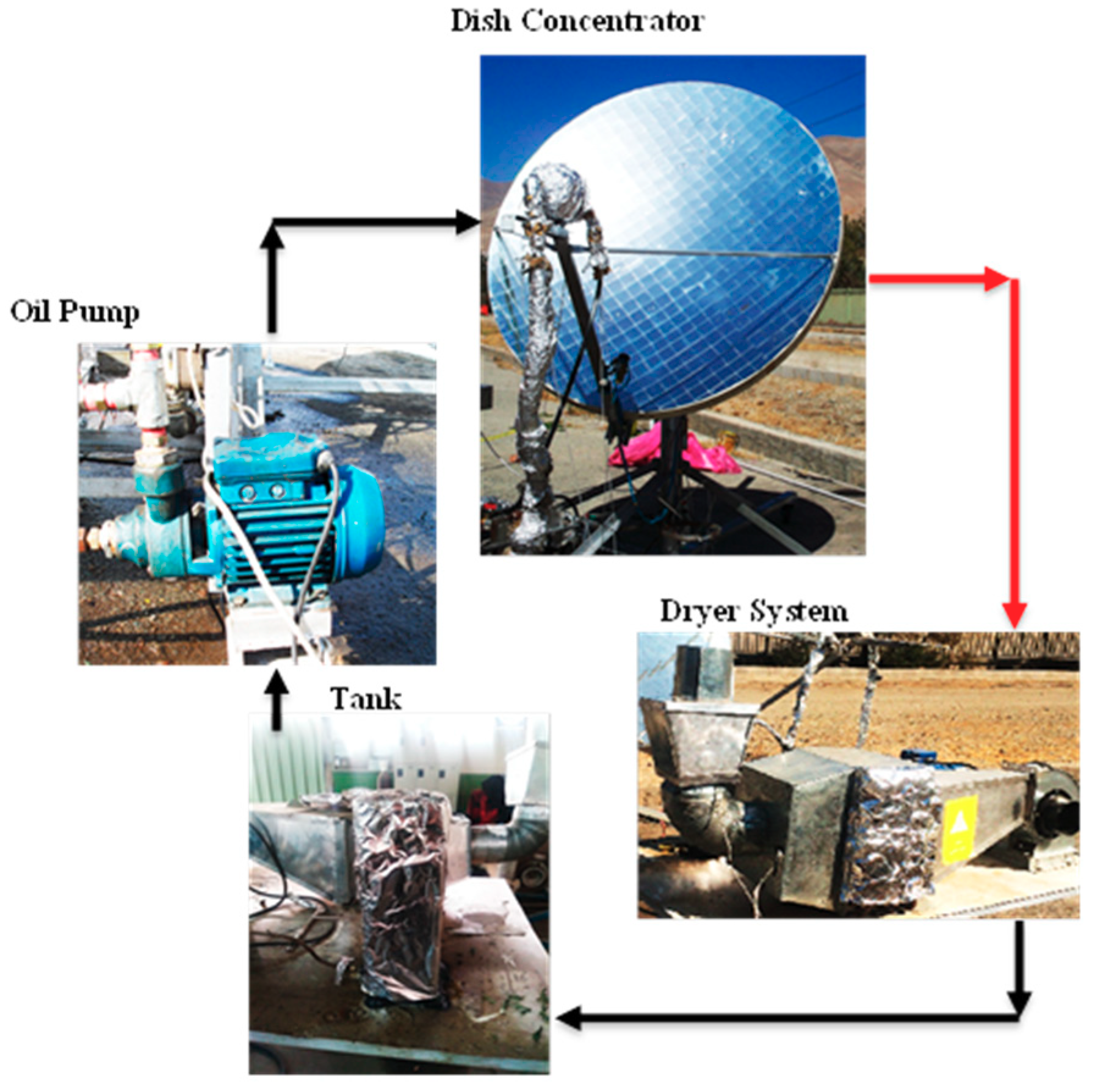
Figure 1. A view of different parts of the experimental setup.
Energies 12 04747 g001
Figure 2. A view of the solar system: (a) the dish concentrator and (b) the cylindrical cavity receiver.
Energies 12 04747 g002
Figure 3. The solar dryer system.
Energies 12 04747 g003
Figure 4. A schematic view of the simulated dryer system.
Energies 12 04747 g004
Figure 5. A TEM picture of the alumina nanoparticles.
Energies 12 04747 g005
Figure 6. A view of the preparing Al2O3/thermal oil nanofluid by using (a) the stirrer device and (b) the ultrasonic system.
Energies 12 04747 g006
Figure 7. A view of color variation test of mint leaves.
Energies 12 04747 g007
Figure 8. Variation of solar radiation, ambient temperature, and oil temperature difference at inlet and outlet of the cavity during the experimental day 29 September 2017, with thermal oil as working fluid.
Energies 12 04747 g008
Figure 9. Variation of top wall temperature, sidewall temperature, and wind speed during the experimental day 29 September 2017, with thermal oil as the solar working fluid.
Energies 12 04747 g009
Figure 10. Variation of cavity heat gain and thermal efficiency of the solar system during the experimental day 29 September 2017, with thermal oil as the solar working fluid.
Energies 12 04747 g010
Figure 11. Variation of solar radiation, ambient temperature, and nanofluid temperature difference at the inlet and outlet of the cavity receiver during the experimental day 30 September 2017, with Al2O3/thermal oil nanofluid as the working fluid.
Energies 12 04747 g011
Figure 12. Variation of top wall temperature, sidewall temperature, and wind speed during the experimental day 30 September 2017, with Al2O3/thermal oil nanofluid as the working fluid.
Energies 12 04747 g012
Figure 13. Variation of cavity heat gain and thermal efficiency of the solar system during the experimental day 30 September 2017, with Al2O3/thermal oil nanofluid as the working fluid.
Energies 12 04747 g013
Figure 14. Comparison of cavity heat gain using pure thermal oil and Al2O3/thermal oil nanofluid as working fluid during experimental tests.
Energies 12 04747 g014
Figure 15. Comparison of thermal efficiency of the cavity receiver using pure thermal oil and Al2O3/thermal oil nanofluid as working fluid during experimental tests.
Energies 12 04747 g015
Figure 16. Mint drying graph at air speed of 0.5 m/s and different drying temperatures.
Energies 12 04747 g016
Figure 17. Mint drying graph at air speed of 1 m/s and different drying temperatures.
Energies 12 04747 g017
Figure 18. Mint drying graph at air speed of 1.5 m/s and different drying temperatures.
Energies 12 04747 g018
Figure 19. Variation of air speed at different air inlet speeds: (a) 0.5 m/s, (b) 1 m/s, and (c) 1.5 m/s.
Energies 12 04747 g019
Figure 20. Variation of streamlines at different air inlet speeds: (a) 0.5 m/s, (b) 1 m/s, and (c) 1.5 m/s.
Energies 12 04747 g020
Figure 21. Comparison between numerical and experimental results of the current research.
Energies 12 04747 g021
Figure 22. Color histogram of the wet mint based on the RGB method.
Energies 12 04747 g022
Figure 23. Color histogram of the dried mint at air inlet speed of 1 m/s and inlet temperature of 40 °C based on the RGB method.
Energies 12 04747 g023
Figure 24. Color histogram of the dried mint at air inlet speed of 1 m/s and inlet temperature of 50 °C based on the RGB method.
Energies 12 04747 g024
Table 1. The specification of the dish concentrator and cylindrical cavity receiver.
Structural DimensionsValues
Dish Concentrator
Aperture diameter2 m
Focal length0.693 m
Tracking error
Rim angle45°
Concentration ratio165
Focal length0.693 m
Cylindrical Cavity Receiver
Outer diameter16 cm
Inner diameter14 cm
Height14 cm
Number of tube turns at the cavity height14
Inner tube diameter10 mm
Table 2. Accuracies and ranges of the measuring instruments.
Sl. No.InstrumentAccuracyRange% Error
1PT-100 sensor±1.35 °C−200 to 400 °C0.25
2Solar power meter±0.1 W/m20 to 2000 W/m20.25
3Anemometer±0.2 m/s0.9 to 35.0 m/s10
Table 3. Suggested experimental relationships for prediction of moisture ratio versus time for different air speeds and drying temperatures.
Air Speed (m/s)Drying Temperature (ºC)Predicted Experimental RelationshipR2
0.530y = 5 × 10⁻⁶∙x2 − 0.0047x + 1.01620.9951
0.540y = 5 × 10−4x4 − 4 × 10−7x3 + 9 × 10−5x2 − 0.0119x + 1.00850.9989
0.550y = −5 × 10−7x3 + 5 × 10−5x2 − 0.0104x + 0.96920.9943
1.030y = 4 × 10−6x2 − 0.0044x + 1.01030.9969
1.040y = 7 × 10−6x2 − 0.0052x + 0.96120.9941
1.050y = −2 × 10−8x3 + 2 × 10−5x2 − 0.0079x + 0.9850.9974
1.530y = 5 × 10−6x2 − 0.0047x + 0.99330.9992
1.540y = 9 × 10−6x2 − 0.0056x + 0.93970.9927
1.550y = 2 × 10−10x4 − 2 × 10−7x3 + 5 × 10−5x2 − 0.0106x + 0.98090.9969