Article

Analysis of Grid-Connected Photovoltaic Generation Systems in the Harmonic Domain

by
Marcolino Humberto Díaz-Araujo
1,
Aurelio Medina-Rios
1,*,
Manuel Madrigal-Martínez
2 and
Luis Arthur Cleary-Balderas
1
1
Facultad de Ingeniería Eléctrica, División de Estudios de Posgrado, Universidad Michoacana de San Nicolás de Hidalgo (UMSNH), Morelia, Michoacán, CP 58030, Mexico
2
Programa de Graduados e Investigación en Ingeniería Eléctrica, Instituto Tecnológico de Morelia, Morelia, Michoacán, CP 58030, Mexico
*
Author to whom correspondence should be addressed.
Energies 2019, 12(24), 4785; https://doi.org/10.3390/en12244785
Submission received: 1 November 2019 / Revised: 27 November 2019 / Accepted: 12 December 2019 / Published: 16 December 2019
(This article belongs to the Section A1: Smart Grids and Microgrids)

Abstract

:
In this contribution, a harmonic domain (HD) model of grid-connected photovoltaic (PV) generation systems is proposed. The topology of the PV generation system contains a PV array connected to a DC/DC converter and a DC/AC converter, coupled to the grid through a filter. The individual components of the PV system are modeled in the HD. The PV array is represented as a Thevenin equivalent, whereas the DC/DC converter and the DC/AC converter are represented in the HD using switching function matrices. The periodic steady-state solution of the PV system is obtained through simple matrix/vector operations. The results obtained by the proposed model are validated against the response obtained with the PSCAD/EMTDC® simulator, widely accepted by the power industry.

1. Introduction

Worldwide societies are increasingly concerned with the already powerful effects of climate warming. By the end of 2018 and over the course of 2019, atypical weather phenomena have taken place around the world, e.g., powerful hurricanes, droughts, floods, forest fires, and massive kelp arrival in coasts, all of them related to climate change due to the irrational consumption of fossil fuels and their polluting subproducts. Electrical energy generated in power plants using such fuels is one of the main causes of pollution and climate change around the world. Therefore, a fast transition to renewable energy sources is imperative, while the demand for electrical energy is continuously increasing to satisfy the multiple needs of growing societies and their associated industrial infrastructure.
Among the alternatives of renewable energy sources, photovoltaic (PV) technology is fast developing. It includes several technical aspects related to the dynamic operation, control, and power quality issues, among others. The above can be adequately assessed through the development and use of appropriate simulation models [1].
Successful examples of development of large PV systems have been reported [2,3] with their integration with the power network considered. An area of opportunity deals with the development of small PV energy systems and secondary energy sources, such as capacitor/battery banks and diesel generators [4,5,6]. PV systems are usually conveniently interfaced to the grid/load through converter arrangements; i.e., for their isolated operation [7,8] or grid-connected performance [9]. Efficiency and safety are important issues to be considered during the operation of PV systems. In particular, it has been observed that the efficiency may decline due to losses associated with the transformer operation and other auxiliary components. Alternative arrangements based on the elimination of transformers and isolated sensors may contribute to solve this problem and to reduce costs [10].
The reasons mentioned above have encouraged the modeling and analysis of electrical grids of generation with renewable energy sources under transient and/or periodic steady-state operation. This research is in particular centered on the periodic steady-state modeling and analysis of grids with PV sources in the harmonic domain (HD).
Traditionally, time-domain (TD) methods have been used to simulate grid-connected PV systems where a postprocessing stage is needed for the extraction of harmonics. This, in fact, is performed after the transient has died out and the periodic steady-state solution has been obtained. However, for lighted damped systems, achieving the periodic steady-state solution may require long simulation times [11]. Newton methods have been proposed to speed up the solution in time domain in electronic circuits [12] and in electrical networks [13]. The method described in [12] is referred to as the shooting method, and those proposed in [13] are referred to as Newton methods of extrapolation to the limit cycle based on Poincaré maps [14]. Their use and application are at present consolidated, based on the several applications reported for the efficient periodic steady-state solution of nonlinear and time-varying components and electrical networks [15]. In particular, in a recent contribution [16], the periodic steady state of a microgrid with PV generation is obtained in the time domain using a Newton method [13] and cubic splines.
As an alternative, the HD framework [17,18,19] is a consolidated powerful alternative for the determination of the periodic steady-state solution of nonlinear power networks. The harmonic domain concept was formally introduced in [17] to describe a general frame of reference for harmonic analysis with phases, harmonics, and harmonic cross-coupling, where linear and nonlinear components and effects of the power network were explicitly represented in a unified framework representation for their periodic steady-state solution of the entire electric network. Later references [18,19] reported the progress achieved in the harmonic domain in power network modeling and analysis. A more recent contribution [15] concisely details the procedure of linearization of nonlinear power components and the unified solution of linear and nonlinear networks in the harmonic domain. This is the approach followed in the research reported in this contribution. In recent contributions [20,21,22] the HD concept is used to report the modeling of aspects related to the connection of PV systems to the grid under harmonic distortion conditions. In another recent contribution in the frequency domain [23], the harmonics produced by the voltage ripple in a PV inverter with feedback control are analyzed. In [24], a model is proposed to assess the harmonic distortion produced from grid-connected PV inverters.
The paper is detailed in the sections to follow as: Section 2 describes the modeling of grid-connected PV generation system, Section 3 details the state-space TD representation of the total PV system, Section 4 presents the HD model, Section 5 shows a flowchart of the overall solution process, Section 6 shows a test-case solution with the proposed HD methodology and its validation against the simulator PSCAD/EMTDC®, widely accepted by the power industry, and Section 7 gives the overall conclusions of this investigation.

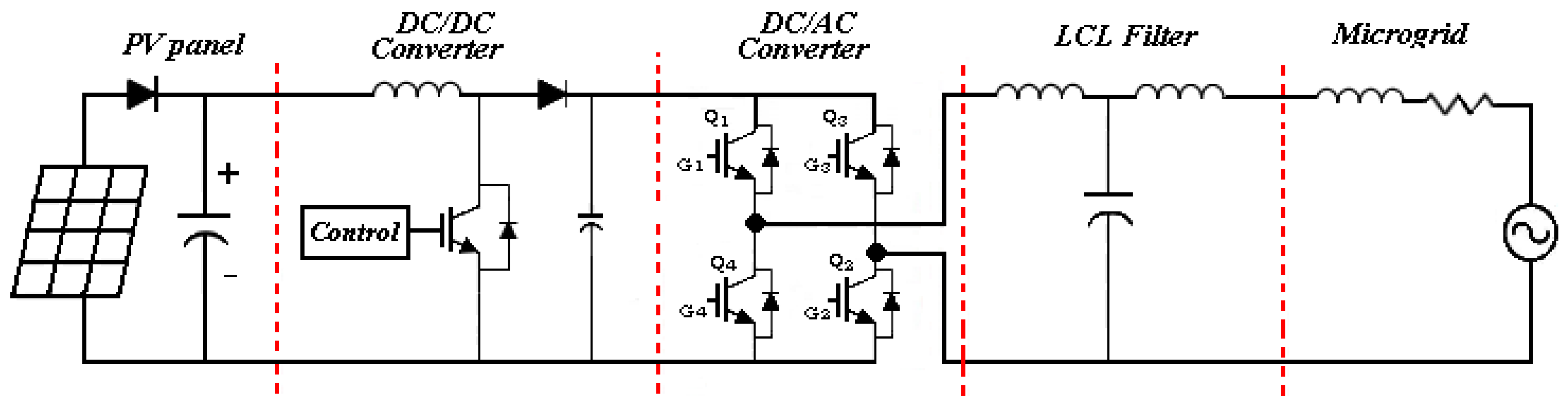
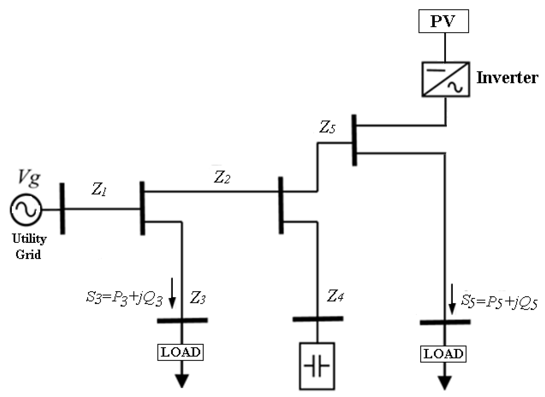
2. System Configuration

In Figure 1, a single-phase grid-connected PV system is connected to a utility grid through a PV array, a capacitor link, a DC/DC and DC/AC converter, and a filter.
The decoupling AC-system dynamics from the PV array is achieved through the capacitor connected at the PV array output. The voltage level and maximum power point tracking (MPPT) of the PV array is achieved with the DC/DC converter; the DC/AC converter allows to obtain the AC power. The grid-connected PV inverters should satisfy the grid code, i.e., the network connection criteria, construction of the power generation system/network, system protection, and operation of the system [25]. A filter is used to mitigate the total harmonic distortion (THD) at the point of common coupling (PCC) with the PV system. The HD model of a single-phase PV system connected to a grid is described next.

2.1. PV System Representation

A PV device is an element that converts sunlight into electricity. A PV cell is the basic unit of a PV device; an arrangement of series-parallel connected cells form a module. Figure 2 shows the equivalent circuit of a PV module. The equation that mathematically describes the characteristic of a PV module is [26,27]:
I = I p v I 0 [ e x p ( V + R s I a V T ) 1 ] V + R s I R p ,
where I 0 and I p v are the saturation and generated PV currents of the PV module, respectively, VT = N S k T / q is the thermal voltage of the array with N S cells in series, I d is the Shockley diode current, being the second term in Equation (1), q is the electron charge (1.60217646 × 10⁻²³ J/K), T is the p–n junction temperature (Kelvin), a is the ideal diode constant, R P is the equivalent parallel resistance, and R S is the equivalent series resistance of the PV array.
In this research work, a PV array is represented as a PV Thevenin equivalent, obtained with the calculation of the R P and R S parameters of Figure 2. The above is achieved by solving the nonlinear relation, Equation (1), with the PV array working at maximum power point (MPP).
The PV Thevenin equivalent is calculated as follows:
Step 1. In a PV array, V O C and I S C are given by the number of series and parallel cells. The total PV array characteristics are calculated as:
V O C = N s V ,
V M P P = N s V m p p ,
I S C = N p I s c ,
I M P P = N p I m p p .
Step 2. It is assumed that I p v is equal to the maximum generated current I s c , and I 0 is calculated as:
I 0 = I S C e x p V O C a V T 1 .
Step 3. With the PV array working at MPP, IMPP is given by:
I M P P = I p v I 0 ( e x p V M P P + I M P P R S a V T 1 ) V M P P + I M P P R s R p ,
from the P–V curve of a PV module, the derivative of the power with respect to voltage is zero at MPP, i.e.,
I M P P R s V M P P a V T I 0 e x p V M P P + I M P P R S a V T + I M P P ( R s R p + 1 ) V M P P R S = 0 ,
by applying the Newton–Raphson (NR) method to the simultaneous solution of Equations (7) and (8), R S and R P can be obtained.
Step 4. With R S and R P known, and using the Thevenin theorem, the equivalent voltage source is calculated as:
V t h = R p [ I P V I o ( e x p ( V + R s I a V T ) 1 ) ] .
The equivalent resistance is:
R t h = R p + R s .
Equations (9) and (10) represent the resultant Thevenin equivalent to be interfaced.

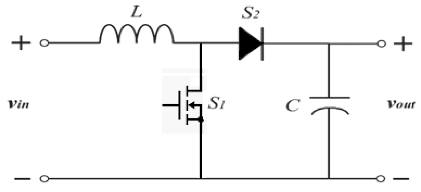
2.2. Boost Converter

The boost converter (BC) is shown in Figure 3. It maintains the output voltage v o u t at the desired level, based on the input voltage v i n and the load, which may fluctuate. The output voltage is higher than the input voltage.
The diode is reverse biased when the switch is “on” and the output stage is isolated. The input supplies energy to the inductor. If the switch is “off”, the output stage receives energy from the inductor and from the input. The switch is controlled by a pulse-width modulation (PWM) technique with a duty ratio d, determined as,
d = T o n T s ,
which is adjusted as needed [26]. In Equation (8), TS is the BC switching period, being of the order of kHz [28]; T o n is the time the switch remains in “on” state.

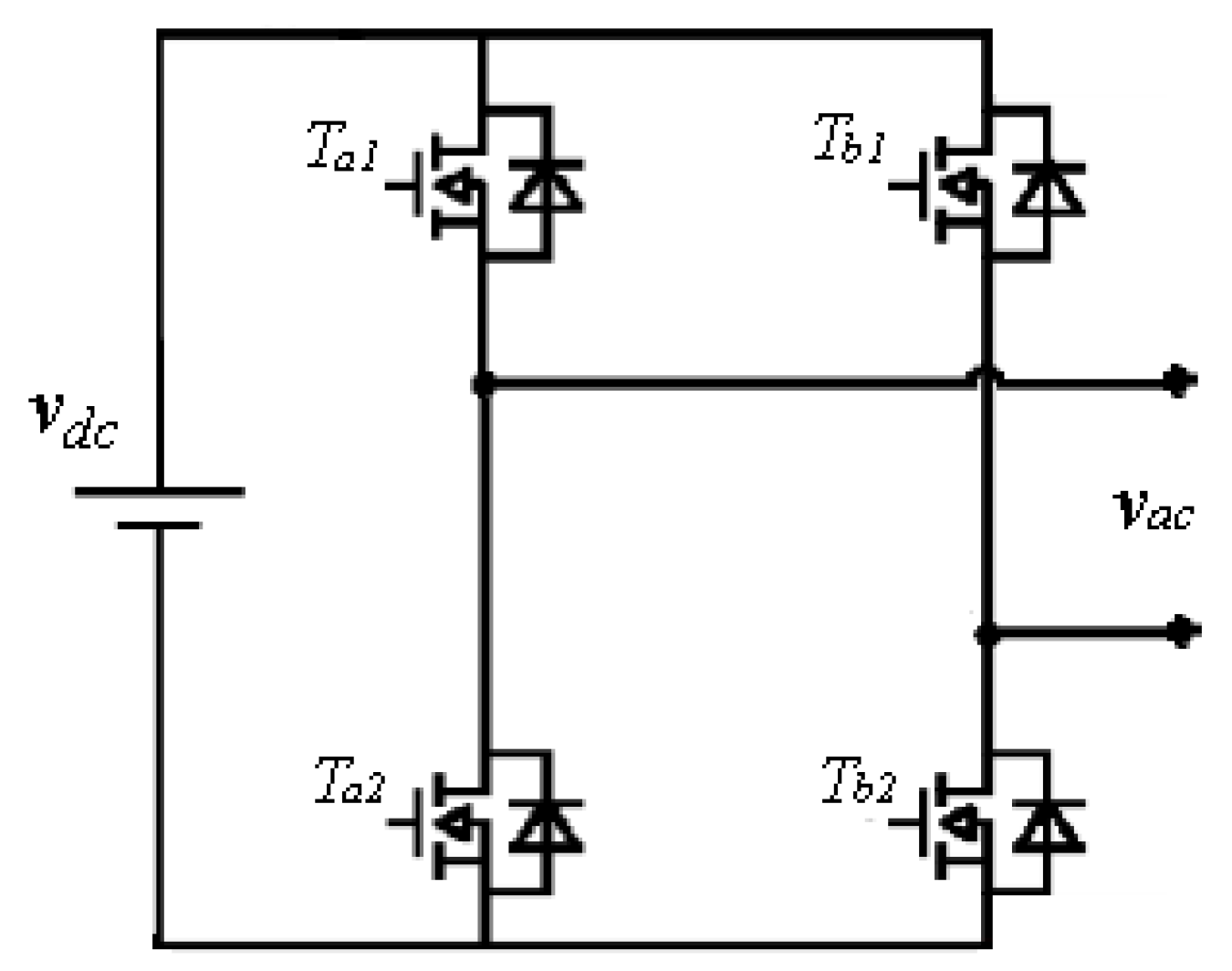
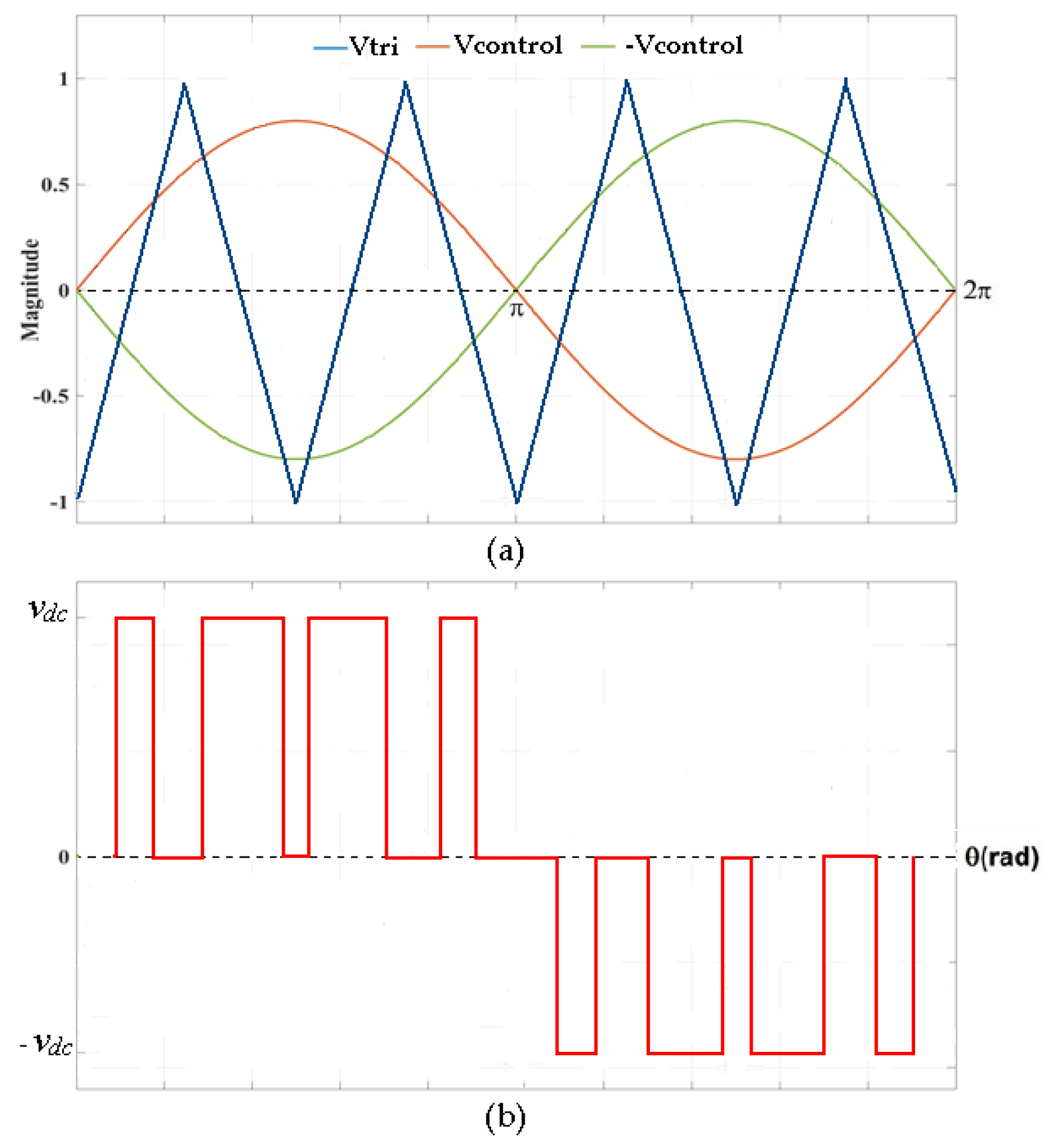
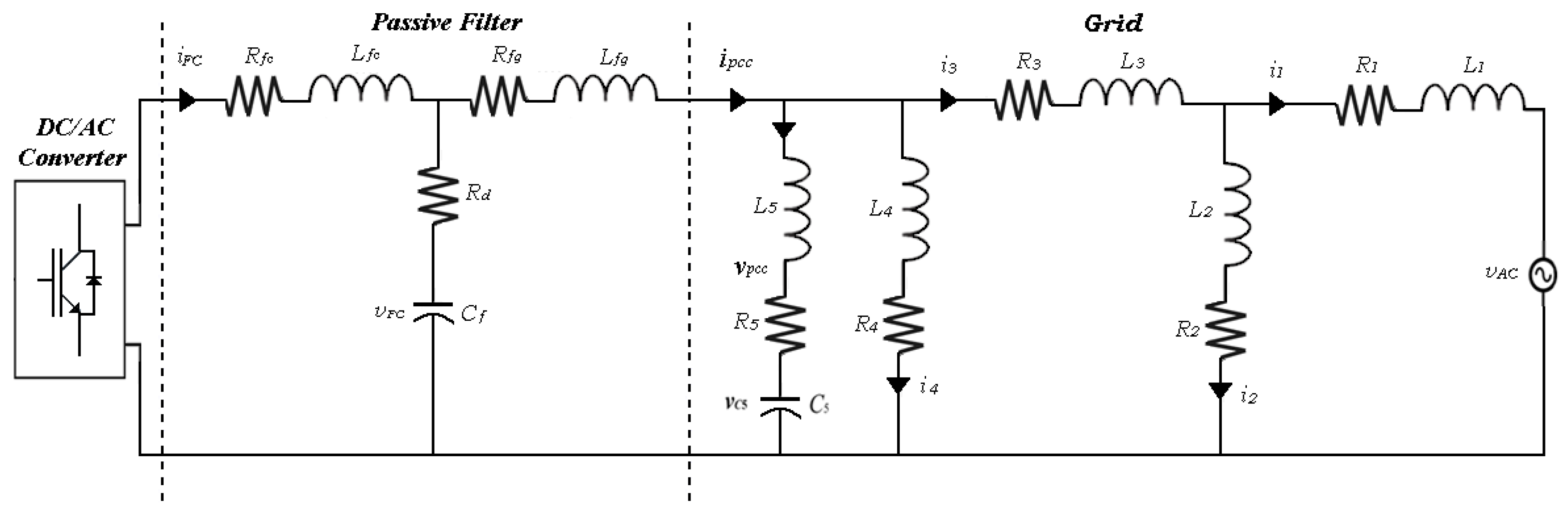
2.3. DC/AC Converter

The single-phase full-bridge inverter DC/AC shown in Figure 4 generates a sinusoidal AC output voltage. Switching of the inverter voltage is based on the PWM technique, where two sinusoidal waveforms and a high-frequency triangular carrier waveform are used to generate the PWM signal [26]. The PWM signal is obtained through comparison of the triangular waveform V t r i against V c o n t r o l and V c o n t r o l as shown in Figure 5a. The reference voltage and carrier intersection through the peak value of V c o n t r o l (and V c o n t r o l ) is shown in Figure 5b. The modulation ratio m a is calculated as:
m a = V c o n t r o l V t r i ,
m a is also the ratio between the magnitude of the fundamental component of the output voltage V a c and the input voltage V d c . The frequency of V t r i is on the order of several kHz and defines the order of the harmonics of V a c [27]. Harmonics in V a c appear as sidebands, each centered at twice the frequency modulation ratio m f , i.e.,
m f = f s f 0 ,
where fs is the switching frequency and f0 is the AC-system frequency. For the unipolar PWM voltage switching in the voltage source inverter (VSI), the control of leg A is independent of the control for leg B. For instance, in leg A, when V c o n t r o l < V t r i , S 1 is turned on, otherwise it is turned off ( S 2 is complementary to S 1 ). The same applies for the control of leg B, but using V c o n t r o l instead of V c o n t r o l .

3. State-Space Representation of the Grid-Connected PV Generation System

Figure 6 shows the single-phase diagram of a grid-connected PV system. It consists of a voltage source, five transmission lines, a capacitor bank, two linear loads, and the PV array. The associated equivalent circuit is shown in Figure 7. The PV source has been replaced by the corresponding Thevenin equivalent, as explained in Section 2.
Twelve differential algebraic equations (DAE), i.e., six differential equations and six algebraic equations represent the dynamic operation of the grid-connected PV system. The voltage at the capacitors and the currents in the inductors are selected as the state variables. The DAE set is detailed next.
Differential equations:
d d t V p v = V p v C p v R p v I L C p v + V D C C p v R p v ,
d d t I L = V p v L V C L S 2 ,
d d t V c = I L C S 2 I F C C S i ,
d d t I F C = V C L f c S i ( R f c + R d ) L f c i F C V C F L f c + R d L f c i f c c ,
d d t V C F = I F C C f I P C C C f ,
d d t V c 5 = i 5 C 5 .
Algebraic equations:
d d t i p c c = D 3 B 3 ( 1 + L 1 L 2 ) L 3 + L 1 ( L 2 + L 3 ) L 2 , 1 ( L 4 L 5 + 1 ) ( L f g L 4 ) L f ( 1 + L 1 L 2 ) L 3 + L 1 ( L 2 + L 3 ) L 2 ,
d d t i 5 = d d t i 4 · L 4 L 5 C 1 L 5 ,
d d t i 4 = E L 4 d d t i I P C C · L f g L 4 + C 1 L 4 ,
d d t i 3 = d d t i 2 + d d t i 1 ,
d d t i 2 = d d t i 1 · L 1 L 2 A L 2 ,
d d t i 1 = B 3 L f g d d t i P C C L 3 + L 1 ( L 2 + L 3 ) L 2 ,
where:
A = i 2 R 2 i 1 R 1 V A C ,
B = i 4 R 4 i 3 R 3 i 2 R 2 ,
C 1 = i 5 R 5 + V C 5 i 4 R 4 ,
E = ( i F C i I P C C ) R d + V C F i I P C C R f g i 5 R 5 V C 5 ,
B 3 = B + ( L 2 + L 3 ) L 2 A + C 1 + E ,
D 3 = ( 1 + L 4 L 5 ) · E L 4 ( 1 + L 4 L 5 ) · C 1 L 4 + C 1 L 5 + A L 2 .

4. Harmonic Domain Model

The grid-connected PV system of Figure 7 can be solved in the TD with a state-space matrix equation representation based on nonautonomous ordinary differential equations of the form:
X ˙ = [ A ] X + [ B ] u ,
where [ A ] is the state matrix of size n × n , [ B ] is the control or input matrix of size n × r , and u is the input vector of dimension r .
Based on [6], the set of ordinary differential equations given by Equation (32) is conveniently converted into the HD following the procedure detailed in [18] resulting in:
[ D d ] X = [ A ] X + [ B ] u ,
where:
[ D ] = [ 0 0 0 0 0 0 - j ω 0 0 0 0 0 0 0 0 0 0 0 0 0 0 j ω 0 0 0 0 0 0 0 - j 2 ω 0 0 0 0 0 0 0 ]
[ D d ] = [ 0 0 0 0 0 0 D 0 0 0 0 0 0 D 0 0 0 0 0 0 D 0 0 0 0 0 0 D 0 0 0 0 0 0 ]
X = [ V P V I L V C I F C V C F ]
[ A ] = [ - 1 C p v R p v I d - 1 C p v I d 0 0 0 1 L I d 0 - 1 L S 2 0 0 0 1 C S 2 0 - 1 C S i 0 0 0 1 L f c S i - ( R f c + R d ) L f c I d - 1 L f c I d 0 0 0 1 C f I d 0 ]
and:
[ B ] u = [ 1 C p c R p v 0 0 0 0 ] .
In Equation (35) the differentiation matrix D has been arranged in block-diagonal form to account for the twelve HD variables. Also, the switching functions S i = S 1 S 2 and S 2 are represented in the HD as Toeplitz-type matrices S i and S 2 , respectively, and introduced into matrix [A] (Equation (37)). Note that in Equation (37) I d represents an identity matrix of appropriate dimensions.
Alternatively, for the HD solution of Equation (33), the steady-state solution of the PV system for a given operating point can be obtained as:
X = ( [ D d ] [ A ] ) 1 [ B ] u .
In practical applications, the PV system must operate around the MPP. This can be achieved by an appropriate duty ratio of the BC. The switching function of the BC has been included in Equation (39) as a Toeplitz-type matrix for a given duty ratio. The solution of Equation (39) with any duty ratio leads to an operating point possibly different than the MPP. Then, an iterative solution scheme is needed. Figure 8 shows the proposed scheme. Generally speaking, Figure 8 shows that the HD system Equation (39) is solved for a given duty ratio and the MPP operating condition is assessed. In case that the response is negative, the duty ratio is increased or decreased based on a perturb and observe algorithm to achieve the MPP. In the flow diagram of Figure 8, V p v 0 and I p v 0 correspond to the DC components of the HD vectors V p v and I p v , respectively. Also, Δd represents an increment (or decrement) of the duty ratio of S 1 . In our research we assumed d = 0.25 and a tolerance for convergence of 0.001 p.u.

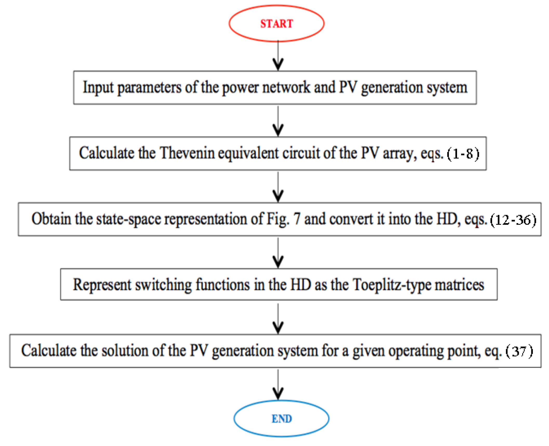
5. Flowchart of HD Solution

In practical applications, the PV system must operate around the MPP. This can be achieved by an appropriate duty ratio of BC. In this research work, the perturb and observe algorithm is used to reach the MPP. Furthermore, the modeled PV system is a non-feedback system, i.e., the output of the system has no influence or effect on the control action of the input signal. In other words, it is an open-loop system. The switching function of the BC has been included in Equation (28) as a Toeplitz-type matrix for a given duty ratio.
The flowchart of the solution process to obtain the periodic steady-state solution of grid-connected PV sources in the HD is shown in Figure 9. It has five blocks, where in the first block the parameters of the network, including the PV system, are read; in the second block, the Thevenin equivalent circuit of the PV array is calculated; in the third block, the set of ODEs is obtained from the circuit of Figure 7 and converted to the HD. In the fourth block the switching functions are represented in the HD as Toeplitz-type matrices and introduced into the matrix [A]. Finally, in the fifth block, the solution of the PV generation system for a given operating point is calculated. Through this procedure, the periodic steady-state solution of the entire grid is obtained via simple matrix/vector operations.

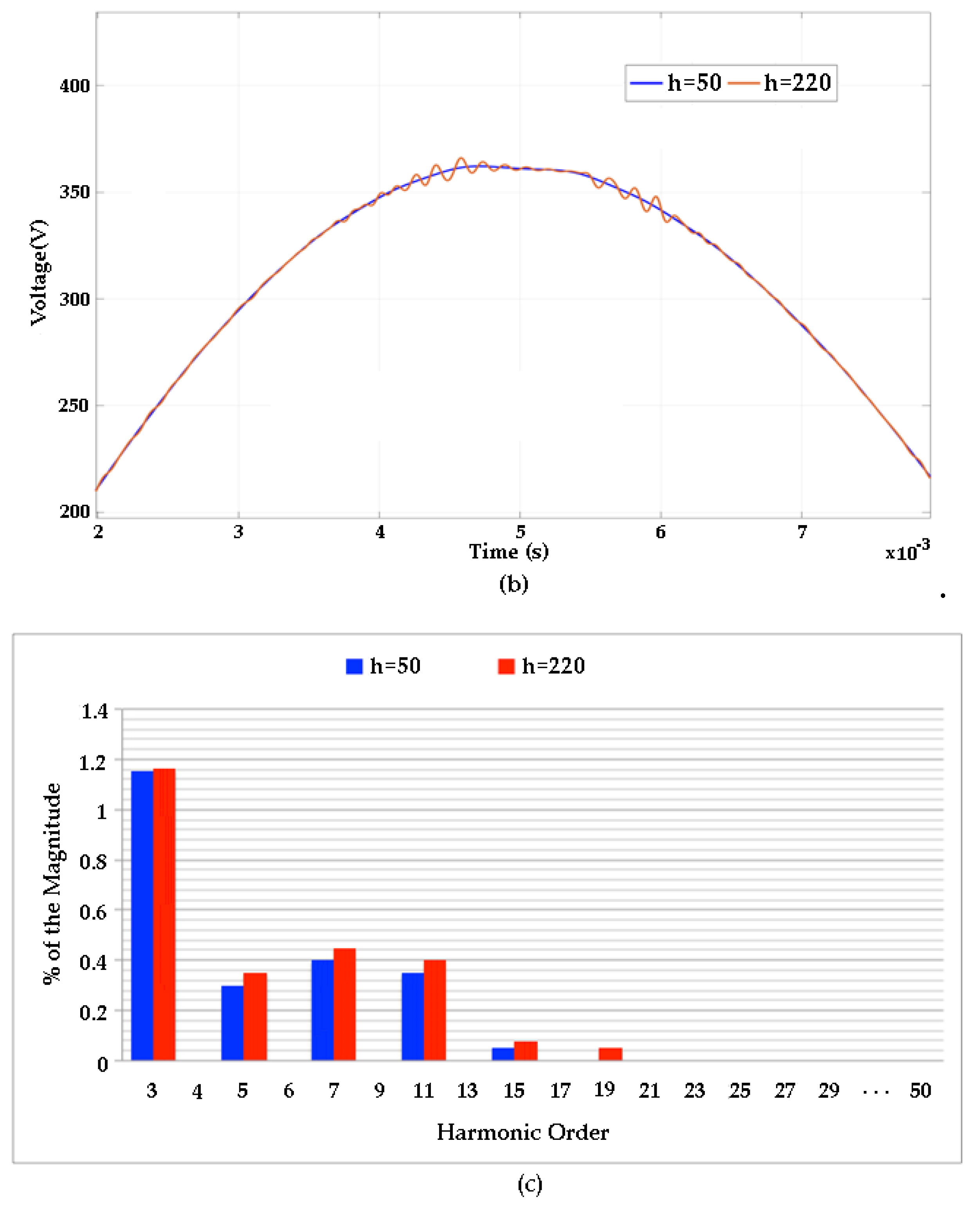
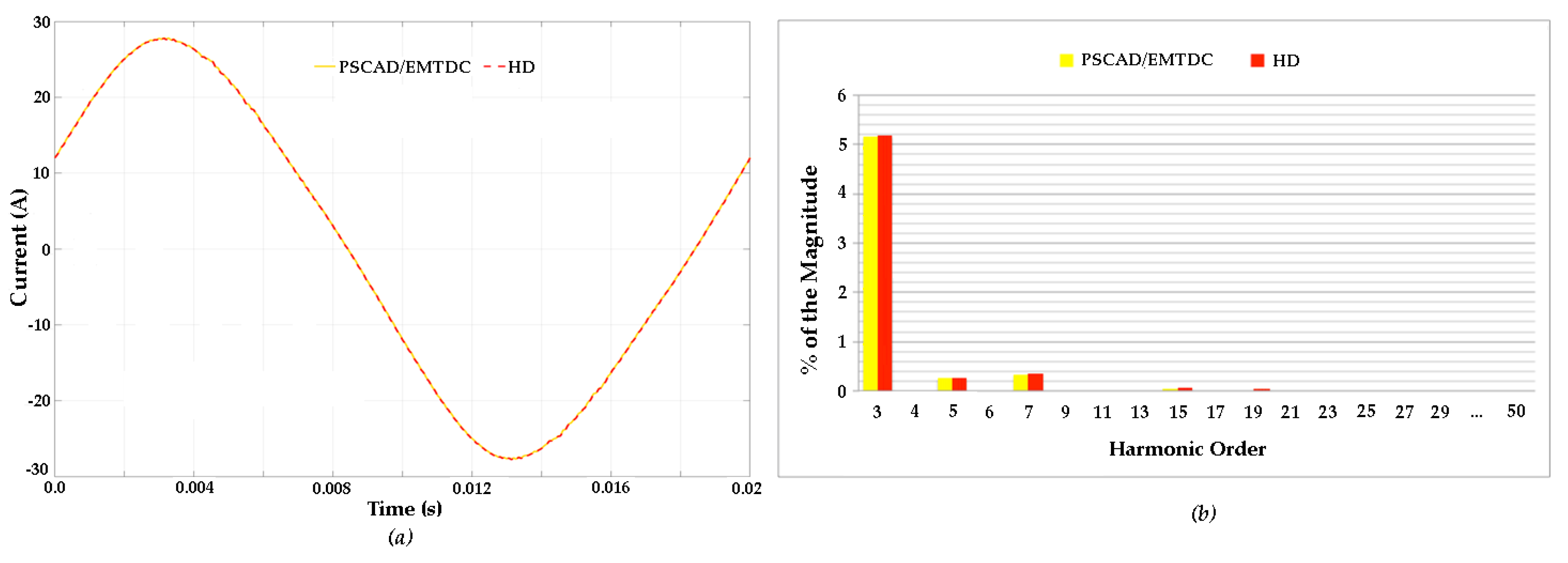
6. Simulation Results

The grid-connected PV system shown in Figure 7 is used as a test system. The corresponding parameters are given in Table A1 of Appendix A. Standard test conditions (STC) in the PV array are assumed, i.e., 1000 W/m2 and 25 °C, with the PV system operating at MPP.
Figure 10 shows the resultant TD waveforms and the corresponding harmonic content of the voltage at PCC. It is remarked that to obtain the TD waveforms presented in this section, Equation (28) is evaluated with a sampling time-step of 0.1 μs. The results of Figure 10 have been obtained by considering the explicit representation of 50 and 220 harmonics, respectively, in the HD model of the PV system. It can be noticed that higher order harmonics produced by power electronics components are not expected to appear beyond the twentieth harmonic.
By comparing the individual harmonics obtained in the HD with the explicit representation of 50 harmonics, it is clear that all meet the IEEE 1547-2018 standard [25]. In the absence of a harmonic resonance, it is sufficient to explicitly represent in the HD solution the presence of the first 25 or at most 50 harmonics, thus dramatically reducing the required computational effort needed without losing accuracy in the HD solution.
The calculated THD and powers at PCC are listed in Table 1. The maximum error between responses obtained with the HD method and the PSCAD/EMTDC® simulator is negligible, i.e., it is only 0.02% for the THD in the variable i P C C . The current waveform at PCC is illustrated in Figure 11a and the corresponding comparison in harmonic content is shown in Figure 11b. Again, a close agreement between responses can be observed. It is shown that the harmonic distortion of the waveform is mainly due to the presence of third, fifth, and seventh harmonics, these being of 5.12%, 0.15%, and 0.26%, respectively. The third harmonic (5.12%) exceeds the permissible limit set by the IEEE 1547-2018 standard [25], which is 4%.

7. Conclusions

A model of a grid-connected PV generation system in the harmonic domain has been proposed. It has been evaluated for standard test conditions (STC). The proposed model can include any number of harmonics depending on the desired resolution. However, according to the obtained results, it should be noticed that in the absence of higher frequency resonances, using a smaller harmonic spectrum may represent a considerable reduction in the required computational resources to obtain the HD solution.
A major characteristic of the proposed model is that the periodic steady state can be obtained in a direct way through a solution process in the HD. Here, switching functions (of the BC and inverter) are represented in the HD as Toeplitz-type matrices.
This contribution is relevant since the developed method allows the determination of the periodic steady-state solution in networks with photovoltaic generation systems in the harmonic domain, which is a frame of reference that allows an accurate prediction of individual harmonics and total harmonic distortion (THD) of voltage and current through a unified solution where harmonics and harmonic cross-coupling effects are explicitly represented.
The reported results allow a precise assessment of individual harmonic magnitudes and THD, which indicates that the continuous operation of PV units in the electrical network is related with harmonics that may exceed permissible limits set by established standards.
The obtained results have been successfully validated against the response obtained with the PSCAD/EMTDC® simulator, widely accepted by the power industry. A close agreement between the obtained responses has been obtained in all cases.

Author Contributions

M.H.D.-A.; contributed with methodology, formal analysis, investigation, software, validation, original draft. A.M.-R.; contributed with methodology, conceptualization, funding acquisition, project administration, review and editing. M.M.-M.; contributed with conceptualization, methodology, formal analysis and review. L.A.C.-B.; contributed with visualization, review and editing.

Funding

This research was funded by CONACYT project number 275495.

Acknowledgments

The authors want to acknowledge CONACYT for finance assistance to conduct this investigation and to the Facultad de Ingeniería Eléctrica, División de Estudios de Posgrado, UMSNH, Morelia, México for the access and use of its facilities.

Conflicts of Interest

The authors declare no conflict of interest.

Appendix A. Test Case Parameters

Table A1. Data of Grid-Connected PV Generation System.
PV Array at STC
N S 17Number of modules connected in series
N P 2Number of modules connected in parallel
V O C 21.47 VOpen-circuit voltage per module
I S C 7.6 AShort-circuit current per module
V M P P 17.1 VVoltage at MPP per module
I M P P 7.1 ACurrent at MPP per module
P m a x 121.41 WMaximum power per module
n S 28Number of cells connected in series per module
a1.3Ideality factor of diode
DC/DC Converter
C p v 5500 μFCapacitance
L9 mHInductance
C2200 μFCapacitance
F S 10 kHzSwitching Frequency
DC/AC Converter
F S 25 kHzSwitching Frequency
m a 0.9Modulation index
Filter
R f c 1 mΩResistance
L f c 0.3 mHInductance
R f g 1 mΩResistance
L f g 0.15 mHInductance
C d 2 ΩResistance
C f 2.2 μFCapacitance
Grid
V A C 230 VVoltage (RMS)
R 1 1 ΩResistance
R 2 33 ΩResistance
R 3 1 ΩResistance
R 4 33 ΩResistance
R 5 1 ΩResistance
L 1 1 mHInductance
L 2 0.17 HInductance
L 3 1 mHInductance
L 4 0.17 HInductance
L 5 1 mHInductance
C 5 220 μFCapacitance

References

  1. Willis, H.L.; Scott, W.G. Distributed Power Generation: Planning and Evaluation, 1st ed.; CRC Press: New York, NY, USA, 2000. [Google Scholar]
  2. Bucher, M. Solarpark Ammerland, Oldenburg, Niedersachsen, Deutschland. Available online: www.martin-bucher.de (accessed on 2 February 2018).
  3. ESCO Pacific. Ross River Solar Farm, Queensland, Australia. Available online: www.rossriversolarfaarm.com.au (accessed on 9 February 2018).
  4. Eltawil, M.A.; Zhao, Z. Grid-connected photovoltaic power systems: Technical and potential problems—A review. Renew. Sustain. Energy Rev. 2010, 14, 112–129. [Google Scholar] [CrossRef]
  5. Kim, S.-K.; Jeon, J.-H.; Cho, C.-H.; Kim, E.-S.; Ahn, J.-B. Modeling and simulation of a grid-connected PV generation system for electromagnetic transient analysis. Sol. Energy 2009, 83, 664–678. [Google Scholar] [CrossRef]
  6. Perera, B.K.; Pulikanti, S.R.; Ciufo, P.; Perera, S. Simulation model of a grid-connected single-phase photovoltaic system in PSCAD/EMTDC. In Proceedings of the 2012 IEEE International Conference on Power System Technology (POWERCON), Auckland, New Zealand, 30 October–2 November 2012; pp. 1–6. [Google Scholar]
  7. Tan, Y.T.; Kirschen, D.; Jenkins, N. A Model of PV Generation Suitable for Stability Analysis. IEEE Trans. Energy Convers. 2004, 19, 748–755. [Google Scholar] [CrossRef]
  8. Chen, L.-R.; Tsai, C.-H.; Lin, Y.-L.; Lai, Y.-S. A Biological Swarm Chasing Algorithm for Tracking the PV Maximum Power Point. IEEE Trans. Energy Convers. 2010, 25, 484–493. [Google Scholar] [CrossRef]
  9. Ahmed, S.S.; Mohsin, M. Analytical Determination of the Control Parameters for a Large Photovoltaic Generator Embedded in a Grid System. IEEE Trans. Sustain. Energy 2010, 2, 122–130. [Google Scholar] [CrossRef]
  10. Li, W.; Gu, Y.; Luo, H.; Cui, W.; He, X.; Xia, C. Topology Review and Derivation Methodology of Single-Phase Transformerless Photovoltaic Inverters for Leakage Current Suppression. IEEE Trans. Ind. Electron. 2015, 62, 4537–4551. [Google Scholar] [CrossRef]
  11. Dommel, H.W.; Yan, A.; Wei, S. Harmonics from Transformer Saturation. IEEE Trans. Power Deliv. 1986, 1, 209–215. [Google Scholar] [CrossRef]
  12. Aprille, T.; Trick, T. A computer algorithm to determine the steady-state response of nonlinear oscillators. IEEE Trans. Circuit Theory 1972, 19, 354–360. [Google Scholar] [CrossRef]
  13. Semlyen, A.; Medina, A. Computation of the periodic steady state in systems with nonlinear components using a hybrid time and frequency domain methodology. IEEE Trans. Power Syst. 1995, 10, 1498–1504. [Google Scholar] [CrossRef] [Green Version]
  14. Parker, T.S.; Chua, L.O. Practical Numerical Algorithms for Chaotic Systems; Springer: New York, NY, USA, 1989. [Google Scholar]
  15. Medina, A.; Segundo, J.; Ribeiro, P.; Xu, W.; Lian, K.L.; Chang, G.W.; Dinavahi, V.; Watson, N.R. Harmonic Analysis in Frequency and Time Domain. IEEE Trans. Power Deliv. 2013, 28, 1813–1821. [Google Scholar] [CrossRef]
  16. Díaz-Araujo, M.; Medina, A.; Cisneros-Magaña, R.; Ramírez, A. Periodic Steady State Assessment of Microgrids with Photovoltaic Generation Using Limit Cycle Extrapolation and Cubic Splines. Energies 2018, 11, 2096. [Google Scholar] [CrossRef] [Green Version]
  17. Arrillaga, J.; Lisboa, M.; Cavia, M.; Medina, A.; Sanchez, P. The Harmonic Domain. A frame of reference for power system harmonic analysis. IEEE Trans. Power Syst. 1995, 10, 433–440. [Google Scholar] [CrossRef]
  18. Acha, E.; Madrigal, M. Power System Harmonics: Computer Modelling and Analysis; John Wiley & Sons: Hoboken, NJ, USA, 2001. [Google Scholar]
  19. Arrillaga, J.; Watson, N.R. Power System Harmonics; John Wiley & Sons: Hoboken, NJ, USA, 2003. [Google Scholar]
  20. Nduka, O.S.; Pal, B.C. Harmonic Domain Modeling of PV System for the Assessment of Grid Integration Impact. IEEE Trans. Sustain. Energy 2017, 8, 1154–1165. [Google Scholar] [CrossRef] [Green Version]
  21. Nduka, O.S.; Pal, B.C. Harmonic characterisation model of grid interactive photovoltaic systems. In Proceedings of the 2016 IEEE International Conference on Power System Technology (POWERCON), Wollongong, Australia, 28 September–1 October 2016; pp. 1–6. [Google Scholar]
  22. John, M.; Mertens, A. Harmonic domain model of an open-loop controlled pwm converter. Inform. Autom. Pomiary Gospod. Ochr. Środowiska 2018, 8, 25–29. [Google Scholar] [CrossRef]
  23. Du, Y.; Lu, D.D.-C.; Chu, G.M.L.; Xiao, W. Closed-Form Solution of Time-Varying Model and Its Applications for Output Current Harmonics in Two-Stage PV Inverter. IEEE Trans. Sustain. Energy 2014, 6, 142–150. [Google Scholar] [CrossRef]
  24. Du, Y.; Lu, D.D.-C.; James, G.; Cornforth, D.J. Modeling and analysis of current harmonic distortion from grid connected PV inverters under different operating conditions. Sol. Energy 2013, 94, 182–194. [Google Scholar] [CrossRef]
  25. IEEE Std 1547-2018—IEEE Standard for Interconnection and Interoperability of Distributed Energy Resources with Associated Electric Power Systems Interfaces; IEEE Standard 1547-2018; IEEE: Piscatway, NJ, USA, 2018. [CrossRef]
  26. Villalva, M.; Gazoli, J.; Filho, E. Comprehensive Approach to Modeling and Simulation of Photovoltaic Arrays. IEEE Trans. Power Electron. 2009, 24, 1198–1208. [Google Scholar] [CrossRef]
  27. Mohan, N.; Underland, T.M.; Robbins, W.P. Power Electronics: Converters, Applications, and Design, 3rd ed.; John Wiley & Sons: Hoboken, NJ, USA, 2001. [Google Scholar]
  28. Luo, F.L.; Ye, H. Advanced DC/DC Converters, 2nd ed.; CRC Press: Boca Raton, FL, USA, 2016. [Google Scholar]
Figure 1. Single-phase grid-connected photovoltaic (PV) system.
Energies 12 04785 g001
Figure 2. Diode equivalent circuit of a PV module.
Energies 12 04785 g002
Figure 3. Boost converter.
Energies 12 04785 g003
Figure 4. Single-phase full-bridge inverter.
Energies 12 04785 g004
Figure 5. Pulse-width modulation (PWM) with unipolar voltage switching. (a) Carrier ( V t r i ) and fundamental frequency ( V c o n t r o l ) for unipolar PWM technique; (b) generation of gate pulses.
Energies 12 04785 g005
Figure 6. Grid-connected PV system.
Energies 12 04785 g006
Figure 7. Equivalent circuit of the grid supplied by a PV source.
Energies 12 04785 g007
Figure 8. PV system iterative solution in the harmonic domain (HD).
Energies 12 04785 g008
Figure 9. Flowchart of the grid-connected PV system solution in the HD.
Energies 12 04785 g009
Figure 10. Voltage waveform and harmonic current content at point of common coupling (PCC): (a) v P C C ; (b) zoom-in of v P C C ; and (c) harmonic current content.
Energies 12 04785 g010aEnergies 12 04785 g010b
Figure 11. Current waveform and harmonic content at PCC: (a) i P C C ; (b) harmonic content.
Energies 12 04785 g011
Table 1. HD simulation results.
PSCAD/EMTDCHD
THD in v P C C 1.16%1.17%
THD in i P C C 5.27%5.29%
P4.1350 kW4.1370 kWActive power
PF0.86670.8669Power factor

