Article

Innovative Modeling Approach for Li-Ion Battery Packs Considering Intrinsic Cell Unbalances and Packaging Elements

1
Department of Electrical and Computer Engineering, Sungkyunkwan University, 2066, Seobu-ro, Jangan-gu, Suwon-si 16419, Korea
2
Korea Electronics Technology Institute (KETI), 226, Cheomdangwagi-ro, Buk-gu, Gwangju 61011, Korea
*
Author to whom correspondence should be addressed.
Energies 2019, 12(3), 356; https://doi.org/10.3390/en12030356
Submission received: 10 January 2019 / Revised: 19 January 2019 / Accepted: 20 January 2019 / Published: 23 January 2019
(This article belongs to the Section D: Energy Storage and Application)

Abstract

:
In this paper, an innovative modeling approach for Li-ion battery packs is proposed by considering intrinsic cell unbalances and packaging elements. The proposed modeling method shows that the accurate battery pack model can be achieved if the overall influences of intrinsic cell unbalances and packaging elements are taken account. Concurrently, the proposed method takes a practical model structure, resulting in the reduction of computational burden in a battery management system. Furthermore, because the proposed method utilizes cell information without a manufactured battery pack, it can be helpful to design optimal battery packs. The proposed method is verified through simulation and experimental results of the Li-ion battery pack along with the battery cycler. In three test profiles, the mean absolute percentage errors and root mean square errors of the proposed pack model do not exceed 0.5% and 0.07 V, respectively.

1. Introduction

A battery model with high precision is strongly required in a battery management system (BMS) because most of the estimation algorithms for battery states are based on the battery model accuracy [1,2]. However, many studies in the literature focus on the battery cell modeling techniques, while demand for an accurate battery pack model has increased in various fields, such as energy storage systems and electric vehicles [3,4,5,6]. Because a battery pack is composed of cells connected in series and parallel and packaging elements, such as busbars, as described in Figure 1, the battery pack modeling techniques are inevitably more complicated than the cell modeling techniques. Furthermore, intrinsic cell unbalances in a battery pack, such as cell capacity deviation, make battery pack modeling techniques more challenging.
Conventional studies on battery pack modeling techniques can be categorized into two methods. The first method is to apply cell modeling techniques to the battery pack by considering the entire battery pack as a cell [7,8,9]. By regarding the influences of the intrinsic cell unbalances and packaging elements as lumped parameters, this method has a practical model structure. However, because the impedances of packaging elements cannot be separated from the internal impedances of the battery pack, the accuracy of existing algorithms that utilize the internal impedances can be undermined [10,11]. Furthermore, this method cannot contribute to an optimal design of the battery pack because it requires experiments on the battery pack manufactured.
The second method is to build a battery pack model by simply connecting individual cell models based on the series-parallel configuration of battery cells in a pack [12]. As this method builds a battery pack model without experiments on a manufactured pack, it can contribute to the optimal design of the battery pack by predicting the pack characteristics. Moreover, by modeling individual battery cells in the pack, the intrinsic cell unbalances are considered in this method. However, because the influences of the packaging elements are not considered, the battery pack model accuracy can be undermined. Furthermore, a considerable amount of time is required to simulate the battery pack model because its model structure—the sum of the individual cell models—is inevitably complicated.
In this paper, in order to overcome the disadvantages of conventional battery pack modeling techniques, an innovative modeling method for a battery pack is proposed. This method considers the overall influences of the intrinsic cell unbalances and packaging elements so that the battery pack model in this method can have high precision. Simultaneously, because this modeling method takes a practical model structure leading to the reduction of the computational burden, it is suitable to be utilized in BMS. Furthermore, because this method does not require experiments on the manufactured battery pack, it can be helpful in designing an optimal battery pack.
This paper is organized as follows. First, battery cell modeling, which is used for the proposed battery pack modeling method, is addressed based on the current-voltage characteristics of a battery cell. Second, to have a practical model structure, a theoretical analysis is conducted with the assumption that there are no intrinsic cell unbalances and packaging elements. Third, the overall influences of the intrinsic cell unbalances and packaging elements are analyzed and reflected in the battery pack model. Finally, through simulation and experimental results, the validity of the proposed pack model is verified with a starting–lighting–ignition (SLI) battery pack and cycler.

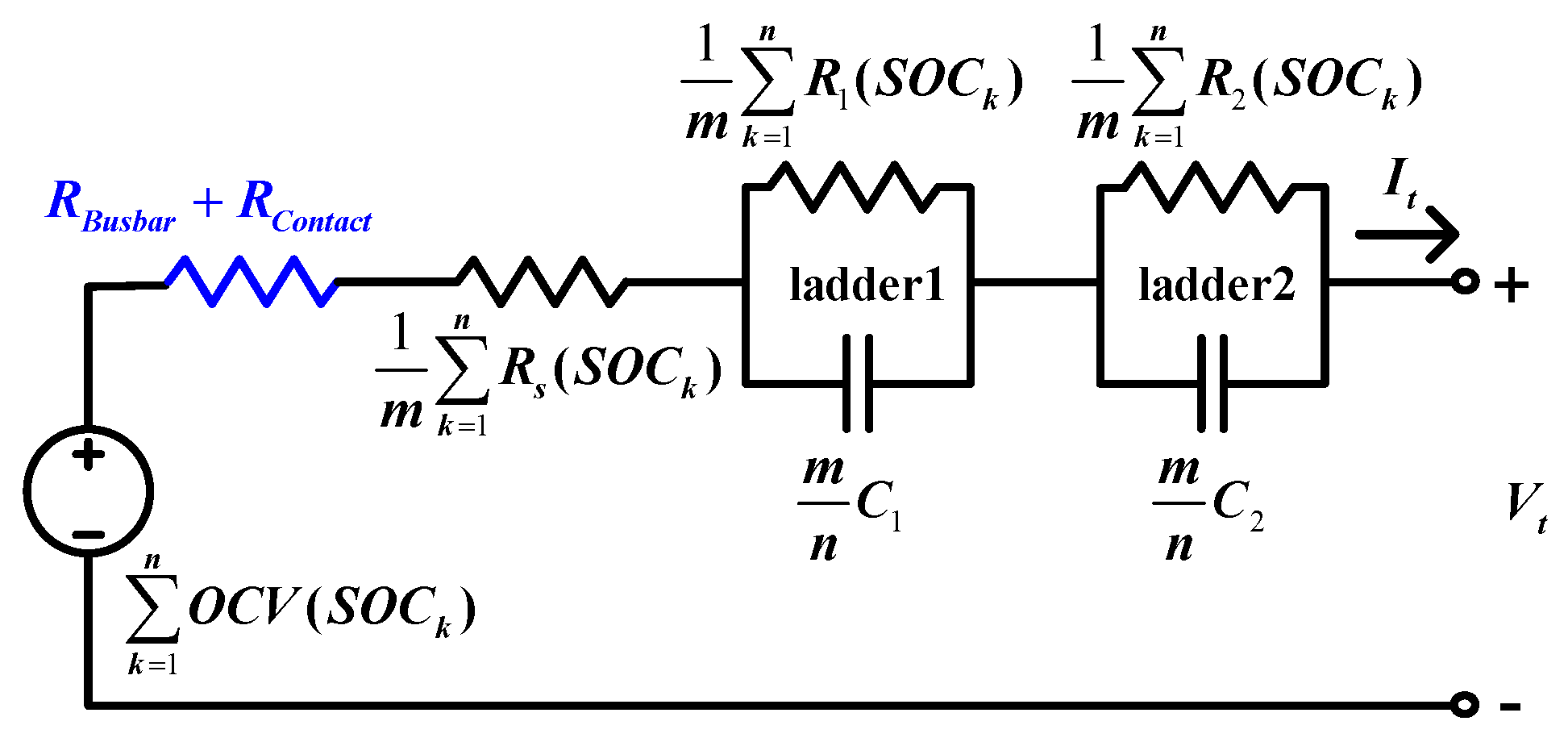
2. Proposed Battery Pack Modeling Method

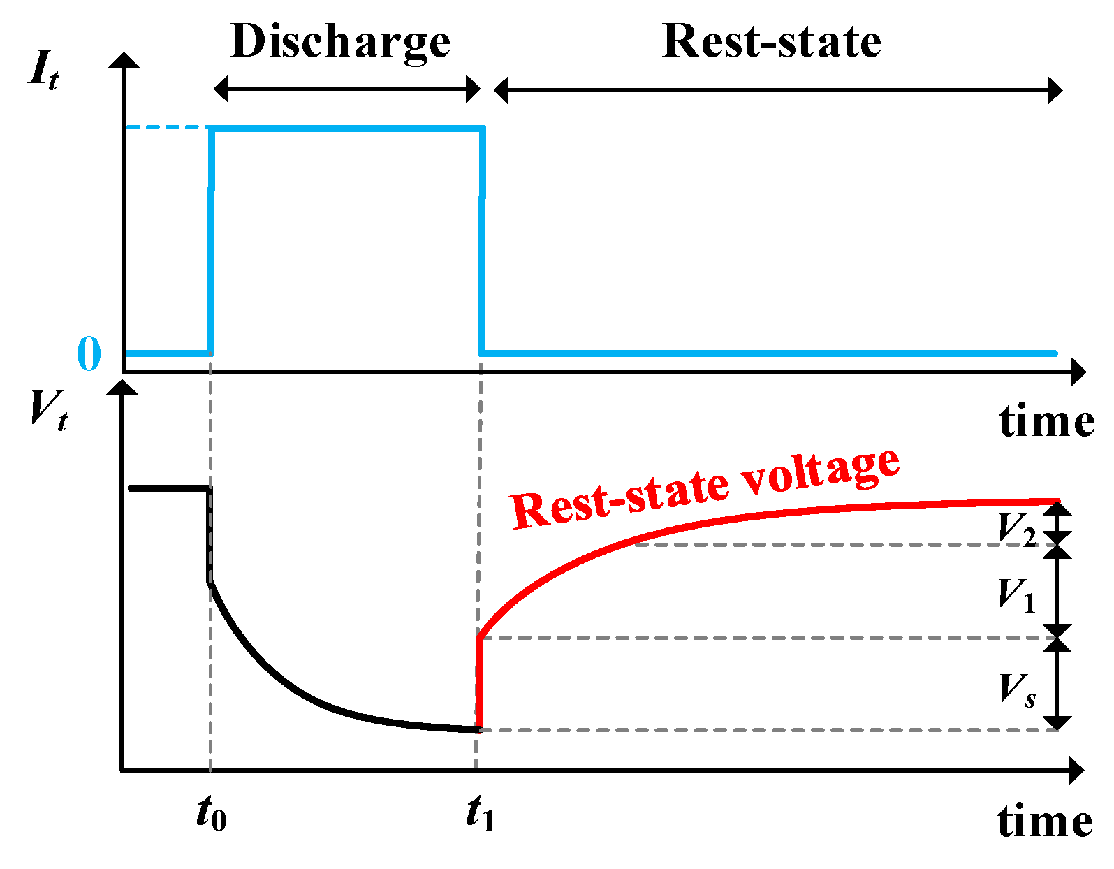
2.1. Battery Cell Modeling Process

A battery cell modeling technique, which is the basis of the proposed battery pack modeling technique, is addressed first in this subsection. Many of the battery models and the parameter identification methods were researched: The Rint model, the Randle model, the high order resistor-capacitor (RC) ladder model, and the general non-linear (GNL) model [13,14,15,16,17]. The battery modeling process can be divided into two parts: The first is for selecting the appropriate model structure, and the second is for determining the parameter values of the selected model structure. The more complex the model structure, the more accurate the battery characteristics can be simulated. Therefore, a trade-off between the model structure complexity and computational complexity must be considered. The 2nd RC ladder circuit model, illustrated in Figure 2, was used as the equivalent circuit model of the battery in this study. The model structure based on the 2nd RC-ladder circuit is used in most research because of its accuracy and low computational complexity [18,19]. In Figure 2, a series resistance (Rs) represents the immediate responses of the terminal voltage by current. The two RC networks, described as ladder1 and ladder2, represent the polarization voltages of the battery. The polarization voltage is a type of battery voltage caused by a polarization phenomenon associated with charge transfer at the electrode and electrolyte interface. The polarization voltage tends to change similarly to that of the sum of the exponential functions as shown in Figure 3. Therefore, ladder1 and ladder2 simulate the short-term and long-term components of the polarization voltage, respectively, with different time constants.
Determination of the parameter values for the selected model is dependent on experimental results of the battery cell. Generally, the extraction of parameters in the equivalent circuit model is based on the experiment which repeats charging or discharging with the pulse current and resting for 1 h as described in Figure 3. The terminal voltage of the equivalent circuit model during rest-state can be expressed as Equation (1), and Equation (1) is utilized to determine the parameter values of the battery model at a fixed state of charge (SOC).
V t = O C V + V s ( 1 u ( t 1 ) ) + V 1 e t t 1 τ 1 + V 2 e t t 1 τ 2 ,   where   t t 1
First, the open circuit voltage (OCV) was determined as the terminal voltage of the battery 1 h after the battery starts rest. Vs represents the instantaneous voltage drop by the change of the terminal current at t1. V1 and V2 indicates the voltage applied to ladder1 and ladder2, respectively, right after the battery starts rest-states, and τ1 and τ2 are the time constant of each ladder. V1, V2, τ1, and τ2 can be identified by fitting the measured terminal voltage during rest for 1 h to the sum of RC networks voltages. Rs, R1, and R2 were extracted by Ohm’s law and the relation to the time constant based on the measured and identified parameters as shown in Equation (2).
R s = V s I t , R 1 = V 1 I t , C 1 = τ 1 R 1 , R 2 = V 2 I t , C 2 = τ 2 R 2

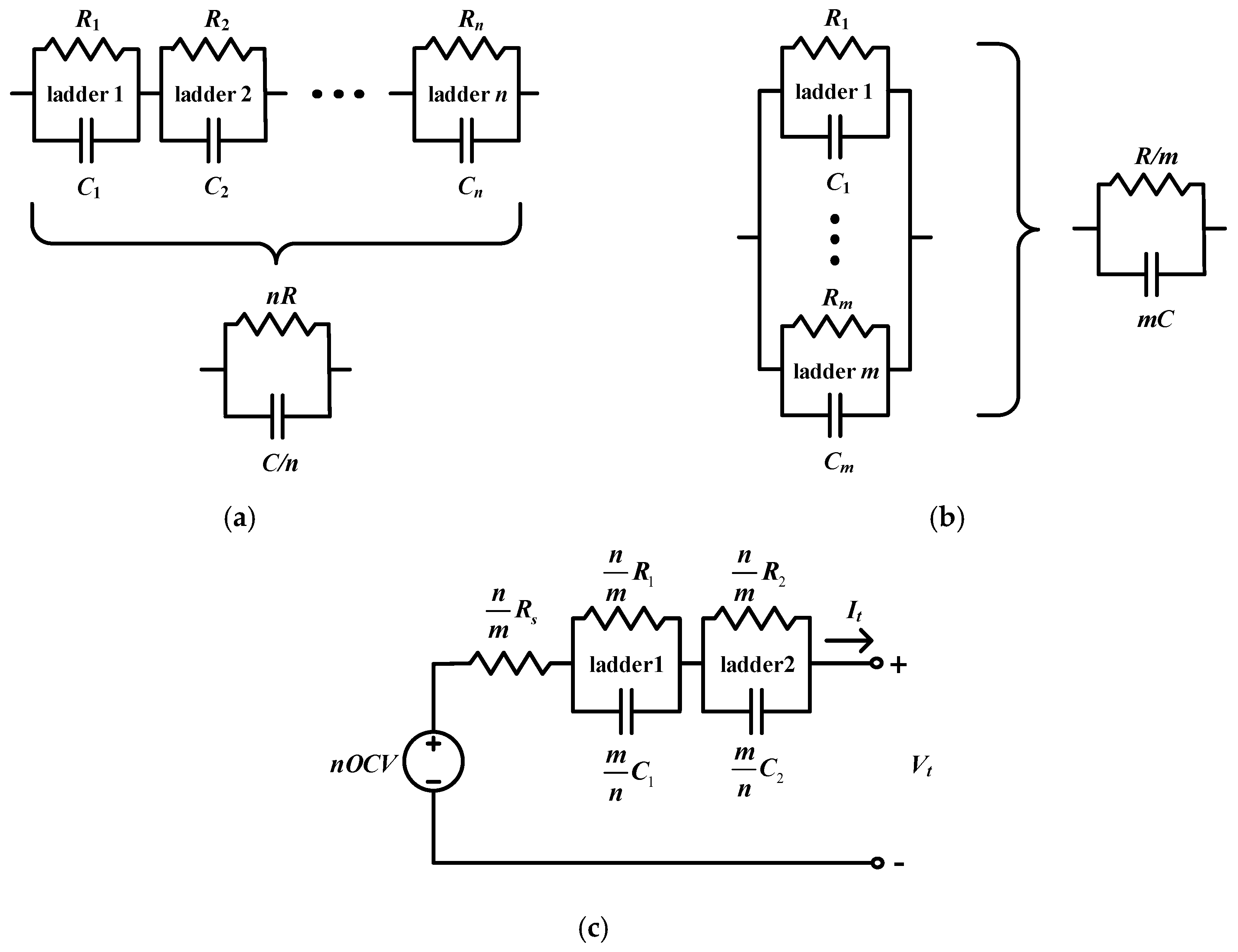
2.2. Battery Pack Modeling Under Ideal Assumption

A battery pack modeling can have a practical model structure on the basis with the assumption that intrinsic cell unbalances and the packaging elements do not affect the characteristics of the battery pack. In other words, it is possible to make a battery pack model, the sum of cell models based on the series-parallel configuration of cells in a pack, have a single 2nd RC-ladder model structure through the analysis below. If n-cells are connected in series, the total OCV and Rs components of n-cell models can be calculated by multiplying OCV and Rs by the number of cells. Moreover, the total R1 and C1, which are components of ladder1, are represented as a single R1, pack and C1, pack by
Z s e r i e s = n × 1 1 / R 1 + j ω C 1 = 1 1 / ( n R 1 ) + j ω C 1 / n = 1 1 / ( R 1 , p a c k ) + j ω C 1 , p a c k ( where ,   R 1 , p a c k = n R 1   a n d   C 1 , p a c k = C 1 n )
as shown in Figure 4a. If m-cells are connected in parallel, the total OCV is equal to a single cell OCV. Based on the virtual short concept, the total Rs can be represented as a single Rs by dividing by the number of cells. Similarly, as shown in Figure 4b, the total R1 and C1 are represented as a single R1, pack and C1, pack by
Z p a r a l l e l = 1 m × 1 1 / R 1 + j ω C 1 = 1 m / R 1 + j ω m C 1 = 1 1 / R 1 , p a c k + j ω C 1 , p a c k ( where , R 1 , p a c k = R 1 m a n d C 1 , p a c k = m C 1 )
Therefore, based on the assumption that there are no intrinsic cell unbalances and packaging elements, a battery pack model connected in n-series and m-parallel was built, as shown in Figure 4c.

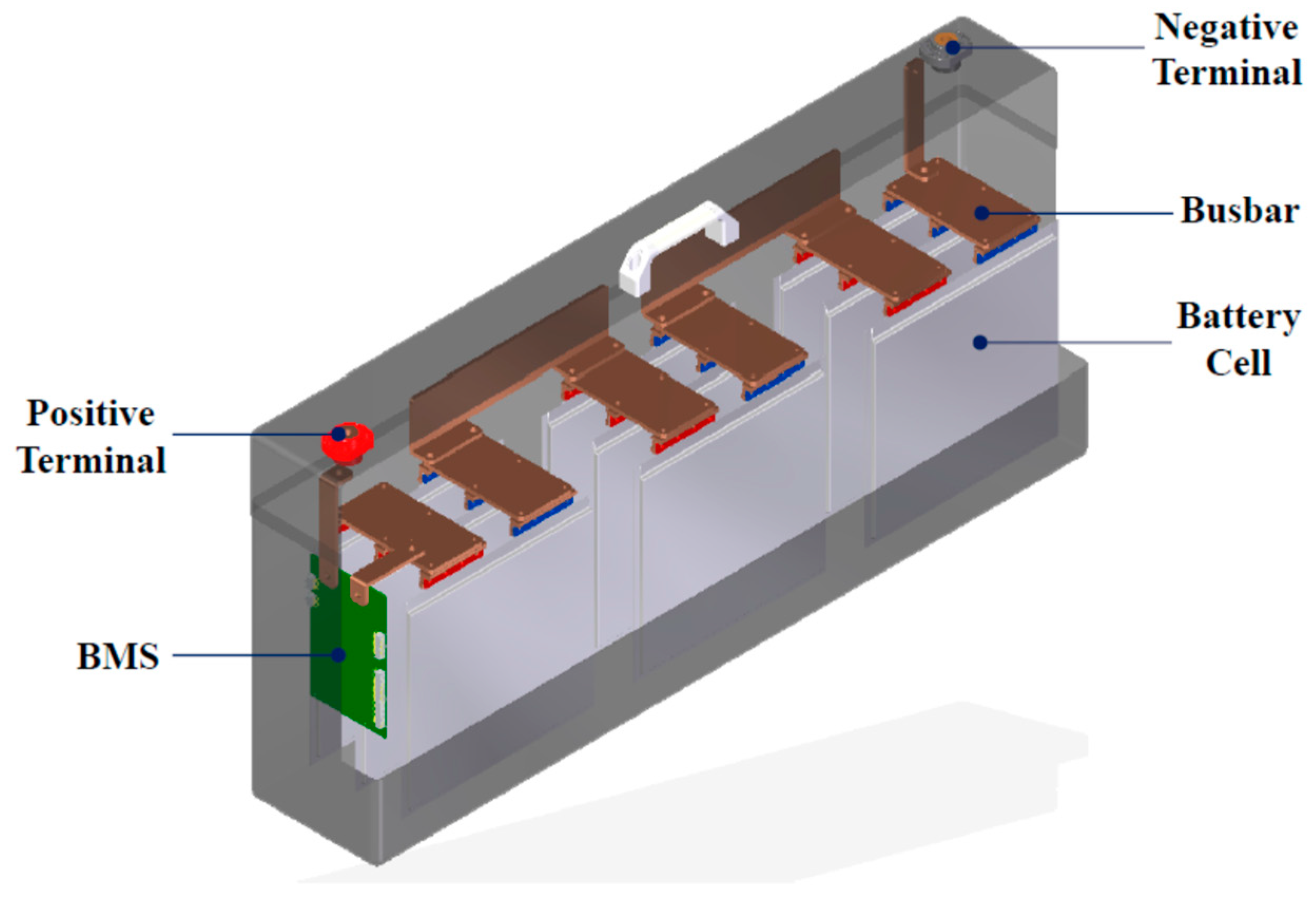
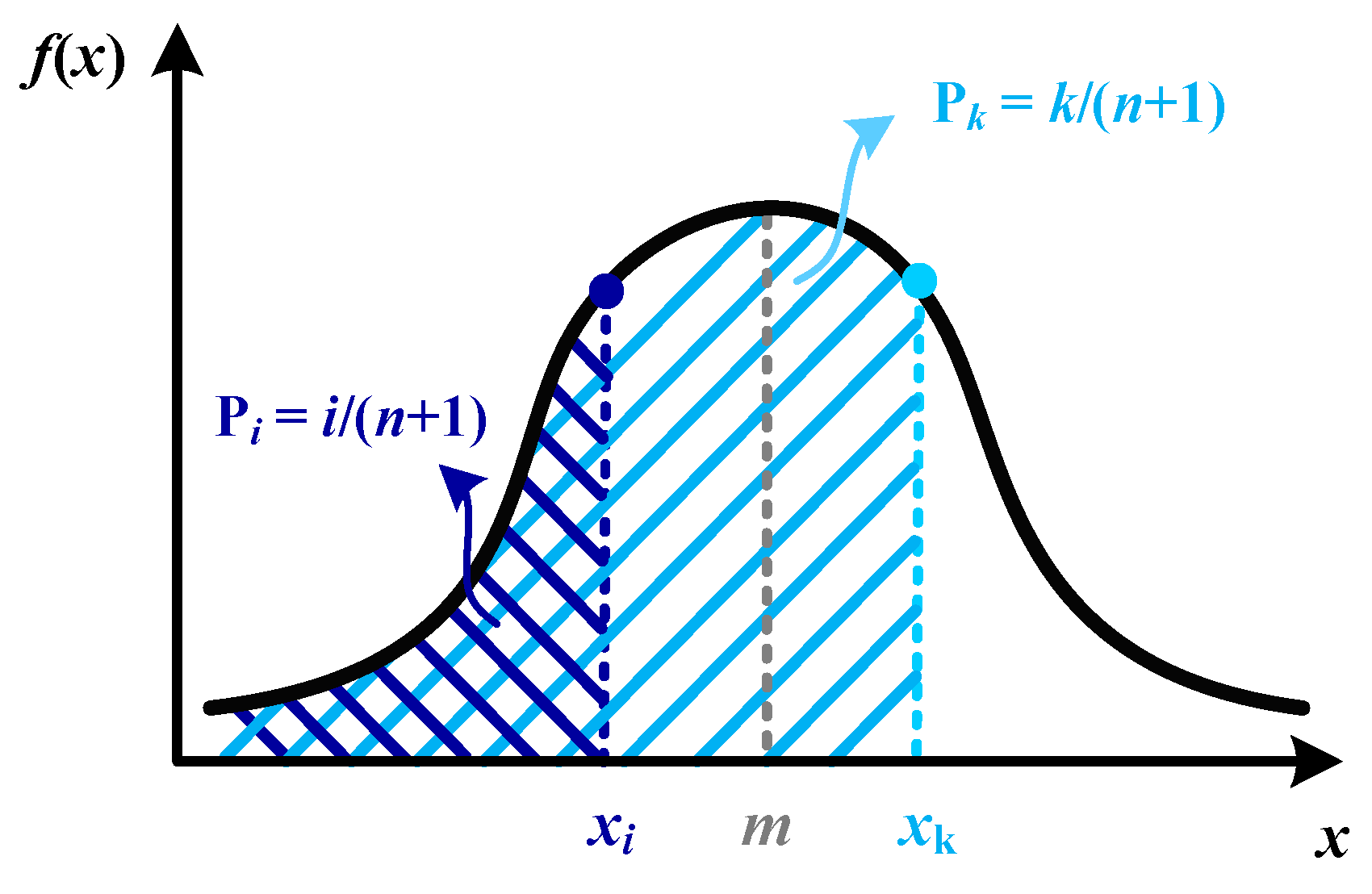
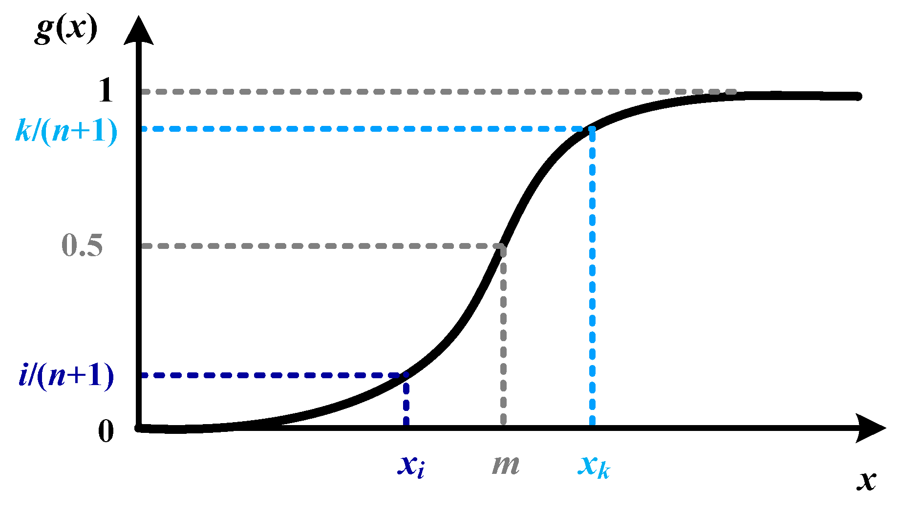
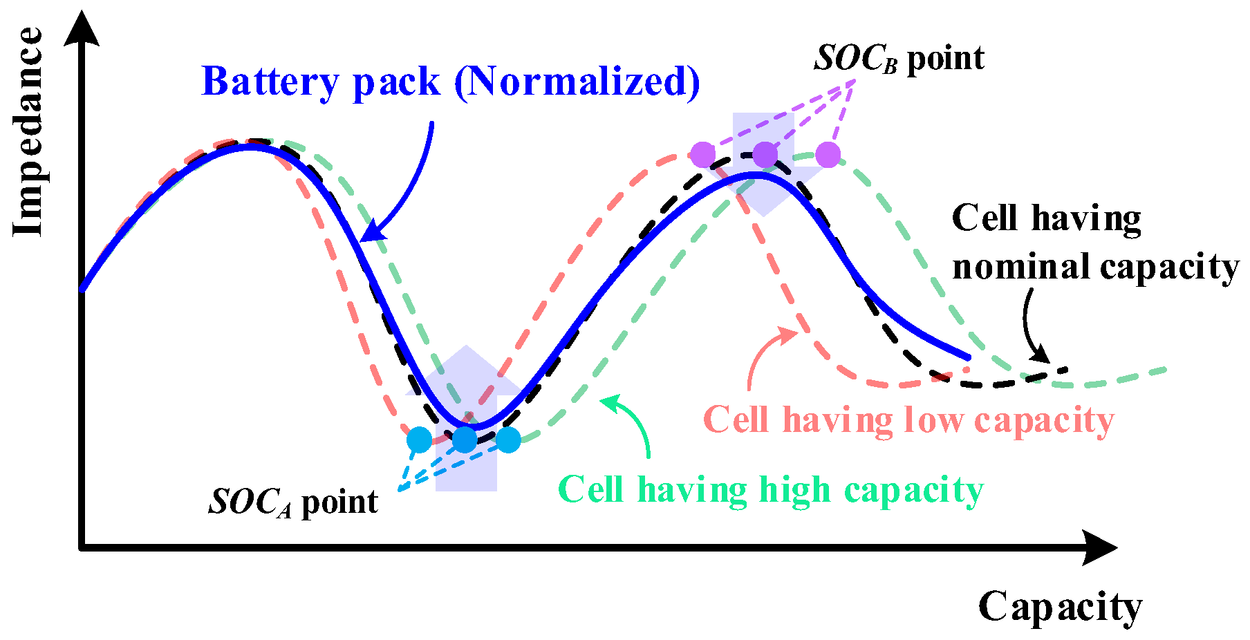
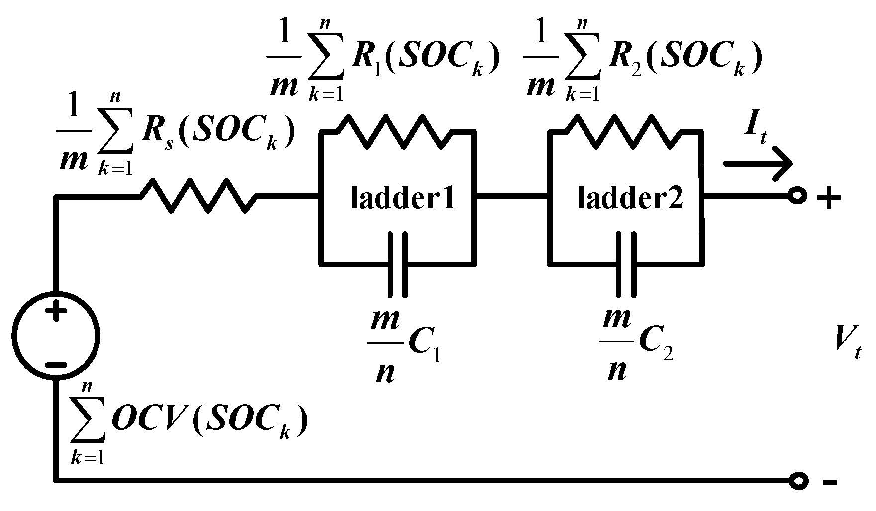
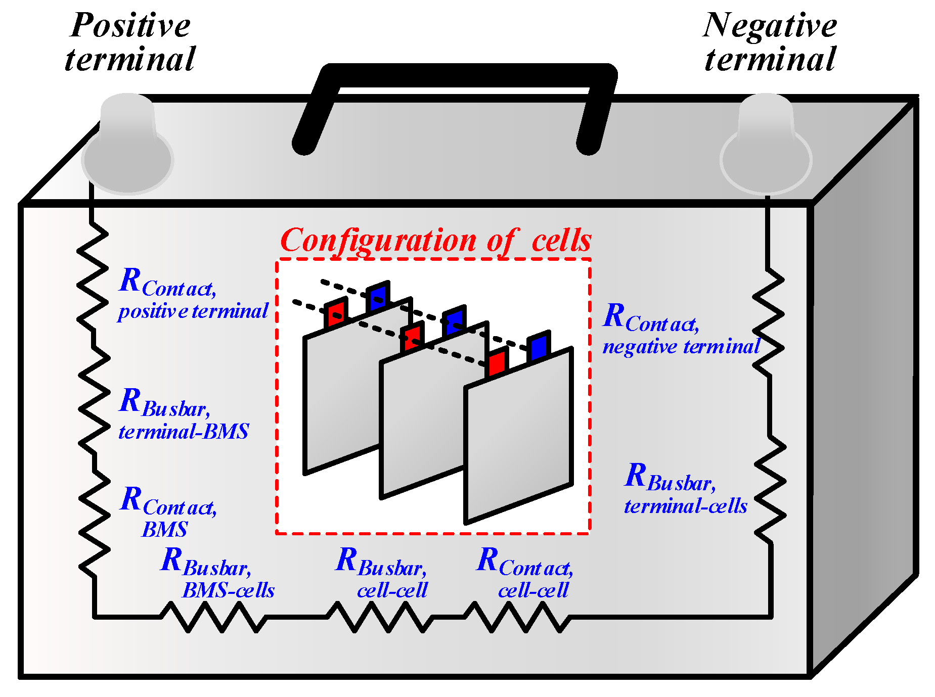
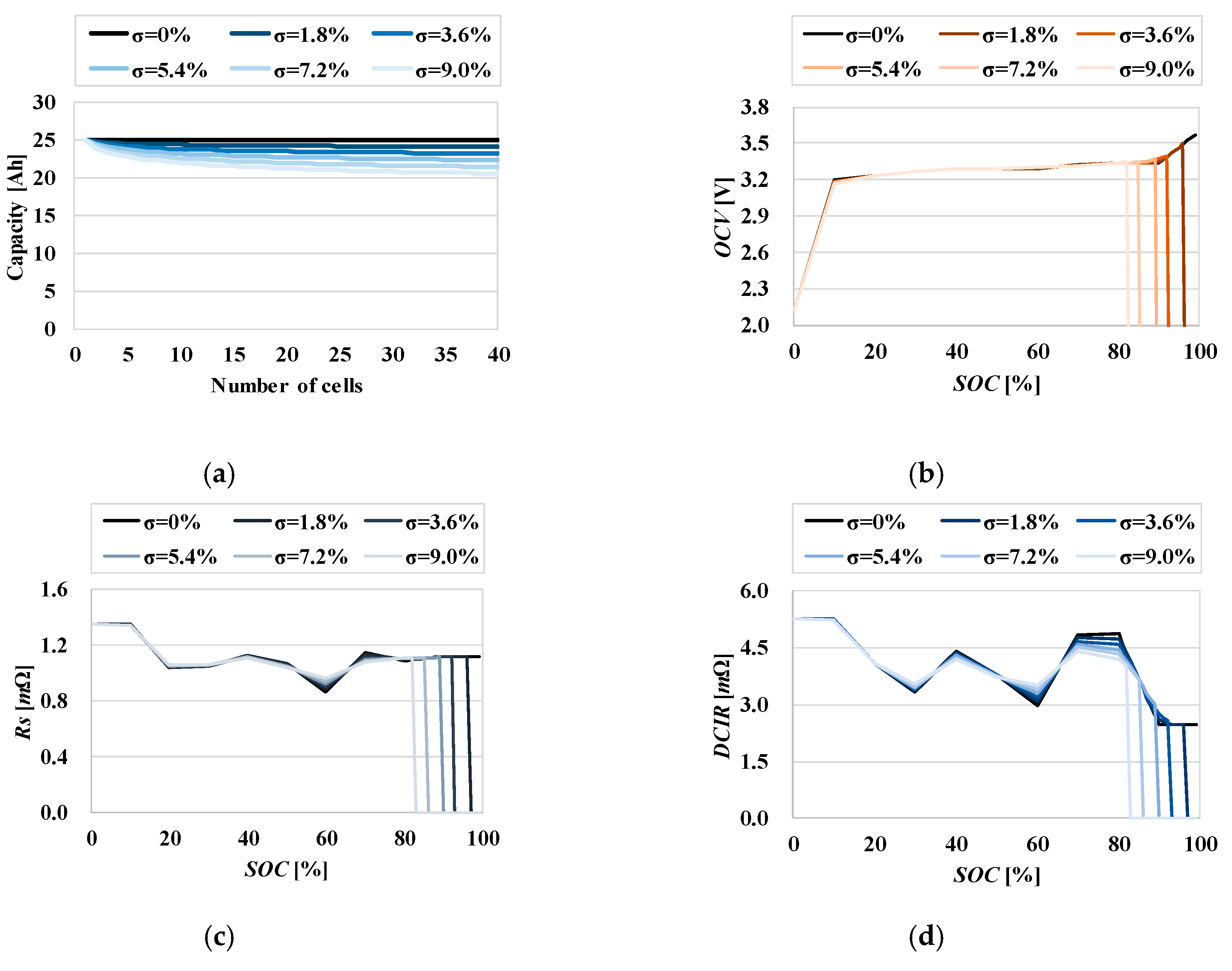
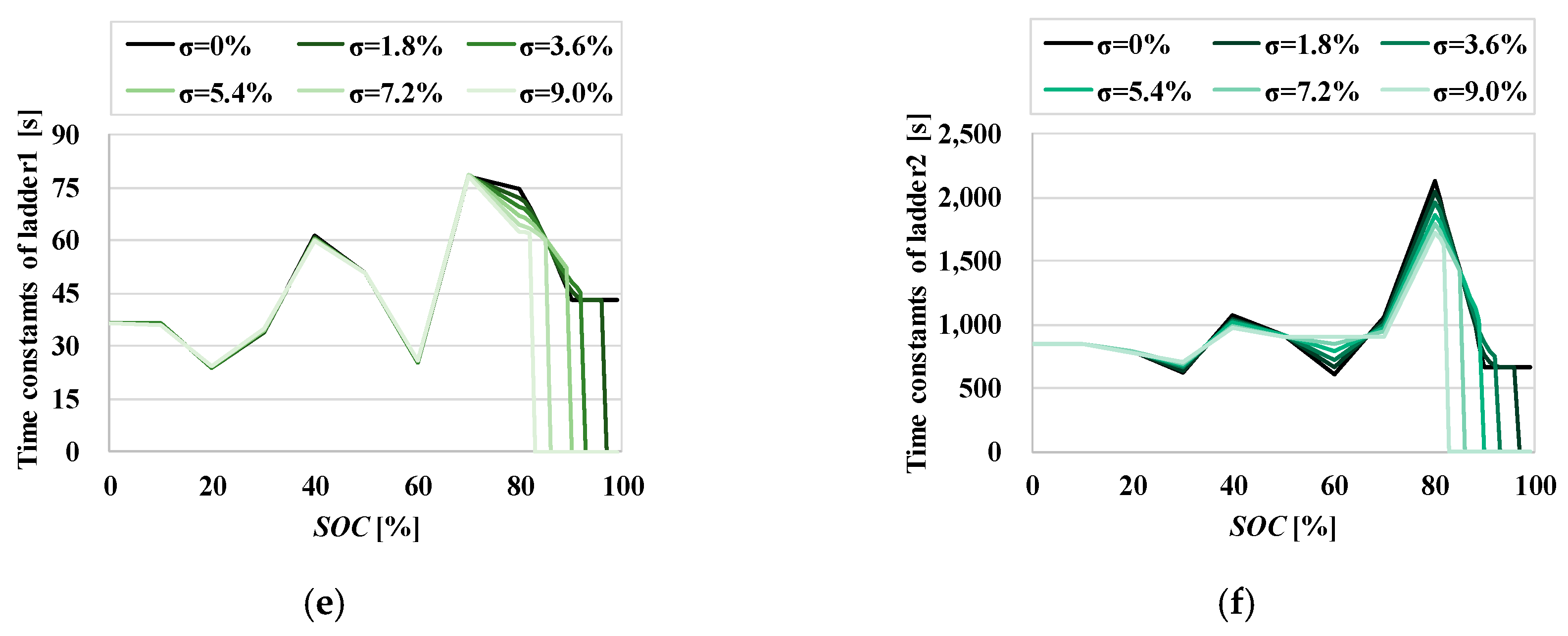
2.3. Analysis of Intrinsic Cell Unbalance and Packaging Elements for Proposed Battery Pack Modeling

Intrinsic cell unbalances cause cells in a pack to have different capacities, internal resistances, and SOCs. Therefore, the influence of intrinsic cell unbalances should be considered in the battery pack modeling process. It is assumed that the internal resistance of battery cell varies only by the SOC in order to quantify the influence of intrinsic cell unbalances.
When analyzing this intrinsic cell unbalances, the capacity of each cell is determined first. Thereafter, the SOC and internal resistance of each cell are calculated in order to determine the parameter values for the battery pack model. As shown in Figure 5 and Figure 6, if the capacity of each cell (x) follows the normal distribution with m and σ, which are the mean and standard deviation, respectively, the kth lowest capacity among n cells, xk, is calculated as follows:
g ( x ) = f ( x ) d x = x 1 σ 2 π e ( x m ) 2 2 σ 2 d x
and   x k = g 1 ( k n + 1 )
where f(x) is the normal distribution function and g(x) is the cumulative density function. Based on the capacities of all cells by Equation (6), SOCk, which is the SOC of a cell having the kth lowest capacity, can be expressed as
S O C k = a v e r a g e   c a p a c i t y k t h   l o w e s t   c a p a c i t y × S O C N = m x k × S O C N
where SOCN is the SOC of a cell with an average capacity.
The tendency of normalized impedances of the battery pack is described in Figure 7: Normalized impedances increase at the SOCA point where impedances of cells are concave up, and vice versa at the SOCB point. From this analysis, the internal resistance values of the pack model are calculated as
R p a c k = ( k = 1 n R ( S O C k ) ) / m
Finally, the battery pack model was built by considering the intrinsic cell unbalance, as shown in Figure 8. The resistances of the pack model are represented by Rs(SOCk), R1(SOCk), and R2(SOCk), which are functions of SOC of each cells.
The available capacity of a battery pack that only has a series connection of n cells is calculated as
P a c k C a p a c i t y s e r i e s = x 1
This is because in a series cell connection, the total capacity is limited by the minimum capacity, and xk is defined above as the kth lowest capacity among n cells. Conversely, the capacity of a battery pack that only has a parallel connection of m cells, is calculated as
P a c k C a p a c i t y p a r a l l e l = k = 1 m x k
which means that the pack capacity is equal to the total sum of cell capacities [20].
The packaging elements should be analyzed in the proposed modeling process as the influence of the packaging components increases with the number of cells in the pack. Connections among cells, between the cell and positive/negative terminals of the pack, and between the cell and BMS, result in contact resistance—in addition to resistance in busbar. As shown in Figure 9, the resistance of the packaging elements can be expressed as the sum of the busbar resistance, RBusbar, and contact resistance, RContact. These components were added to the proposed model as a lumped resistance, as shown in Figure 10.

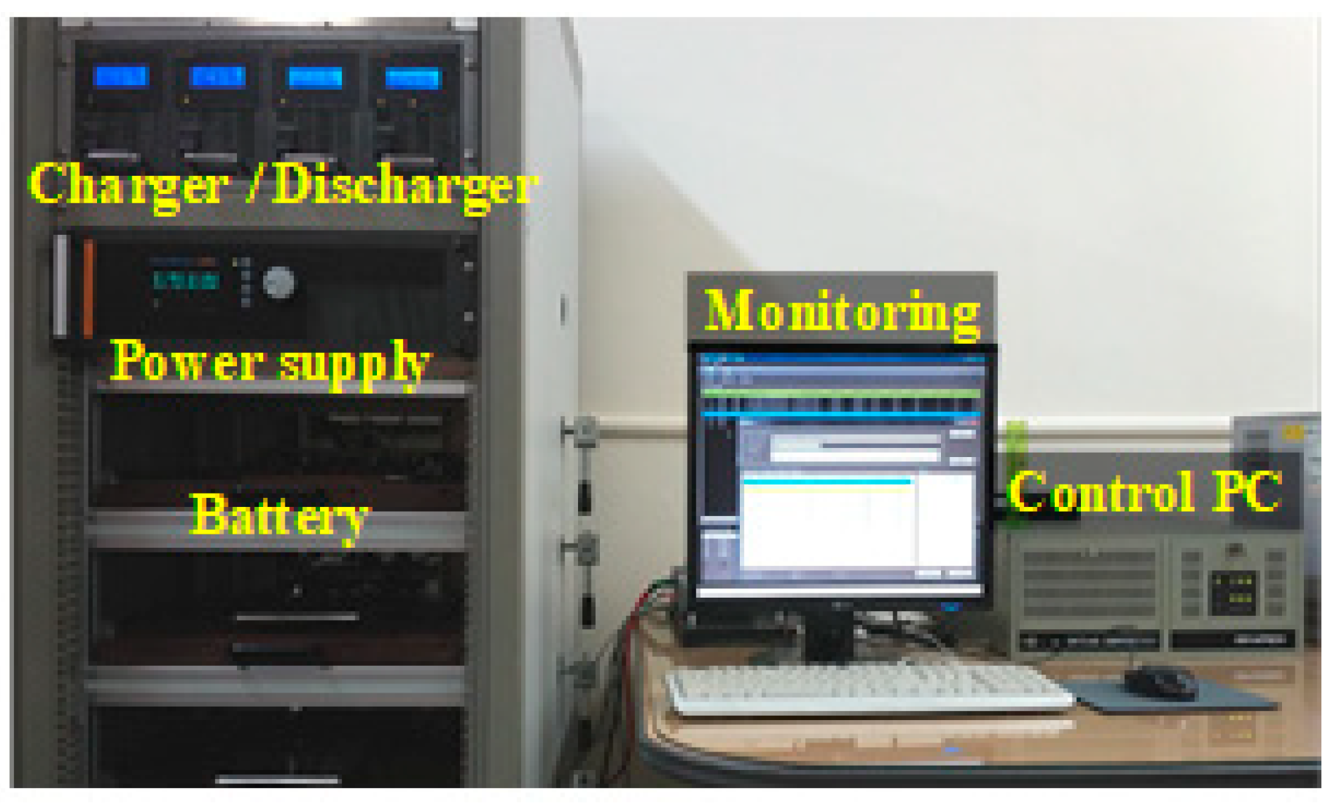
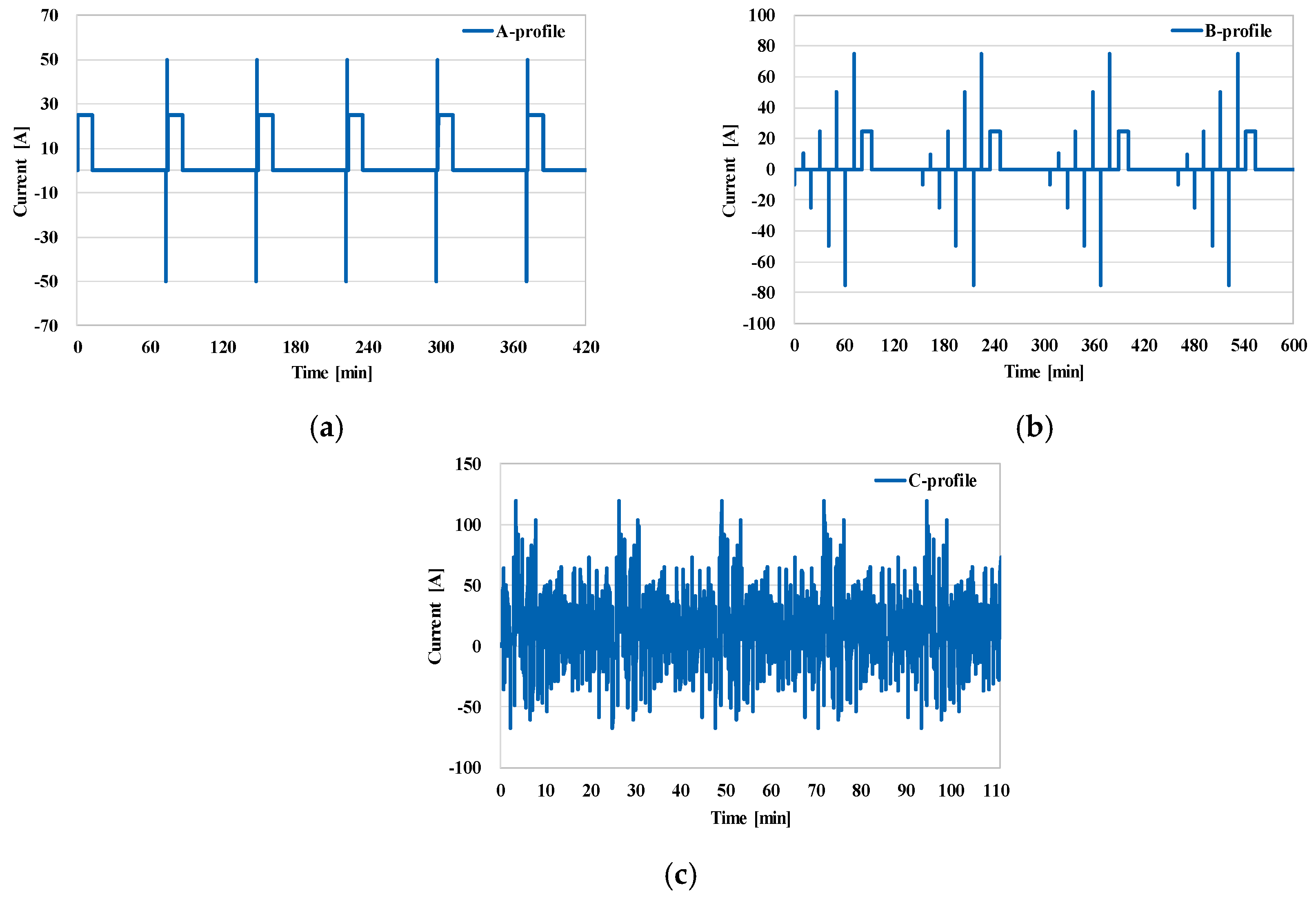
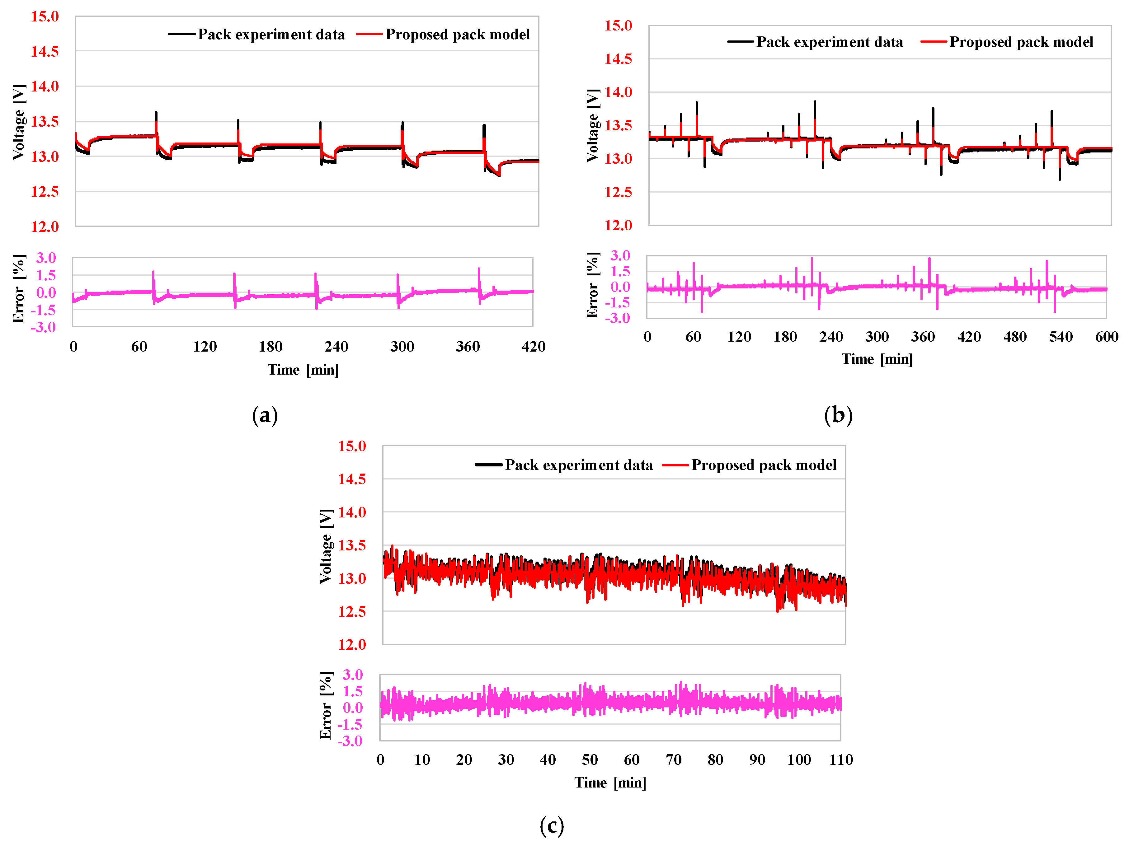
3. Simulation and Experimental Verification

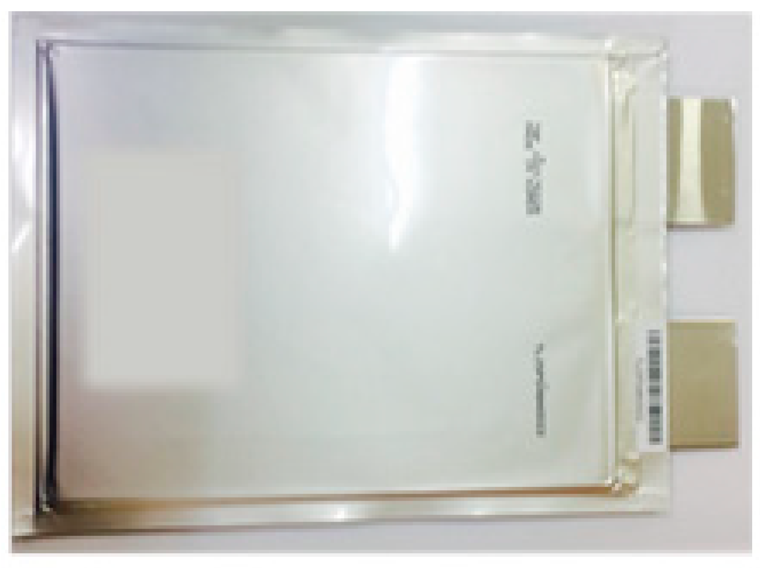
3.1. Construction of Proposed Pack Model

The proposed battery pack modeling required preliminary works, which is cell modeling. The experiment apparatus, presented in Figure 11, and a LiFePO4 (LFP) battery cell, shown in Figure 12, were set up to extract the parameter values that fit the 2nd RC-ladder model structure. The parameters of the cell model, shown in Figure 13, were extracted with a SOC interval of 10% through the parameter extraction method described in Section 2.1. As shown in Figure 13a, OCV-SOC curve changed dramatically as SOC dropped to 0% and rose to 100%, which are the characteristics of a LFP battery [21]. The time constants of ladder1 was much shorter than ladder2, because ladder1 described a shorter-term component of the polarization voltage than ladder2.
The parameter values of the proposed pack model that account for intrinsic cell unbalances can be obtained through the cell experimental results and analysis described in Section 2.3. The parameter, described in Figure 14, was normalized according to the number of cells connected in series and parallel. In terms of the number of cells connected in series and standard deviation of cell capacities, the capacity of the battery pack is presented in Figure 14a. The capacity of the battery pack decreased as the number of cells and standard deviation increased because the minimum cell capacity of those in the pack governed its whole capacity. As shown in Figure 14b, the battery pack OCV decreased as the number of cells connected in series and the standard deviation increased because of its BMS protection.
In Figure 14b–f, points indicated by vertical lines are locations where the circuit is cut off by the BMS to protect the battery pack from overcharging. The charging or discharging losses of the pack are directly proportional to internal resistances, such as Rs and DCIR. Consequently, power losses can be estimated by utilizing the resistance of the proposed pack model, as shown in Figure 14c,d.
Additionally, the diffusion and polarization characteristics of the battery pack can be predicted by the RC ladder parameter values shown in Figure 14e,f. Therefore, the optimal design for the pack at the cell-level can be achieved by considering capacity first, OCV variations, and thereafter, considering power losses and transient responses in the major operating area of the SOC.
An SLI battery pack—mainly used in automobiles—is selected to verify the validity of the proposed modeling method, as shown in Figure 15. The specification of the SLI battery is listed in Table 1. The standard deviation, σ, was assumed to be 1.8%, which is generally accepted as the capacity deviation in [22]. Moreover, the effects of the packaging elements were considered according to the design specification listed in Table 2. The busbar and contact resistances were calculated as 0.45 and 1.2 mΩ, respectively.

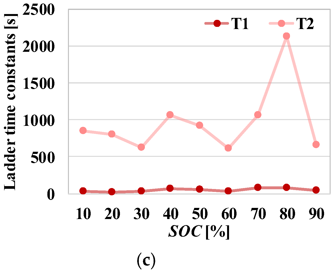
3.2. Evaluation of Proposed Pack Model

Experiments and simulations were conducted by applying three current profiles: A-profile is the HPPC test profile, which is used for estimating battery power; B-profile is used to extract the DCIR of the battery; and C-profile is the dynamic current profile, which is repeated five times for approximately 2 h [23]. The three current profiles, shown in Figure 16, were used for verifying the proposed battery pack model. The terminal voltages and error rates of the SLI battery pack and proposed battery pack model are shown in Figure 17.
The mean absolute percentage error (MAPE) and root mean square error (RMSE), which are calculated as
MAPE = 100 n k = 1 n | V r e f V model V r e f |
and   RMSE = 1 n k = 1 n ( V r e f V model ) 2
are summarized with the maximum terminal voltage error in Table 3. In the three test profiles, the maximum error rates, MAPE and RMSE did not exceed 3%, 0.5%, and 0.07 V, respectively. Based on the experimental and simulation results, the proposed pack model seems to have high reliability in accuracy under various current profiles.

4. Conclusions

In this paper, an innovative battery pack modeling method was proposed. In contrast with existing modeling methods, this method enabled the modeling of the battery pack, using only the cell parameters without additional experiments for the battery pack modeling. Since the dynamic characteristics of the battery pack can be predictable through the proposed pack model only using the cell parameters, it is possible to contribute to the design of the battery pack optimized for the application, such as electrical vehicles, energy storage systems, among others. Moreover, the proposed model has high reliability in accuracy under various current profiles by considering intrinsic cell unbalances and packaging elements. Based on the MAPE, RMSE, and maximum error for the A-, B-, and C-profiles, it is evident that the proposed pack model possesses high accuracy, which is expected to enhance the accuracy of state estimation algorithms in BMS.

Author Contributions

Conceptualization, S.-T.K. and J.L.; Data curation, S.-T.K. and J.-H.A.; Formal analysis, S.-T.K.; Investigation, S.-T.K.; Project administration, B.K.L.; Software, J.L.; Supervision, B.K.L.; Validation, S.-T.K.; Visualization, J.L.; Writing–original draft, J.-H.A. and B.K.L.; Writing–review & editing, S.-T.K. and B.K.L.

Funding

This work was supported by “Human Resources Program in Energy Technology” of the Korea Institute of Energy Technology Evaluation and Planning (KETEP), granted financial resource from the Ministry of Trade, Industry & Energy, Republic of Korea (No. 20184030202190). This work was supported by the Korea Institute of Energy Technology Evaluation and Planning (KETEP) and the Ministry of Trade, Industry & Energy (MOTIE) of the Republic of Korea (No. 20168530050030).

Conflicts of Interest

The authors declare no conflict of interest.

References

  1. Zhang, W.; Shi, W.; Ma, Z. Adaptive unscented Kalman filter based state of energy and power capability estimation approach for lithium-ion battery. J. Power Sources 2015, 289, 50–62. [Google Scholar] [CrossRef]
  2. Lu, L.; Han, X.; Li, J.; Hua, J.; Ouyang, M. A review on the key issues for lithium-ion battery management in electric vehicles. J. Power Sources 2013, 226, 272–288. [Google Scholar] [CrossRef]
  3. Plett, G.L. High-performance battery-pack power estimation using a dynamic cell model. IEEE Trans. Veh. Technol. 2004, 53, 1586–1593. [Google Scholar] [CrossRef]
  4. Schmidt, A.P.; Bitzer, M.; Imre, A.W.; Guzzella, L. Experiment-driven electrochemical modeling and systematic parameterization for a lithium-ion battery cell. J. Power Sources 2010, 195, 5071–5080. [Google Scholar] [CrossRef]
  5. Peterson, S.B.; Apt, J.; Whitacre, J.F. Lithium-ion battery cell degradation resulting from realistic vehicle and vehicle-to-grid utilization. J. Power Sources 2010, 195, 2385–2392. [Google Scholar] [CrossRef]
  6. Kim, T.; Qiao, W. A hybrid battery model capable of capturing dynamic circuit characteristics and nonlinear capacity effects. IEEE Trans. Energy Convers. 2011, 26, 1172–1180. [Google Scholar] [CrossRef]
  7. Li, J.; Mazzola, M.S. Accurate battery pack modeling for automotive applications. J. Power Sources 2013, 237, 215–228. [Google Scholar] [CrossRef]
  8. Watrin, N.; Bouquain, D.; Blunier, B.; Miraoui, A. Multiphysical lithium-based battery pack modeling for simulation purposes. In Proceedings of the 2011 IEEE Vehicle Power and Propulsion Conference, Chicago, IL, USA, 6–9 September 2011. [Google Scholar]
  9. Castano, S.; Gauchia, L.; Voncila, E.; Sanz, J. Dynamical modeling procedure of a Li-ion battery pack suitable for real-time applications. Energy Convers. Manag. 2015, 92, 396–405. [Google Scholar] [CrossRef]
  10. Andre, D.; Appel, C.; Soczka-Guth, T.; Sauer, D.U. Advanced mathematical methods of SOC and SOH estimation for lithium-ion batteries. J. Power Sources 2013, 224, 20–27. [Google Scholar] [CrossRef]
  11. Gholizadeh, M.; Salmasi, F.R. Estimation of state of charge, unknown nonlinearities, and state of health of a lithium-ion battery based on a comprehensive unobservable model. IEEE Trans. Ind. Electron. 2013, 61, 1335–1344. [Google Scholar] [CrossRef]
  12. Sen, C.; Kar, N.C. Battery pack modeling for the analysis of battery management system of a hybrid electric vehicle. In Proceedings of the 2009 IEEE Vehicle Power and Propulsion Conference, Dearborn, MI, USA, 7–11 September 2009; pp. 1–5. [Google Scholar]
  13. Sitterly, M.; Wang, L.Y.; Yin, G.G.; Wang, C. Enhanced identification of battery models for real-time battery management. IEEE Trans. Sustain. Energy 2011, 2, 300–308. [Google Scholar] [CrossRef]
  14. Wijewardana, S.; Vepa, R.; Shaheed, M.H. Dynamic battery cell model and state of charge estimation. J. Power Sources 2016, 308, 109–120. [Google Scholar] [CrossRef]
  15. Wei, Z.; Zhao, J.; Ji, D.; Tseng, K.J. A multi-timescale estimator for battery state of charge and capacity dual estimation based on an online identified model. Appl. Energy 2017, 204, 1264–1274. [Google Scholar] [CrossRef]
  16. Yang, J.; Xia, B.; Shang, Y.; Huang, W.; Mi, C.C. Adaptive state-of-charge estimation based on a split battery model for electric vehicle applications. IEEE Trans. Veh. Technol. 2017, 66, 10889–10898. [Google Scholar] [CrossRef]
  17. Meng, J.; Luo, G.; Ricco, M.; Swierczynski, M.; Stroe, D.; Teodorescu, R. Overview of lithium-ion battery modeling methods for state-of-charge estimation in electrical vehicles. Appl. Sci. 2018, 8, 659. [Google Scholar] [CrossRef]
  18. Zhang, H.; Mo-Yuen, C. Comprehensive dynamic battery modeling for PHEV applications. In Proceedings of the IEEE PES General Meeting, Providence, RI, USA, 25–29 July 2010. [Google Scholar]
  19. Hu, X.; Li, S.; Peng, H. A comparative study of equivalent circuit models for Li-ion batteries. J. Power Sources 2012, 198, 359–367. [Google Scholar] [CrossRef]
  20. Zhong, L.; Zhang, C.; He, Y.; Chen, Z. A method for the estimation of the battery pack state of charge based on in-pack cells uniformity analysis. Appl. Energy 2014, 113, 558–564. [Google Scholar] [CrossRef]
  21. Lin, C.; Yu, Q.; Xiong, R.; Wang, L.Y. A study on the impact of open circuit voltage tests on state of charge estimation for lithium-ion batteries. Appl. Energy 2017, 205, 892–902. [Google Scholar] [CrossRef]
  22. Dubarry, M.; Nicolas, V.; Yann, L.B. From single cell model to battery pack simulation for Li-ion batteries. J. Power Sour. 2009, 186, 500–507. [Google Scholar] [CrossRef]
  23. Kim, J.H.; Lee, S.J.; Lee, J.M.; Cho, B.H. A new direct current internal resistance and state of charge relationship for the Li-ion battery pulse power estimation. In Proceedings of the 2007 7th International Conference on Power Electronics, Bangkok, Thailand, 27–30 November 2007; pp. 1173–1178. [Google Scholar]
Figure 1. Configuration of battery pack.
Energies 12 00356 g001
Figure 2. 2nd resistor-capacitor (RC) ladder model structure.
Energies 12 00356 g002
Figure 3. Profile for battery modeling.
Energies 12 00356 g003
Figure 4. Battery pack modeling in the ideal case. (a) Analysis of RC ladders connected in series; (b) Analysis of RC ladders connected in parallel; (c) Pack model in the ideal case (n-series and m-parallel).
Energies 12 00356 g004
Figure 5. Normal distribution of cell capacity.
Energies 12 00356 g005
Figure 6. Cumulative density function of cell capacity.
Energies 12 00356 g006
Figure 7. Tendency of internal impedance of pack.
Energies 12 00356 g007
Figure 8. Pack model built by considering cell unbalance (n-series and m-parallel).
Energies 12 00356 g008
Figure 9. Two types of additional resistance components.
Energies 12 00356 g009
Figure 10. Proposed battery pack model including the lumped resistance of RBusbar and RContact.
Energies 12 00356 g010
Figure 11. Experimental apparatus.
Energies 12 00356 g011
Figure 12. A 25 Ah LiFePO4 battery cell.
Energies 12 00356 g012
Figure 13. Parameters of battery cell based on experimental results. (a) OCV; (b) Resistances; (c) Time constants of RC ladders.
Energies 12 00356 g013aEnergies 12 00356 g013b
Figure 14. Normalized parameters of proposed model of battery pack. (a) Capacity; (b) OCV; (c) Rs; (d) Direct current internal resistance (DCIR); (e) Time constants of ladder1; (f) Time constants of ladder2.
Energies 12 00356 g014aEnergies 12 00356 g014b
Figure 15. Starting–lighting–ignition (SLI) battery pack.
Energies 12 00356 g015
Figure 16. Three current profiles for verification of proposed model. (a) A-profile; (b) B-profile; (c) C-profile.
Energies 12 00356 g016
Figure 17. Verification results of proposed model. (a) Test results in A-profile; (b) Test results in B-profile; (c) Test results in C-profile.
Energies 12 00356 g017
Table 1. Specification of the SLI battery pack.
TypeLiFePO4 (LFP)
Capacity50 Ah
Operating voltage8.0 V–14.4 V
Configuration2-parallel and 4-series
Table 2. Design specification of busbar.
MaterialLengthCross-Sectional Area
Copper1084 mm40 mm2
Table 3. Error rates of proposed pack model.
MaterialLengthCross-Sectional Area
Copper1084 mm40 mm2

