Article

Torque Ripple Optimization of a Novel Cylindrical Arc Permanent Magnet Synchronous Motor Used in a Large Telescope

School of Electrical Engineering, Southeast University, Nanjing 210096, China
*
Author to whom correspondence should be addressed.
Energies 2019, 12(3), 362; https://doi.org/10.3390/en12030362
Submission received: 10 January 2019 / Revised: 21 January 2019 / Accepted: 21 January 2019 / Published: 24 January 2019
(This article belongs to the Section F: Electrical Engineering)

Abstract

:
This paper proposes the use of a novel cylindrical arc permanent magnet synchronous motor (CAPMSM) in a large telescope, which requires high positioning accuracy and low torque ripple. A 2D finite element method was used to analyze the cogging torque of the CAPMSM. The CAPMSM can be an alternative for a rotating motor to realize direct drive. A new method is proposed to separate the cogging torque, Tcog, into the torque, Tslot, generated by the slotted effect and the end torque, Tend, generated by the end effect. The average torque and the torque ripple are optimized considering stator center angle, the angle between two adjacent stators and the unequal thickness of a Halbach permanent magnet. The torque ripple decreased from 31.73% to 1.17%, which can satisfy the requirement of tracking accuracy for large telescopes.

1. Introduction

A traditional rotary motor integrating gear box is used to achieve limited angular motion, which causes issues such as taking up a lot of space, leading to low transmission accuracy. Therefore, an arc permanent magnet synchronous machine (APMSM) is proposed to achieve the direct drive for finite angular motion [1]. However, the application of an APMSM is subjected to reluctance force, control precision, and speed response issues. The reluctance force is generated by the slotted effect and the end effect. Chu et al. investigated the influence of skewing on the reduction of the slotted effect [2]. The slotted torque and cogging torque are reduced by the variations of permanent magnet (PM) arrangement [3,4]. Fractional slot concentrated winding is an effective way to reduce torque ripple [5,6]. Furthermore, the slotted effect can be decreased by adjusting pole pitch, optimizing magnet-pole shape and, adopting closed stator slots, etc. [7,8,9]. An auxiliary poles optimal design is adopted to reduce the end effect reluctance force of permanent magnet linear synchronous motor (PMLSM), which is caused by a finite stator length [10]. In Reference [11], the influence of the stator length on the reluctance force was analyzed, which showed that the reluctance force can be greatly decreased by optimizing the stator length. A kind of compensation winding was proposed to decrease the reluctance force in Reference [12]. Ho et al. proposed a Halbach PM array to increase in thrust force density and reduce cogging force [13]. Wang et al. showed that the dual-stator PM vernier machine with flux-reversal PM arrangement brings high torque production with low cogging torque [14]. Jin et al. proposed a combined maximum cogging torque (MCT) optimization method to optimize the MCT of surface-mounted PM machines with relatively low computer resources [15]. Du et al. proposed a new interior PM machine design, which can increase PM utilization ratio and reduce the torque ripple [16]. Liu et al. proposed a method of reducing total torque ripple by magnets shifting [17]. In Reference [18], a PM tubular linear generator with a Halbach PM arrangement was proposed to weaken the reluctance force. In Reference [19], it was shown that a ∇ + U shape topology of rotor has the least total harmonic distortion (THD) of air-gap flux density and cogging torque. Zou et al. proposed PM arc shaping to reduce cogging torque and torque ripple [20].
This paper proposes a novel cylindrical arc permanent magnet synchronous motor (CAPMSM) with three stators. The detent force of the proposed CAPMSM is optimized considering stator central angle, angle between two adjacent stators, unequal thickness of Halbach PM, and the central angle of slot pitch. The optimal stator center angle is obtained by finite element verification of the left and right end forces. The angle between two adjacent stators is optimized by Fourier analysis of the end torque of three stators. A sinusoidal distribution of air gap flux density is improved by adopting unequal thickness of Halbach PMs. The slot pitch is changed to improve the period of slot cogging force. In addition, a new method is proposed to separate the cogging torque, Tcog, into the torque, Tslot, generated by the slotted effect and the end torque, Tend, generated by the end effect for CAPMSM.

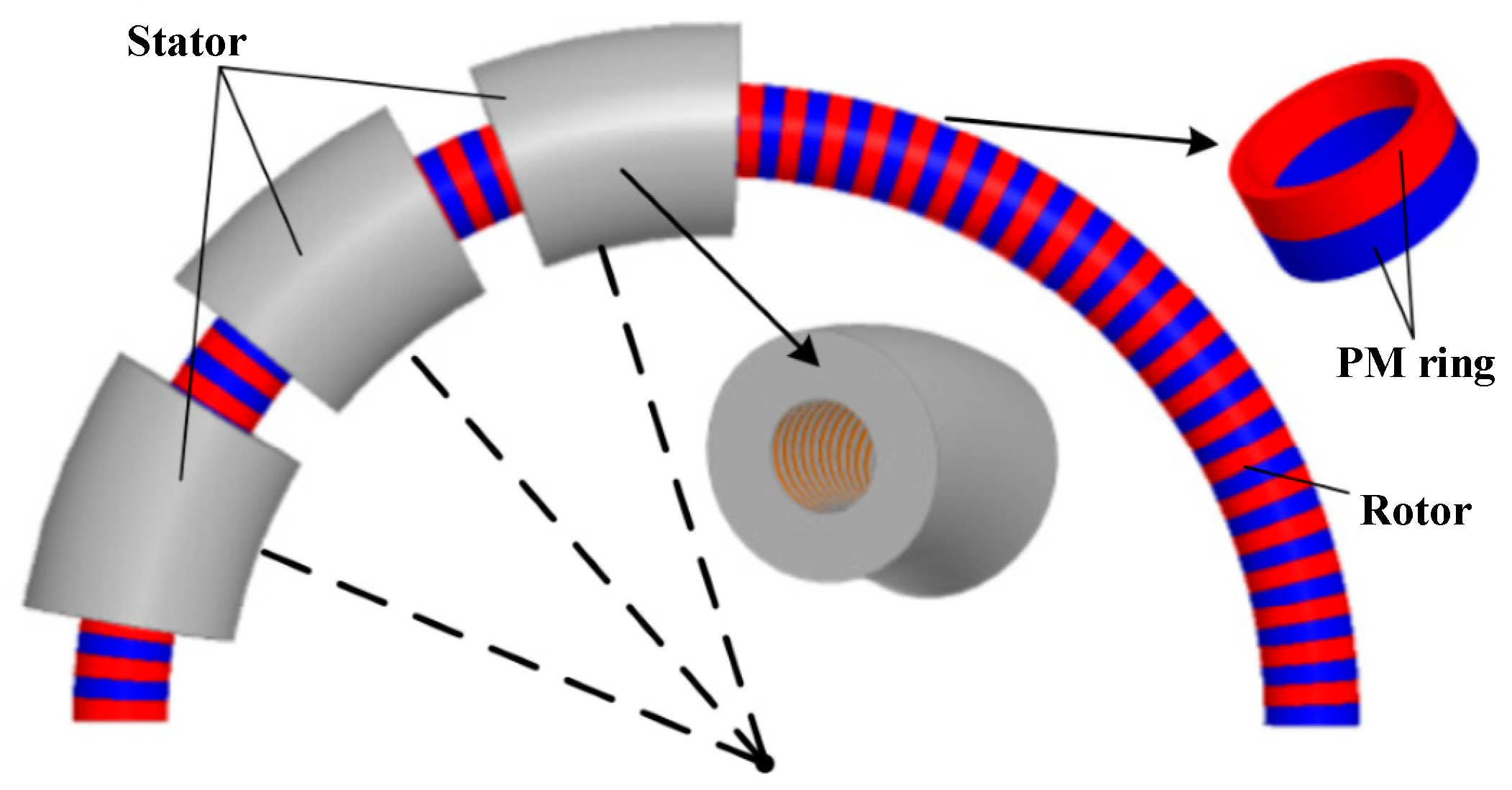
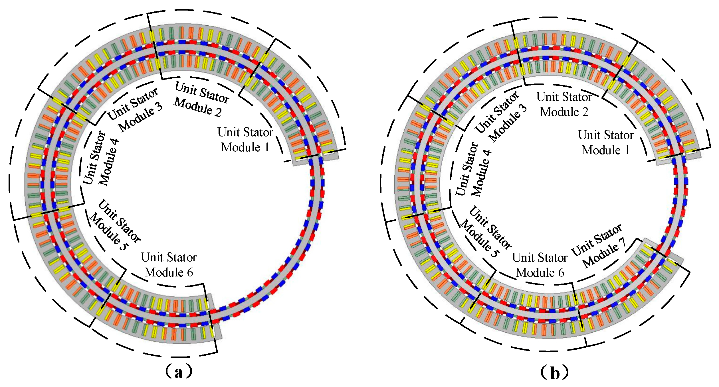
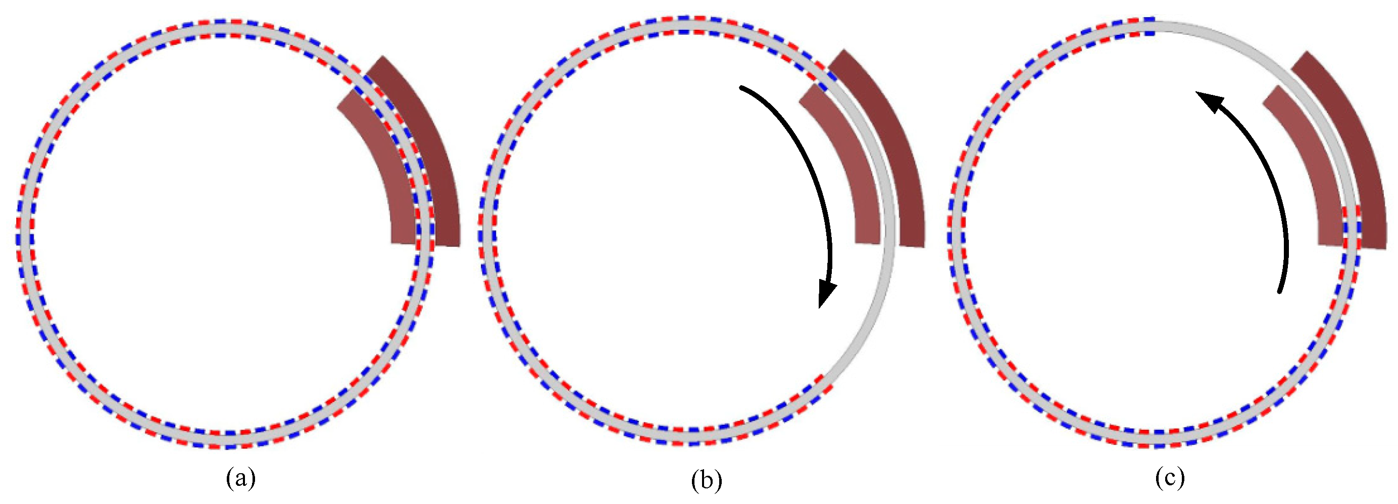
2. Configuration of Motor Model

The proposed CAPMSM was comprised of three stators and one rotor. The angle between two adjacent stator modules was θss. The stator winding used a 12-slot/10-pole fractional-slot topology. The stator center angle was θs, which was the arc angle of the stator core. The optimized stator center angle was θsopt. The rotor module consisted of a ring yoke and an unequal thickness of Halbach PM. The finite element method (FEM) was used to analyze the electromagnetic performance of four models: the conventional APMSM (Model I), the proposed CAPMSM (before optimized, Model II), the proposed CAPMSM (after optimized, Model III), and the proposed cylindrical arc Halbach PM synchronous motor (CAHPMSM) (after optimized, Model IV) as shown in Figure 1. Figure 2 shows the partial 3D configuration of the proposed model, followed by the sectional view of the 3D model shown in Figure 3.
Table 1 gives the key design parameters of the initial design, and the 2D finite element analysis of the single module is shown in Figure 4.

3. Investigation into Separating Tslot and Tend

For CAPMSM, the cogging torque, Tcog, included the slotted torque, Tslot, generated by the slotted effect and the end torque, Tend, generated by the end effect that can be written as:
T cog = T end + T slot
It is difficult to directly separate the torque, Tslot, and the torque, Tend, from the torque, Tcog. In Figure 4, a 12-slot/10-pole fractional slot structure can be seen as a one-unit motor. The torque, Tslot, of a one-unit motor can be obtained by the difference of cogging torque, Tcog, between Figure 5a,b. Therefore, the end torque, Tend, can be calculated by the difference of the total cogging torque, Tcog, and the slotting torque of K unit motors. The cogging torque can be obtained as shown in Figure 5.
T cogK = T end + K T slot
where K is the number of unit motors. Then, the torque Tslot and torque Tend can be separated by Equation (3).
{ T slot = T cogK + 1 T cogK T end = T cogK K T slot
When considering the influence of the end effect on the torque Tslot, the more accurate the K is, the more accurate the result will be. Since rotor module circumference is finite, the value of K is taken as 6 for the CAPMSM, as shown in Figure 5. The peak-to-valley value of Tslot and Tend are 2.5 Nm and 24.78 Nm respectively, as shown in Figure 6. The separation result shows that Tend is the main component of the cogging torque.

4. Optimization Method Analysis of Torque Characteristics

The cogging torque included two aspects: one was the end effect for the arc length of the stator core and the other was the slot effect caused by the interaction between the PM on the rotor and the iron core of the stator when the winding was not energized. Therefore, the cogging torque could be reduced by the following two methods.

4.1. Optimization of End Torque

4.1.1. Optimization of the Stator Center Angle

Tend consists of the left end torque, TLend, and the right end torque, TRend. TLend and TRend can be expressed in Fourier series as follows:
T Lend = a 0 + n = 1 a cn cos ( 2 n π τ p t ) + n = 1 a sn sin ( 2 n π τ p t )
T Rend = a 0 + n = 1 a cn cos ( 2 n π τ p ( t + ψ ) )   + n = 1 a sn sin ( 2 n π τ p ( t + ψ ) )
where φ is the phase angle difference between TLend and TRend, τp is pole pitch, and acn and asn are the magnitude of the nth harmonic component, respectively.
T end = T Lend + T Rend = n = 1 a n sin ( 2 n π τ p ( t + τ p 2 ) )
where an can be expressed as:
a n = 2 ( a sn cos ( n π τ p ψ ) + a cn sin ( n π τ p ψ ) )
The amplitude of end effect force is closely related to the stator central angle. The end effect force can be reduced by optimizing the stator central angle. If an = 0, φ can be written as:
ψ = τ p n π arctan ( a sn a cn )
Actually, ψ is mainly dependent on the stator center angle. Thus, there will be a theoretical θs which enables the total torque of TLend and TRend to be zero. However, TLend and TRend cannot be ideal sinusoidal waveforms and have many harmonic components. So, the harmonic coefficients of each order cannot be equal to 0 at the same time and the end effect force cannot be eliminated completely. There is an appropriate θs which enables the sum torque of TLend and TRend to be at a minimum but not zero. The end force can be optimized at a minimum only when the fundamental harmonics φopt is eliminated.
ψ opt = τ p π arctan ( a sn a cn )

4.1.2. Optimization of the Stator Adjacent Angle

Through the above optimization analysis of the stator center angle, each stator module is equivalent to a unit motor. When the conventional splicing method is adopted, the output torque and reluctance torque of the motor are proportional to the number of stator modules of the motor.
The end torque is a function of the pole pitch period. If the end torque generated by the plurality of stators are different from each other by a certain phase, the synthetic torque of the rotor subjected to the end torque of the plurality of stators may be minimized.
In this paper, taking three stators as an example, the expression of the end torque can be written as:
T Rend = a 0 + n = 1 a n sin ( 2 n π τ p t )
T Lend = a 0 + n = 1 a n sin ( 2 n π τ p t + ψ )
T end = T Lend + T Rend = n = 1 a n cos ( ψ 2 ) sin ( 2 n π τ p t + ψ 2 )
T s _ end = T Lend 1 + T Lend 2 + T Lend 3 + T Rend 1 + T Rend 2 + T Rend 3 = n = 1 a n sin ( 2 n π τ p t ) + n = 1 a n sin 2 n π τ p ( t + θ ss ) + n = 1 a n sin 2 n π τ p ( t + 2 θ ss ) + n = 1 a n sin ( 2 n π τ p t + ψ ) + n = 1 a n sin [ 2 n π τ p ( t + θ ss ) + ψ ] + n = 1 a n sin [ 2 n π τ p ( t + 2 θ ss ) + ψ ] = n = 1 a n [ sin 2 n π τ p ( t + θ ss ) ( 2 cos 2 n π τ p θ ss + 1 ) ] + n = 1 a n { sin [ 2 n π τ p ( t + θ ss ) + ψ ] ( 2 cos 2 n π τ p θ ss + 1 ) ] }
If the sum of the three stators end torque is minimized, then it should satisfy:
2 cos 2 n π τ p θ ss + 1 = 0
Therefore, the angle between two adjacent stators satisfies:
θ ss = k τ p ± τ p 3 n
where k is an arbitrary integer and n is the harmonic order.
In order to minimize the end torque, the component with the largest proportion of end torque harmonics must be determined. It can be seen from the above analysis that the sum of the end torque is still dominated by the first harmonic.
So, the angle between two adjacent stators is:
θ ss = k τ p ± τ p 3

4.2. Optimization of Slotted Torque

The slotted torque is caused by the interaction between the PM and the armature-alveolar. The slotted torque can be expressed as:
T slot = W / α
where W is the magnetic field energy, and α is the relative position angle.
The relative position of the permanent magnet and stator is shown in Figure 7. The position of the center line of the PM is represented by θ = 0. The arc length of the stator core is equal to 2π, and its practical arc length is Ls, thereby α is the angle between the center line of stator teeth and the center line of PM.
Supposing that the armature core permeability is gigantic, the magnetic field energy, W, stored in the motor can be written as:
W W a i r g a p + P M = 1 2 u 0 V B 2 d V
where B is the magnetic flux density of airgap, V is the bulk of the airgap and, PM μ0 is the magnetic permeability.
If the influences of saturation, magnetic flux leakage, and cogging effect are ignored, and the magnetic permeability of the PM is assumed to be the same as air, then B is:
B = B r h m h m + δ e
where Br is PM remanence, δe is the effective length of airgap and, hm is PM thickness.
In relation to the slotted PM motor, δe can be written as Carter coefficient (Kδ):
{ K δ = τ 1 τ 1 γ δ δ e = δ + ( K δ 1 ) δ
where δ = δ + h m / μ r , τ1 is slotting pitch, δ is the length of air-gap and, μr is relative permeability. The slotting coefficient γ can be written as:
γ = 4 π ( b 0 2 δ tan 1 ( b 0 2 δ ) ln 1 + ( b 0 2 δ ) 2 )
where b0 is stator notch width.
According to the expressions mentioned, W can be further expanded to:
W = 0 2 π R L 2 π L 2 π + δ e 0 2 π B r 2 ( h m h m + δ e ) 2 r d r d θ d L
where R is the outer diameter.
According to Equation (17), the slotting torque can be expressed as:
T slot = π 2 Z L S 2 μ 0 ( L S π δ e + δ e 2 ) × n = 1 n G n B r ( n Z / 2 p ) sin ( 2 π n Z L S α )
where Br(nZ/2p) is (nZ/2p) the harmonic component of PM remanence, Gn is the nth harmonic magnitude, Z is the slot number and, n is an integer. At the same time, nZ/2p is also an integer. It can be seen from Equation (23) that the slotted torque has great influence on the modulus of Br(nZ/2p). Thus, by choosing the appropriate value of nZ/2p, Tslot can be decreased.

5. Optimization Result Analysis of Torque Characteristics

5.1. Optimization of Stator Central Angle

A slotless CAPMSM model was built to avoid the influence of slot cogging force as shown in Figure 8a. In order to calculate the left end torque and the right end torque accurately, when rotating clockwise only the magnet that was closest to the left was reserved as shown in Figure 8b, when rotating anti-clockwise, only the magnet that was closest to the right was reserved which is shown in Figure 8c. In CAPMSM, the stator was maintained in a fixed place and the rotor spun clockwise and anti-clockwise at the same rotating speed of 67.5°/s, respectively. The simulation results are shown in Figure 9.
It can be seen from Figure 9 that TLend was positive while TRend was negative. Furthermore, they both used pole pitch θp as the minimum period.
θ p = ν × T = 67.5 / s × 0.066   s = 4.5
where v is the rotating speed and T is a period. When TLend achieves the maximum amplitude, TRend cannot achieve the minimum amplitude, and there is a time delay of Δt = 32 ms. If the time delay is Δt = 0 ms, the synthetic end torque will reach its smallest measure.
Δ θ = ν × Δ t = 67.5 / s × 0.032   s = 2.16
The left and right end torque were expanded into Fourier series as seen in Equations (4)–(9), which fluctuate with the pole pitch as the period. The phase difference is φ, and an changes with φ. When the left end torque reaches the maximum amplitude and the right end torque reaches the minimum amplitude, the synthetic end torque will reach its smallest measure. The appropriate angle is then obtained by calculating the phase of the two end torque. In the simulation of CAPMSM, if TLend is at the same place, while TRend is close to TLend, then the curve of TRend displayed in Figure 9 will move towards the left. The moved angle is Δθ.
After the stator central angle is optimized, the central angle of the stator can be calculated by:
θ sopt = θ s Δ θ = 52.075 ° 2.16 ° = 49.915 °
It can be seen from Figure 10 that after the stator central angle was optimized, the synthetic end torque was smaller than 3 Nm. The synthetic end torque was reduced when the stator central angle was optimized.

5.2. Optimization of the Adjacent Angle Between Two Stators

The end torque, Tend, is the cycle of the pole pitch, θp. When the phase angle difference between the adjacent stator end torque is 180°, the ideal total end torque generated by the adjacent stator end effect is zero. However, since Tend is not a desirable sinusoidal waveform that includes a large amount of high harmonic components, Tend cannot be reduced to zero.
For the purpose of offsetting the end torque, Tend, between the adjacent stator, the phase angle difference between the adjacent stator can be expressed as:
θ ss = k τ p ± τ p 3 n
Consequently, the phase angle difference between stator modules A and B is maintained using θss, meanwhile the adjacent angle between stator modules B and C is maintained using the same value:
θ ss = 27 τ p τ p 3 = 120 °
It can be seen from Figure 11 that, after the stator adjacent angle is optimized, the peak-to-valley value of end torque decreased from 35.35 Nm to 4.36 Nm.

5.3. Unequal Thickness Halbach PM

Since the unequal thickness of Halbach PM is used, the flux density distribution of the air gap is closer to sinusoidal, which can weaken the cogging torque. The magnetic field on one side is enhanced, while it is weakened on the other side. Therefore, both the radial thickness and the amount of PM can be reduced. In Model III, the radial thickness of the PM was 2 mm and, in Model IV, the radial thickness of the PM was labeled as shown in Figure 12. For the same output torque, Model IV had a lower PM usage than that of Model III. Figure 13 shows that the peak-to-valley value of output torque decreased from 3.96 Nm to 1.47 Nm.

5.4. Change the Central Angle of Slot Pitch

From the above analysis, it can be seen that by reasonably selecting the number of armature slots and the number of poles, changing the Brn plays a major role in the slotted torque and can weaken the slotted torque. The cycle of the slotted torque γ is the least common multiple (LCM) of slots, Z, and pole pairs, p. The amplitude will decrease with the increasing of γ:
γ = L C M [ Ζ , 2 p ]
When the pole pairs, p, of the rotor are constant, the number of slots of the stator can be changed by changing the central angle of slot pitch, θsp, the LCM of stator slots, and the rotor poles can be increased, thereby the fundamental frequency of the slotted torque is increased. The amplitude can be reduced by increasing the fundamental frequency of the slotted torque.
In the initial design of the CAPMSM, the single rotor was selected to be 12 slots and 8 poles, with the central angle of slot pitch at 3°. The motor had 120 slots and 80 poles. Then γ1 was:
γ 1 = L C M [ Ζ , 2 p ] = 240
It was necessary to increase the LCM of stator slots and poles to reduce the slotted torque. The central angle of slot pitch was changed to 3.75°. The motor had 96 slots and 80 poles. Then γ2 was:
γ 2 = L C M [ Ζ , 2 p ] = 480
It can be seen from Figure 14 that after the central angle of slot pitch was optimized, the magnitude decreased from 8.42 Nm to 2.21 Nm. It can be seen from Figure 15 that the peak-to-valley value of output torque decreased from 35.35 Nm to 1.47 Nm after adopting the optimized stator central angle, the angle between two adjacent stators, the unequal thickness of Halbach PM, and the central angle of slot pitch.
Figure 16 shows the air gap flux density distributions of the four models. Because of the 4mm radial thickness of the permanent magnet of Model I, the peak value of air gap flux density of Model I was greater than those of other models. Figure 16 shows that the sinusoidal property of air gap flux density in Model II was the worst, but that of Model IV was the best. Further, harmonic spectra analysis of air-gap flux density of the four models was carried out, which is shown in Figure 17. The 5th and 7th harmonic components occupied the main proportion, and the 3rd, 5th and, 7th harmonic components of Model II were larger than those of Model IV.
From Figure 18, the flux density of the air gap side can be increased, and the flux density of the rotor yoke can be reduced by using Halbach PMs with different thicknesses. Therefore, the radial thickness and PM consumption can be reduced.

6. Conclusions

This paper proposes techniques to reduce torque ripple of CAPMSM including optimizing stator central angle, changing angle between two adjacent stators, adopting unequal thickness of Halbach PMs, and adjusting the central angle of slot pitch. Fourier analysis and FEM simulation were used to obtain an optimal stator central, θsopt, a suitable angle between two adjacent stators, θss, and an appropriate central angle of slot pitch, θsp. The method was proposed to separate the cogging torque, Tcog, into the torque, Tslot, caused by slotting and the end torque, Tend, caused by the end effect of stator. In Table 2, the torque ripple of the proposed CAPMSM (Model III) and CAHPMSM, CAPMSM with Halbach (Model IV), was 0.87% and 2.83% smaller than that of Model I, respectively. When the optimization model was established, the torque ripples decreased from 31.73% to 1.17%. The optimized CAPMSM can meet the requirements of tracking accuracy for a large telescope, whose torque ripple is below 2%.

Author Contributions

Conceptualization, S.F. and S.X.; methodology, S.F. and S.X.; software, Z.P.; validation, S.X. and Z.P.; formal analysis, H.Y.; investigation, S.F. and S.X.; resources, Z.P.; data curation, S.X.; writing—original draft preparation, S.X. and Z.P.; writing—review and editing, S.F. and H.L.; visualization, H.Y.; supervision, S.F.; project administration, H.L.; funding acquisition, S.F.

Acknowledgments

This work was supported in part by the Joint Research Fund in Astronomy (U1731133) under a cooperative agreement between the National Natural Science Foundation of China (NSFC) and the Chinese Academy of Science (CAS).

Conflicts of Interest

The authors declare no conflict of interest.

References

  1. Gilardi, G.; Szeto, K.; Huard, S.; Park, E.J. Finite element analysis of the cogging force in the linear synchronous motor array for the thirty meter telescope. Mechatronics 2011, 21, 116–124. [Google Scholar] [CrossRef]
  2. Chu, W.Q.; Zhu, Z.Q. Investigation of torque ripples in permanent magnet synchronous machines with skewing. IEEE Trans. Magn. 2013, 49, 1211–1220. [Google Scholar] [CrossRef]
  3. Hong, H.; Yoo, J. Shape design of the surface mounted permanent magnet in a synchronous machine. IEEE Trans. Magn. 2011, 47, 2109–2117. [Google Scholar] [CrossRef]
  4. Zheng, P.; Zhao, J.; Han, J.; Wang, J.; Yao, Z.; Liu, R. Optimization of the magnetic pole shape of a permanent-magnet synchronous motor. IEEE Trans. Magn. 2007, 43, 2531–2533. [Google Scholar] [CrossRef]
  5. Hwang, C.C.; Wu, M.H.; Cheng, S.P. Influence of pole and slot combinations on cogging torque in fractional slot PM motors. J. Magn. Magn. Mater. 2006, 304, e430–e432. [Google Scholar] [CrossRef]
  6. Lee, S.K.; Kang, G.H.; Hur, J.; Kim, B.W. Quasi-zero torque pulsation of surface permanent magnet synchronous motor for ship gyro stabilizer by pole/slot number and air-gap designs. IEEE Trans. Magn. 2014, 50, 7019704. [Google Scholar] [CrossRef]
  7. Zhou, Y.; Li, H.S.; Meng, G.W.; Zhou, S.; Cao, Q. Analytical calculation of magnetic field and cogging torque in surface-mounted permanent magnet accounting for any eccentric rotor shape. IEEE Trans. Ind. Electron. 2015, 62, 3438–3447. [Google Scholar] [CrossRef]
  8. Wu, L.J.; Zhu, Z.Q.; Staton, D.A.; Popescu, M.; Hawkins, D. Comparison of analytical models of cogging torque in surface-mounted PM machines. IEEE Trans. Ind. Electron. 2012, 59, 2414–2425. [Google Scholar] [CrossRef]
  9. Dosiek, L.; Pillay, P. Cogging torque reduction in permanent magnet machines. IEEE Trans. Ind. Appl. 2007, 43, 1565–1570. [Google Scholar] [CrossRef]
  10. Zhang, H.; Kou, B.; Jin, Y.; Zhang, H. Investigation of auxiliary poles optimal design on reduction of end effect detent force for PMLSM with typical slot-pole combinations. IEEE Trans. Magn. 2015, 51, 8203904. [Google Scholar]
  11. Chang, J.J.; Ma, W.; Fan, Y.; Yang, H.; Huang, J. Design and optimization of arc permanent magnet synchronous motor used on large telescope. IEEE Trans. Magn. 2012, 48, 1943–1947. [Google Scholar]
  12. Li, B.; Zhao, J.; Liu, X.D.; Guo, Y.G.; Li, J. Detent force reduction of an arc-linear-permanent-magnet synchronous motor by using compensation windings. IEEE Trans. Magn. 2017, 64, 3001–3011. [Google Scholar] [CrossRef]
  13. Ho, S.L.; Wang, Q.; Niu, S.; Fu, W.N. A novel magnetic-geared tubular linear machine with Halbach permanent-magnet arrays for tidal energy conversion. IEEE Trans. Magn. 2015, 51, 811360. [Google Scholar] [CrossRef]
  14. Wang, H.; Fang, S.; Jahns, T.M.; Yang, H.; Lin, H. Various new magnet arrangements used in dual-stator permanent-magnet vernier machine for large telescope drive. In Proceedings of the 2018 IEEE International Magnetics Conference (INTERMAG), Singapore, 25 October 2018. [Google Scholar]
  15. Jin, P.; Fang, S.; Ho, S. Distribution characteristic and combined optimization of maximum cogging torque of surface-mounted permanent-magnet machines. IEEE Trans. Magn. 2018, 54, 8200505. [Google Scholar]
  16. Du, Z.; Lipo, T.A. Efficient utilization of rare earth permanent-magnet materials and torque ripple reduction in interior permanent-magnet machines. IEEE Trans. Ind. Appl. 2017, 53, 3485–3495. [Google Scholar] [CrossRef]
  17. Liu, G.; Du, X.; Zhao, W.; Chen, Q. Reduction of torque ripple in inset permanent magnet synchronous motor by magnets shifting. IEEE Trans. Magn. 2017, 53, 8100713. [Google Scholar] [CrossRef]
  18. Liu, C.; Yu, H.; Hu, M.; Liu, Q.; Zhou, S. Detent Force Reduction in Permanent Magnet Tubular Linear Generator for Direct-Driver Wave Energy Conversion. IEEE Trans. Magn. 2013, 49, 1913–1916. [Google Scholar] [CrossRef]
  19. Hu, Y.; Zhu, S.; Liu, C.; Wang, K. Electromagnetic Performance Analysis of Interior PM Machines for Electric Vehicle Applications. IEEE Trans. Energy Convers. 2018, 33, 199–208. [Google Scholar] [CrossRef]
  20. Zou, J.; Lan, H.; Xu, Y.; Zhao, B. Analysis of Global and Local Force Harmonics and Their Effects on Vibration in Permanent Magnet Synchronous Machines. IEEE Trans. Energy Convers. 2017, 32, 1523–1532. [Google Scholar] [CrossRef]
Figure 1. Machine configurations. (a) Model I; (b) Model II; (c) Model III; (d) Model IV.
Energies 12 00362 g001
Figure 2. A 3D drawing of the partial arc permanent magnet (PM) motor.
Energies 12 00362 g002
Figure 3. A 3D sectional drawing of the partial arc PM motor.
Energies 12 00362 g003
Figure 4. A 2D finite element analysis of the single module.
Energies 12 00362 g004
Figure 5. Analysis models for separating Tslot and Tend. (a) Six unit motors; (b) 6 + 1 = 7 unit motors.
Energies 12 00362 g005
Figure 6. Waveforms of cogging torque after separation.
Energies 12 00362 g006
Figure 7. The relative position for the permanent magnet and armature.
Energies 12 00362 g007
Figure 8. End torque analysis model for slotless CAPMSM. (a) Overall model; (b) left end torque analysis model; (c) right end torque analysis model.
Energies 12 00362 g008
Figure 9. Calculated end torque TLend and TRend by finite element method (FEM).
Energies 12 00362 g009
Figure 10. Calculated end torque after stator central angle is optimized.
Energies 12 00362 g010
Figure 11. Comparison of end torque when θss is 120° and 135°, respectively.
Energies 12 00362 g011
Figure 12. Single piece partial magnetization schematic and thickness labeling.
Energies 12 00362 g012
Figure 13. Comparison of torque ripple between Models III and IV.
Energies 12 00362 g013
Figure 14. Comparison of cogging torque when θsp is 3.75° and 3°, respectively.
Energies 12 00362 g014
Figure 15. Comparison of output torque among Models II, III and IV.
Energies 12 00362 g015
Figure 16. The air-gap flux density distributions of the four models.
Energies 12 00362 g016
Figure 17. The harmonic spectra of air-gap flux density of the four models.
Energies 12 00362 g017
Figure 18. Flux lines distribution in Model IV.
Energies 12 00362 g018
Table 1. Items of the initial cylindrical arc permanent magnet synchronous motor (CAPMSM) model.
ItemsSymbolValue
Stator Outer diameterDout (mm)480
Air gapg (mm)1.2
Stator central angleθs (°)56.25
Angle between two adjacent statorsθss (°)135
Central angle of pole pitchθp (°)4.5
Central angle of slot pitchθsp (°)3
Stack lengthh (mm)70
Slot numberSnum40
Rotor pole-pair numberPnum64
CurrentI (A)15
VoltageU (V)15.82
Turns per slotN20
Current densityJ (A/mm2)7.5
Efficiencyη (%)67.8%
Rated speednn (rpm)11.25
PM gradeNdFeB40H
Steel gradeDW310-35
Table 2. Comparisons of the four models.
ItemsSymbolModel IModel IIModel IIIModel IV
Stator Outer diameterDout (mm)480
Air gapg (mm)1.2
Stator central angleθs (°)56.2552.07549.91549.915
Angle between two adjacent statorsθss (°)90135120120
Stack lengthh (mm)50707070
Central angle of pole pitchθp (°)5.6254.5
Central angle of slot pitchθsp (°)533.753.75
Rated output torqueTm (Nm)120126.65126.56126.04
Torque rippleκ4%31.73%3.13%1.17%

