Article

A Distributed Generation Hybrid System for Electric Energy Boosting Fueled with Olive Industry Wastes

Department of Electrical Engineering, Escuela Politécnica Superior, University of Jaén, 23700 Linares, Spain
*
Author to whom correspondence should be addressed.
Energies 2019, 12(3), 500; https://doi.org/10.3390/en12030500
Submission received: 31 December 2018 / Revised: 29 January 2019 / Accepted: 31 January 2019 / Published: 5 February 2019
(This article belongs to the Section A4: Bio-Energy)

Abstract

:
This paper presents the theoretical model and the simulation of a cutting edge hybrid power system composed of an externally-fired gas turbine (EFGT) coupled with an organic Rankine cycle (ORC) as a bottoming unit for the maximization of electrical power. The power plant is fed with different biomass sources from olive industry wastes (pruning, dry pomace, stones, leaves and twigs), providing more than 550 kW of electric power and a net electrical efficiency of 26.0%. These wastes were burnt directly at atmospheric pressure in an EFGT, producing 400 kW of electric power and exhaust gases at 300 °C. Ten suitable ORC working fluids have been studied to maximize the electric power generation: cyclohexane, isohexane, pentane, isopentane, neopentane, R113, R245fa, R365mfc, R1233zd and methanol. The best fluid was R1233zd, reaching 152.4 kW and 22.1% of ORC thermal efficiency; as drawback, however, R1233zd was not suitable for Combined Heat and Power CHP applications due its lower condensation temperature. Thus, despite R113 gave minor electricity production (137.5 kW) this allowed to generate additional thermal power (506.8 kW) in the way of hot water at 45 °C.

1. Introduction

The olive tree (Olea europaea L.) is one of the best well known crops of the Mediterranean region. Its cultivation and the production of olive oil have been anchored deeply in the history of the Mediterranean countries for more than 7000 years. The area where modern cultivation is most intensive is Spain, followed by Italy and Greece [1]. The olive oil sector is nowadays facing several obstacles that push towards the need of a new approach, not only to cultivation, production, logistics and consumption but also to by-product and waste management and, in the final analysis, to enhance sustainability. Thereby, it is crucial to adopt a holistic vision to manage the olive oil sector as a whole, and here is where the value chain management plays a crucial role.
The olive oil value chain generates variety of by-products and wastes, particularly during the agricultural phase (harvesting tasks) and oil production, such as olive pruning residues, olive pits, pomace, olive mill waste water and leaves and branches [2]. The amount and physico-chemical properties of the wastes produced depend on the olive oil extraction method. Taking into account the more extended and high efficiency oil extraction processes in Spain (continuous 2-phases) the wastes generated at the mill are presented in Figure 1 (highlights in dashed lines). One of the most abundant sources of wastes in the olive oil value chain is the pruning of the olive trees. It is estimated that one hectare of olive grove produces 2–3 tons of prunings per year [3].
Olive leaves and small branches or twigs are also considered an olive oil industry waste. According to Malheiro et al. [4], this residue can amount to 8–10% of the total weight of olives processed at the mill. Nowadays, their separation, storage and elimination entail an increasing cost for the mill owners [5]. Table 1 summarizes the rate of production, cost and main properties of the wastes generated during the main phases of the olive oil value chain [2,3,4,6].
Biomass is increasingly becoming an attractive option to replace conventional fossil fuels for heat and power generation. The application of externally firing technologies is becoming more popular, as they allow using low-quality fuels, compared to other solutions, such as internal combustion machines. Specifically, the usage of a combination of externally firing gas turbines (EFGT) and organic Rankine cycle (ORC) generators for distributed generation has been considered by many authors [7,8,9,10,11,12]. EFGT and ORC generators are mainly cogeneration systems where the thermal power generated is approximately three times higher than the electrical power, reaching in many cases low electrical efficiencies (10–20%) when they are coupled with biomass systems (combustion or gasification) [5,13,14,15]. Moreover, a need to maximize the electrical energy efficiency is emerging because of the continuous growing of the smart-grids and their integration with renewables and other distributed generation technologies in future smart cities.
In spite of the commercial development of both technologies and the numerous research works reported in the literature, only a few authors have focused on the combination of gas turbines and ORC to increase the electrical power generation. As a matter of fact, the gas turbine waste heat is largely sufficient to activate a bottoming ORC generator. In this sense, Ivernizzi et al. [16] reported a hybrid system composed of a micro-gas turbine (fueled with natural gas) and a bottoming ORC for the electrical energy enhancement. This system could reach electrical efficiencies of 40% for a nominal electric power of 100 kW. In the same way, Camporeale et al. [17] presented a techno-economic study of a biomass combustion system where the combination of EFGT-ORC resulted more profitable than the simple EFGT option, because of its higher electrical efficiency. Lora and Silva [18] compared a biomass combustion system coupled with a 50 kW ORC generator with a system based on double shaft intercooled EFGT. This system showed an improvement in electrical efficiency up to 21%; however, this work did not study the combination of both systems. Finally, Vera et al. [19] performed the evaluation of an EFGT-ORC system fueled with a downdraft gasifier for olive tree pruning, reaching a maximum net electric efficiency of 20.5%. Despite this work studied a similar approach (EFGT-ORC), it is important to highlight that the present study proposes a different biomass conversion technology (an atmospheric combustor), the study of ten suitable ORC working fluids and it has been calculated the optimum operating conditions for each olive oil industry waste: stones, dry pomace, pruning, leaves and twigs. Due to the important contribution of reference [19] related with the present work, and to identify the specific improvements of this work respect to [19], a comparison between the optimum results of both works have been included and discussed in the final section.
Therefore, there is a lack of technical bibliography about the use and performance of gas turbines (and more specifically, EFGT) coupled with ORC systems. There is little information about the study of the different working fluids acceptable for this temperature range (200–350 °C). In the present work it has performed a study in depth of the different fluids currently used commercially and beyond that, we have proposed the use of other types of working fluids that allow increasing the electric efficiency of the plant. The main objective of this work is the modeling and energetic simulation of a power plant composed of an external combustion chamber, gas turbine and an ORC generator, which can maximize the electric energy produced. The optimization of the working parameters has been carried out using the Cycle-Tempo® software (Release 5, Delft University of Technology, The Hague, The Netherlands).

2. Materials and Methods

2.1. Olive Industry Wastes

Olive oil industry wastes represent an abundant biomass source in the Mediterranean countries. The picture and morphology of the most relevant residues of the olive oil industry are depicted in the following figures (See Figure 2).
Table 2 summarizes the proximate and ultimate analyses of these olive industry wastes.
Due to their excellent energetic properties (LHV), low moisture content and ashes, the residues most appropriate for energetic production are olive stones and prunings (previously chipped). A drying stage would be necessary to use pomace to reduce the moisture content below 20%. Twigs and leaves present low energy density (12.3 MJ/kg) and a high ash content (8.71%), which renders their valorization using combustion chambers technically non-viable. A possibility for the valorization of this by-product has been published in a work prepared by [5], which describes the valorization of residues with ash content up to 20% (weight) with an updraft gasifier.

2.2. Plant Description

This novel distributed generation plant is able to produce around 400 kW of electric power and, depending on the ORC working fluid selected, a surplus electric and suitable thermal power for heating necessities. The EFGT generates approximately 2/3 of the electrical power; and the rest is generated by the ORC subsystem, which is capable of operating with the EFGT exhaust gases when it reaches the steady state conditions.
For the modelling and simulation of the combined power plant, the following general considerations have been assumed: (a) the biomass feedstock is composed exclusively of wastes from the olive industry; (b) the environmental reference state is fixed at 25 °C and atmospheric pressure (1.013 bar); and (c) finally, the power plant is operating in steady state conditions. The main features of the two sub-systems are described in the following sections.

2.2.1. Externally Fired Gas Turbine (EFGT)

An EFGT is composed of the following devices: an external combustion chamber, where the solid biomass is burned at atmospheric pressure; a high temperature heat exchanger (HTHE), where the thermal energy of the flue gases is transferred to the working fluid (in this case, clean air); and a compressor-turbine group connected to an electric generator. It is important to notice that the components of an EFGT are similar to a conventional gas turbine, and that the only difference being the external combustion chamber element; in this case, the fuel is not compressed up to the operating pressure of the compressor, therefore avoiding higher electrical consumptions [20]. The use of an EFGT introduces two key factors: the size and cost of the HTHE will depend on the optimum operating parameters and will be related with the economic feasibility of the power plant.
Part of the hot air at the turbine exit is recirculated back to the combustion chamber through a control valve with the objective to increase the overall thermal efficiency of the system. Finally, the flue gases from the HTHE and the hot air from the turbine are mixed and used as heat source in the ORC subsystem to increase the net electrical power. The waste heat temperature can reach 300 °C.
EFGT systems have been applied to diverse fields including different fuel sources such as pulverized coal, natural gas, biomass combustion heat among others [12]. EFGT manufacturers such as GHH (Gelsenkirchen, Germany), Garret (Phoenix, ArizonaUSA), the US Army, Talbott (Stone, UK), Enel (Rome, Italy) and British Gas (Windsor, UK) have been presented on the market since the last years with sizes ranging from 0.05 to 50 MW. It is necessary to mention at this point that the HTHE technology is a critical element to the EFGT success: a high quality manufacturing process and the use of materials capable of operating under high temperature ranges will improve the overall electric efficiency. In this paper, the HTHE is composed of nickel based super alloys and allows the turbine inlet temperature (TIT) to reach 850–900 °C [12].
The EFGT modelling has been carried out using Cycle-Tempo®, and the layout of the simulation is shown in Figure 4. This figure shows the whole scheme of the EFGT-ORC power system, it consists of three main sub-systems: (1) the external combustion chamber fueled with olive industry wastes (green line); (2) the EFGT, where the main electrical power is produced, composed of a compressor, turbine-generator in the same shaft, a HTHE and a mixer; and (3) the ORC generator, mainly composed of a pump, a regenerator, an evaporator, an expander-generator and a condenser.
The optimum operating parameters such as compressor pressure ratio, air factor, air mass flow, electric efficiency among others have been analyzed in order to maximize the electric power generation according to the performance conditions summarized in Table 3 [21,22].
Furthermore, the two key parameters for the techno-economical optimization of the externally fired combustion turbine will be the variation in the hot side temperature, as well as the mass flow of combustion gases to reach a temperature of 1000 °C. The higher the mass flow, the higher the cost of the HTHE and piping costs of the plant will be.
The hot side temperature difference describes the variation between the flue gases temperature (set at 1000 °C) and TIT (set in this work at 875 °C). On the other hand, the general expression of a turbine or compressor mechanical power developed by the EFGT sub-system can be depicted as follows:
P c = m ˙ a i r ( h o u t h i n ) η i s η m
P t = m ˙ a i r ( h o u t h i n ) η i s η m
where Pt and Pc symbolize the turbine and compressor mechanical power (kW), respectively; m ˙ a i r the air mass flow of the EFGT (kg/s); (houthin) the enthalpy variation between the outlet and inlet (kJ/kg); ηis and ηm the isentropic and mechanical efficiency of the turbine and compressor, respectively.
Thus, the net electrical power ( P e E F G T ) and efficiency ( η e E F G T ) of this sub-system can be expressed as follows:
P e E F G T = ( P t P c ) η g e n
η e E F G T = P e E F G T m ˙ b L H V b
where ηgen represents the generator electrical efficiency coupled in the same shaft with the compressor and turbine (Figure 3); m ˙ b is the biomass consumption (kg/s) and LHVb the lower calorific value of the biomass fueled in the EFGT sub-system (kJ/kg).

2.2.2. Organic Rankine Cycle (ORC)

The thermal power of the EFGT exhaust gases, typically available at 300 °C, can be used in an ORC generator for the recovery of this waste heat source. The operation of the ORC is comparable to a steam Rankine cycle, but it uses an organic fluid as working medium instead of water. Basically, as can be observed in Figure 3 (lower part), the ORC subsystem is composed of a pump, an evaporator, an expander and a condenser. The organic fluid is brought by the pump to the evaporator at the working pressure. During this stage the working fluid is heated and vaporized under critical conditions. The hot steam moves a turbine where it expands near to the condensation pressure (this device is normally called expander); then, it is converted to saturated liquid in the condenser. To obtain a better thermodynamic efficiency of the cycle, a regenerator is used for the recovery of the thermal energy at the expander outlet, preheating the compressed organic fluid before the evaporator.
The possibility of selecting the proper working fluid is the most important degree of freedom in ORC design. The choice of fluid affects the thermodynamic cycle, the performance and cost of components (expander and heat exchangers), the plant layout, the safety requirements, etc. According to the extensive literature review focused on the best selection criteria [23,24,25], it is concluded that there is not a single organic fluid that will fulfill all the preferred standards. However, there are some key factors for determining the final selection, the working fluid should be: commercially available at a reasonable specific cost, nonflammable, nontoxic, compatible with materials (lubricants, elastomers, metals, etc.) and environmentally benign (ozone depletion potential and global warming potential). From a thermodynamic point of view, the best working fluid should have suitable critical values, molecular complexity and mass and acceptable condensation temperature (for CHP applications) [26].
In this paper, ten dry organic fluids have been analyzed and studied as possible and suitable working fluid: cyclohexane, isohexane, pentane, isopentane, neopentane, R113, R245fa, R365mfc, R1233zd and methanol. Table 4 summarizes the main thermo-physical and environmental properties of the fluids studied [26].
It is important to stress that the maximum temperature corresponds with the maximum operating value that the organic fluid can withstand without showing signs of instability or thermo-chemical degradation. When an organic fluid shows thermo-chemical degradation, its molecules change, and can even transform into different compounds and thus reduce the efficiency and useful life of the plant. In the present work we will use an turbine inlet temperature 10 °C below the maximum operating value, whenever the rest of operating conditions allow it, as for example with the pinch point limits and stack temperature.
The final selection of the best organic fluid will be based on the thermodynamic efficiency of the organic Rankine cycle (ηORC). Also, in this paper and particular application (olive oil production), it is important to take into account other energetic features as e.g., the possibility to produce thermal power for cogeneration applications (CHP). The ORC thermodynamic efficiency with an internal heat exchanger (regenerator) can be defined as the ratio of the net thermal power output to the heat supplied:
η O R C = W Q i n = P exp P p m ˙ O R C Δ h E V
where the Δ h E V is the enthalpy variation in the evaporator (kJ/kg) and m ˙ O R C the mass flow of the ORC working fluid (kg/s).
The expander and pump thermal powers (Pexp, Pp) are expressed in the following equations:
P exp = m ˙ O R C Δ h exp
P p = m ˙ O R C Δ h p
where Δhexp and Δhp represents the enthalpy variation of the expander and pump, respectively.
According to the above equations, the net electric power and efficiency of the ORC subsystem can be calculated as follows:
P e O R C = P exp η i s η m η g e n P p η i s η e m
η e O R C = P e O R C m ˙ O R C Δ h E V
where ηis represents the isentropic efficiency of the pump and expander; ηm the expander mechanical efficiency; ηgen the generator electric efficiency coupled to the expander and ηe-m the pump electro-mechanical efficiency.
The performance parameters and technical constraints of the ORC sub-system model (carried out in Cycle-Tempo®) are summarized in Table 5 [5,17,27,28].
The maximum ORC working pressure and expander inlet temperature are limited to 25 bar and 10 °C under the maximum operative temperature (see Table 4), respectively, to ensure working under safe conditions, as well as the thermo-chemical stability of the working fluid. The pinch point temperature difference (ΔTpinch) is an important technical parameter in the evaporator. It can be defined as the difference between waste heat exit temperature from the evaporation region and saturation temperature corresponding to evaporation pressure [28]. It is important to notice that lower ΔTpinch (<10 °C) results in important technical and material costs for the evaporator [26]. Finally, the minimum stack temperature has been set at 100 °C, to avoid undesirable condensates in pipes, stacks and other equipment.
In order to improve the energy exploitation of the ORC cycle, several dimension and economics parameters have been considered in this work. Apart from ηORC (depicted in the Equation (5)), four performance indexes are going to be introduced and analyzed as key indicators of the ORC sub-system: sum of the heat transfer coefficients (∑UA) of the main heat exchangers (recuperator, condenser and evaporator), ORC specific work (WORC), turbine volumetric expansion ratio (VER) and ORC fluid-to-hot source mass flow ratio (MFC). These indexes can be calculated according to the following equations [29]:
UA = 1 m ˙ f g ( Q R E C L M T D R E C + Q C O N L M T D C O N + Q E V A L M T D E V A )
W O R C = P e O R C m ˙ O R C
V E R = v o u t v i n
M F R = m ˙ O R C m ˙ f g
where QREC, QCON and QEVA are the total heat transmitted (kW) in the recuperator, condenser and evaporator, respectively; LMTD the Logarithmic Mean Temperature Difference for a heat exchanger; vout and vin the specific volume (m3/kg) of the working fluid at the expander outlet and inlet, respectively; and, finally, mORC and mfg the mass flow (kg/s) of the ORC working fluid and hot source (in this case flue gases at 300 °C from the EFGT exhaust).
According to Branchini et al. [29], WORC represents the working fluid mass flow demanded for an assigned design output power and thus it is correlated with the size of the system; VER is an indicator of the expander features, namely the type of turbine and its dimensions. MFR provides the flow rate of ORC working fluid necessary per unit of flue gases mass flow (hot source).
Finally, the parameter ∑UA represents the total of heat exchangers surfaces involved in the ORC cycle: recuperator (REC), condenser (CON) and evaporator (EVA) and it is an indicator of these heat exchangers costs [29].
To conclude this section the net electrical efficiency of the hybrid power generation system (EFGT-ORC) is calculated according to the following expression:
η e = P e E F G T + P e O R C P a u x m ˙ b L H V b
where Paux represents the auxiliary electrical consumption of other components, such as pumps and compressors, P e E F G T and P e O R C the electric power generated by the EFGT and ORC units, respectively.
Finally, depending on the condensation temperature of the ORC working fluid, the power plant proposed may generate thermal power for the heating needs of the olive mill or even for district heating applications. In that case, the CHP efficiency can be calculated as follows:
η C H P = P e E F G T + P e O R C + m ˙ w C p Δ T P a u x m ˙ b L H V b

3. Results and Discussion

The power plant modeling and simulation layout, carried out in Cycle-Tempo®, is depicted in Figure 4. This energy software has been used to calculate and validate the optimum operating conditions of the EFGT-ORC plant for the different feedstocks proposed. Figure 4 shows the best operating conditions for olive tree pruning as biomass fuel (464.4 kg/h) and R1233zd as ORC working fluid. As can be seen, the power plant is able to produce around 400 kW of electric power by EFGT system and 152.4 kW through ORC unit, operating with the mix of exhaust air from the turbine outlet and flue gases from the external combustion chamber (pipe 17 in Figure 4). This innovative approach allows generating more than one electric kWh per kg of biomass input (olive tree pruning, dry pomace and stones). Concretely, in this case, this value (also named coefficient of electric energy generation, α) reaches 1.19 kWh/kg for pruning, 1.23 kWh/kg for dry pomace, 1.28 kWh/kg for olive stones. These values are considerably higher than many existing biomass power plants for small, medium and high scale generation (α < 1.0 kWh/kg) [30,31].
The optimum operating conditions (in steady state) of the ORC-EFGT system were calculated in the following sections. In all simulation the performance parameters of Table 3 and Table 5 have been taken into account.

3.1. EFGT Results

The net electrical efficiency of the EFGT system ( η e E F G T ) with the compressor pressure (Pc) is depicted in Figure 5, the variability of the electrical efficiency has been studied at different TITs from 800 °C to 950 °C. The optimum performance parameters have been calculated taking into account the technical constraints listed in Table 3. It can be seen as the η e E F G T increases with the compressor pressure reaching a maximum: e.g., the optimum Pc for TIT = 800 °C is around 4.0 bar reaching an electrical efficiency of 15.6%; while for TIT = 950 °C the optimum Pc is around 6.0 bar, reaching an electrical efficiency of 21.2%. It can be assumed that a high TIT ensures higher electrical efficiency at all pressure ratios (e.g., the η e E F G T increases from 15.6% to 21.2% when TIT increases from 800 to 950 °C). However, operating temperatures above 900 °C needs expensive materials and complex cooling systems for the turbine blades and HTHE, increasing the investment, operating and maintenance costs [32].
The HTHE is one of the most critical components in the EFGT system. The material cost, which is high, and the plant size must be carefully assessed and optimized. It is worth to mention that these components can be found as commercial equipment, and that this innovative generation plant could be considered as an alternative to microturbine plants (fueled with natural gas).
The performance parameters to determine the HTHE efficiency are: hot side temperature difference (ΔThot) and the heat exchanger losses. Figure 6 shows the performance influence of this key equipment for all the olive industry wastes: stones, prunings and dry pomace at 10% of moisture content and leaves and twins at 8.5%. The parameter analyzed is the ΔThot, which is the difference between the temperature of the combustion gases (pipe 19, in Figure 4) and TIT (pipe 14). The results show that η e E F G T decreases when ΔThot rises from 50 °C to 200 °C for all the wastes: e.g., from approximately 21.2% to 16.0% for olive stones, prunings and dry pomace and from 20.0% to 15.0% for leaves and twins. This entails a decrease in the total heat transmitted between both fluids in the HTHE. The energy efficiency of the HTHE has been set at 90% (Table 3).
It must be noticed that, for a determined flue gases temperature at the external combustion chamber outlet (pipe 19, Figure 4), higher ΔThot entails lower TITs. When ΔThot is fixed at 200 °C and flue gases at 1000 °C, TIT must be fixed at 800 °C. Therefore, η e E F G T decreases considerably according to Figure 6.
Finally, a TIT of 900 °C and a ΔThot of 100 °C result in a surface for the heat exchanger of 150 m2 with a tube length of 8 m, approximately. The corresponding values for ΔThot of 200 °C are significantly lower, close to 80 m2 and 4.5 m, respectively [22]. In this paper, the optimum operating conditions have been calculated for a ΔThot of 125 °C (Table 3).
It is important to highlight that the EFGT electric efficiency is relativity low (around 19% for ΔThot of 125 °C) comparing with similar distributed generation system based on fossil fuels such as microturbines and internal combustion engines. However, the exhaust gases of an EFGT present large amount of mass flow at medium temperature level (300 °C). This waste source could be used in an ORC generator for the increasing of the total electric power generated and, thus, the net electric efficiency. Table 6 presents the temperature and mass flow of the flue gases at EFGT exist for the olive industry wastes studied and 400 kW of nominal electric power. It can be observed as the biomass consumption increased and the electric efficiency ( η e E F G T ) slightly decreased for leaves and twigs due to their low LHV (12.3 MJ/kg) compared with the rest of feedstocks.

3.2. ORC Results

Data from Table 5 have been included in the Cycle-Tempo® model for the calculation of the ORC optimum conditions and the selection of the best working fluid (among the ten fluids studied). The maximum ORC working pressure and expander (or turbine) inlet temperature have been narrowed to 25 bar and 10 °C under the maximum operative temperature (see Table 4), respectively, to ensure safety conditions and thermo-chemical stability of the working fluid. It is observed from Table 6 as the ORC behavior does not depend on the biomass source, the EFGT exhaust gases temperature and mass flow for all biomasses were around 300 °C and 4 kg/s, respectively.
The ORC study showed high variability depending on the working fluid chosen. As it was anticipated, the electrical power generated ( P e O R C ) invariably increases with the output pump pressure (Pp) and TIT. Figure 7 presents the electrical power generated and ORC thermal efficiency achieved for all the working fluids studied (according to the Equation (3)). The optimum operating conditions for the ten working fluids selected are given in Table 7.
It is observed as the maximum electric power production by the ORC unit agrees with the maximum ORC thermal efficiency. One of the most important results of this research was that R1233zd presented the highest ORC thermal efficiency (22.1%) and thus, the maximum electric power produced (152.4 kW) for the same waste source: exhaust gases at around 300 °C from EFGT. In contrast, methanol and cyclohexane gave the lowest efficiencies (around 15.6–15.8%) and electrical powers (93.6 kW), followed by isohexane (18.8% and 115.8 kW). It is also observed as R245fa, one of the refrigerants most utilized in ORC commercial applications, reached 138.3 kW, similar production to pentane (138.2 kW) and lower than neo-pentane (140.7 kW), isopentane (142.4 kW) and R1233zd (152.4 kW).
Table 7 presents the optimum operating conditions of the ORC subsystem carried out in Cycle-Tempo® for the working fluids chosen. According to Figure 7, the maximum electrical power and ORC thermal efficiency were reached for R1233zd: 152.4 kW and 22.05%. Notice that the ORC subsystem did not produce thermal power ( P t O R C ) for pentane, isopentane, neopentane, R245fa and R1233zd as a consequence of their low condensation temperatures in pipe 230 of Figure 4: 36.2, 26.8, 9.5, 14.8 and 18.3 °C, respectively. This resulted in an important limitation for CHP and olive oil industry applications. Otherwise, cyclohexane, R113, methanol, R365mfc and isohexane produced available thermal power for CHP use in the way of hot water at different temperature levels (depending on the condensation temperature values, Table 4). In this case, R113 reached the maximum thermal power production (506.8 kW) based on a hot water stream at 45 °C, suitable for example for sanitary hot water. Moreover, R113 reached an acceptable electric power production of 137.5 kW, only a 10% lower than the maximum electric power achieved by R1233zd. Finally, it is important to highlight that the ORC operating pressure ( P p O R C ) with cyclohexane only reached 13 bar due to the minimum pinch point temperature limited in the evaporator (10 °C).
From the ORC results, it can be concluded that the use of R1233zd was the optimum working fluid for the electrical energy maximization; in fact, using an ORC bottoming cycle coupled to an EFGT, it was possible to increase the electric power generated in 38.1%: 400 kW produced by the EFGT and 152.4 kW by the ORC generator. However, for CHP applications, despite the fact that R113 gave minor electricity production (137.5 kW), this working fluid allowed to produce additional thermal energy (506.8 kW), reaching a CHP efficiency of 49.3%.
To evaluate the design, size and economic parameters of the ORC sub-system, Table 8 presents the five performance indexes (ηORC, WORC, VER, MFR and ∑UA) reached for the top three working fluids selected in this work (R1233zd, R113 and isopentane). Moreover, these results have been compared with the best results obtained in Branchini et al. [29] for two hot source temperature levels (200 °C and 400 °C) and different thermodynamic design variants (REC + SH, REC, sC and SH).
The bolded information in Table 8 shows the optimum values of each performance index for several working fluids analyzed. It can be observed higher hot source temperature level increases the ORC efficiency (ηORC): 16.3% for R245fa and 200 °C of hot source temperature; 22.1% for R1233zd and 300 °C; 24.5% for toluene and 400 °C. In contrast, these working fluids presented larger sum of heat transfer coefficient (∑UA) resulting in larger heat exchange surface, size and economic parameters. On the other hand, it is important to notice that isopentane (together with toluene and butane) resulted in the highest WORC and the lowest MFR and ∑UA for their respective hot source temperature levels, resulting in smaller plant size and economic investment (suitable for small scale applications).
Finally, to identify the improvements achieved, Table 9 presents the optimum results of the EFGT-ORC hybrid power plant compared with other two EFGT-ORC systems founded in the literature: one of them is the work presented by the same authors in [19] based on biomass gasification and, the other one, Camporeale et al. [17] performed a techno-economic study of a hybrid EFGT-ORC system based on biomass combustion (the same approach that this work). The electrical power generation, thermal (ORC) and net electrical efficiencies, working fluids selected, fuel consumption and other optimum values have been analyzed.
Comparing the present work with the biomass gasification work presented by the same authors in [19], it is observed that biomass combustion performed higher net electric efficiency (26.0% for R1233zd and 25.2% for R113) than biomass gasification (20.7% for isopentane and 20.0% for R113), for the same biomass input: olive tree pruning. Moreover, in the ORC performance study, the present work proposes a new working fluid (R1233zd) instead of isopentane for the electric energy maximization. It can be observed as R1233zd also reached the highest ORC thermal efficiency (22.1%). However, one of the main critical concerns of biomass combustion is the problems linked to the biomass ash content, as a low melting point of the ash compounds may create complications in combustion chambers such as agglomeration, formation of clinkers and slagging, when the reaction temperature is above 1000–1200 °C [5,33]. These issues can be avoided in biomass gasification plants.
On the other hand, Camporale et al. adopted toluene as ORC working fluid for exhaust gases utilization at 400 °C; while the present work selected R1233zd and R113 depending on the final application. This is due to the source temperature level, as long as toluene is recommended for medium-high temperatures (above 300–400 °C), isopentane, R113 and R1233zd are employed for lower temperature sources (under 300 °C). It can be observed as this work presented the highest ORC thermal efficiency (22.1%) for R1233zd, followed by isopentane (20.5%) and toluene (19.0%). Also, the maximum net electric efficiency was achieved in the present work (26.0%), followed by Camporeale et al. (23%) and Vera et al. (20.7%). Finally, the percentage of electric power increased by the ORC generator was higher in the system proposed by Comporeale et al. (50.5%). The reason was the low energy efficiency of the biomass furnace (around 80%), This implied higher exhaust gases mass flow at the EFGT output and high temperature levels (400 °C), in contrast with the present work and [19].

4. Conclusions

The present work performed a theoretical modelling and simulation of a hybrid power generation system composed of an externally fired gas turbine (EFGT) and an Organic Rankine Cycle (ORC) as bottoming unit for the enhancement of electric power generation. Olive industry wastes (pruning, dry pomace, stones, leaves and twigs) were assumed as biomass feedstock, and ten different ORC working fluids were taken into account: cyclohexane, iso-hexane, pentane, iso-pentane, neo-pentane, R113, R245fa, R365mfc, R1233zd and methanol. The study of the optimum operating conditions gave the following conclusions:
  • The olive oil value chain generates a variety of by-products (prunings, stones, pomace, leaves and twigs), particularly during the agricultural and oil production phase, which currently are neglected and dealt with as a waste. This increases the costs for waste treatment of each olive mill, resulting in a heavier economic an environmental burden across the value chain. The development of new biomass conversion technologies as EFGT-ORC presented in this work could be a feasible option for the valorisation of these wastes along the Mediterranean countries.
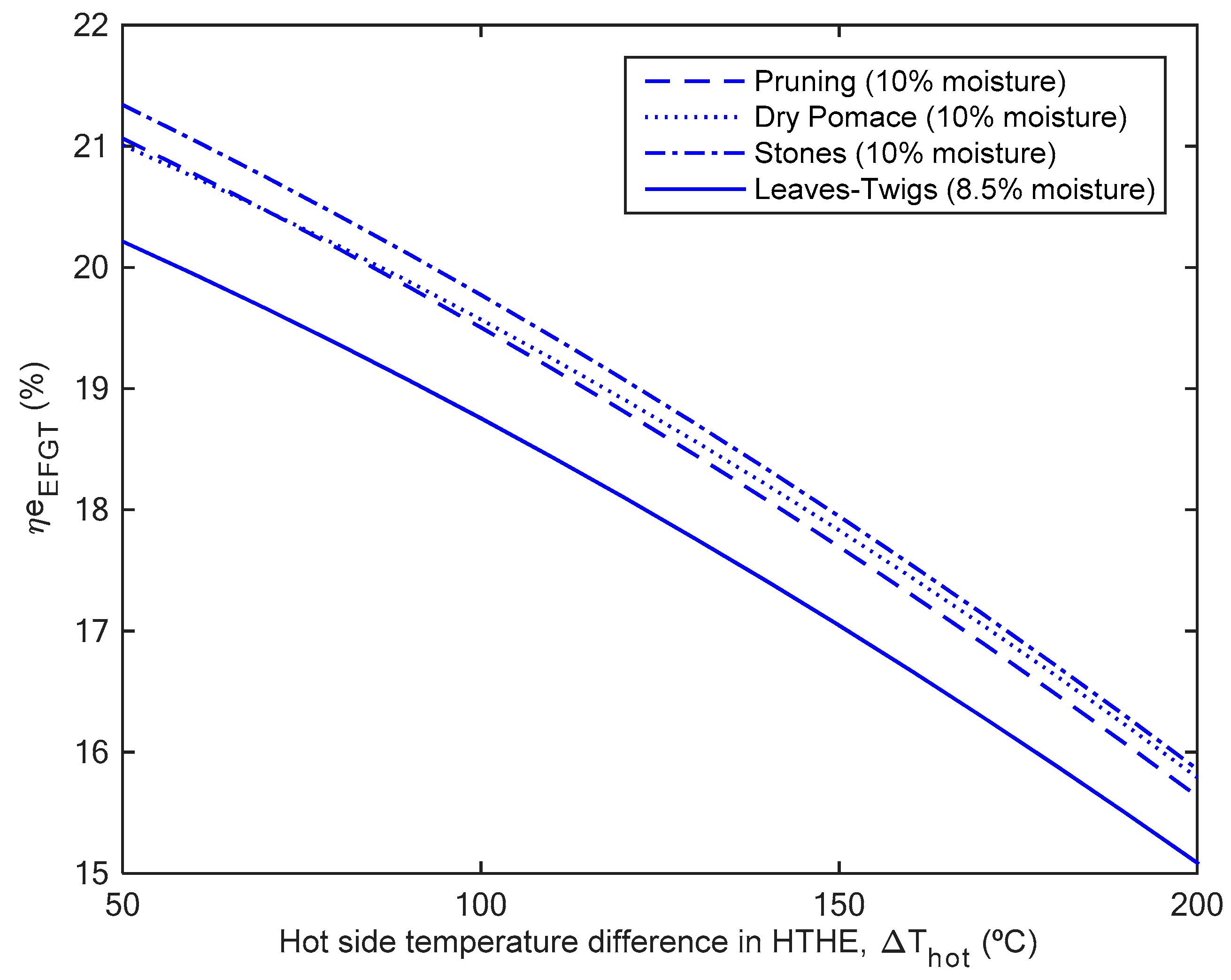
  • Olive industry wastes were burnt in an EFGT producing 400 kW of electric power and heat in the way of exhaust gases. The high temperature heat exchanger (HTHE) was the decisive component of this sub-system, and the optimum compressor pressure and TIT was achieved at 5 bars and 875 °C, respectively. The electric efficiency of the EFGT was 19% operating without the ORC generator.
  • For increasing the low electric efficiency of the EFGT, the flue gases at EFGT outlet were used in an ORC generator. The behavior of the ORC subsystem directly depended on the working fluid, pump pressure and TIT. A new working fluid, R1233zd, was selected as the optimum for the electric power maximization, producing 152.4 kW and 22.1% of ORC thermal efficiency. From environmental point of view, R1233zd presented the lowest global warming potential index (GWP = 2), very suitable compared with typical organic fluids as R245fa (GWP = 1030) and R113 (GWP = 6130). Moreover, R1233zd showed suitable safety information (no flammability and instability). As drawback, R1233zd was not able to produce thermal power due to its lower condensation temperature (18.3 °C according to Table 4), being only suitable for electric distributed generation.
  • Finally, despite R113 gave minor electricity production (137.5 kW) and ORC thermal efficiency (19.9%), this allowed generating thermal power for CHP applications (506.8 kW) in the way of hot water at 45 °C. Notice that in the concrete case of this work, the olive oil industry, this water flow can be very suitable for the olive oil production process. In contrast, R113 was not an eco-friendly organic fluid, presenting the highest GWP index among ten working fluids evaluated.
The EFGT-ORC hybrid system reached a net electrical efficiency of 26.0% (for R1233zd) and produced a total of 552.4 kW of electric power with a biomass consumption between 430–460 kg/h (roughly) for olive tree pruning, dry pomace and stones. The value of electric efficiency is higher than other similar works presented in the literature for the same biomass conversion technology. Finally, olive tree pruning, dry pomace and stones can be a good fuel for the correct operating of the hybrid system proposed; however, the use of leaves and twigs in biomass combustion chambers can be problematic due to their high ash content (8.71%).

Author Contributions

D.V. and B.d.M. implemented the system, performed the modelling and simulation, results and wrote this paper. J.C.-H. Hernández and F.J. assisted with the idea development and the paper writing.

Funding

This work was supported in part by Project entitled ‘‘Adaptation of renewable energy solutions for the olive oil industry” (RESOLIVE), Grant Agreement Number: 218453. This Project is funded by the European Commission within the Seventh Framework Programme (2007-2013).

Conflicts of Interest

The authors declare no conflict of interest.

References

  1. IOC World Olive Oil Figures. Available online: http://www.internationaloliveoil.org/estaticos/view/131-world-olive-oil-figures (accessed on 20 May 2016).
  2. García-Maraver, A.; Zamorano, M.; Ramos-Ridao, A.; Díaz, L.F. Analysis of olive grove residual biomass potential for electric and thermal energy generation in Andalusia (Spain). Renew. Sustain. Energy Rev. 2012, 16, 745–751. [Google Scholar] [CrossRef]
  3. Vera, D.; Jurado, F.; Margaritis, N.K.; Grammelis, P. Experimental and economic study of a gasification plant fuelled with olive industry wastes. Energy Sustain. Dev. 2014, 23, 247–257. [Google Scholar] [CrossRef]
  4. Malheiro, R.; Rodrigues, N.; Manzke, G.; Bento, A.; Pereira, J.A.; Casal, S. The use of olive leaves and tea extracts as effective antioxidants against the oxidation of soybean oil under microwave heating. Ind. Crop. Prod. 2013, 44, 37–43. [Google Scholar] [CrossRef]
  5. de Mena, B.; Vera, D.; Jurado, F.; Ortega, M. Updraft gasifier and ORC system for high ash content biomass: A modelling and simulation study. Fuel Process. Technol. 2017, 156, 394–406. [Google Scholar] [CrossRef]
  6. Pesta, G.; Mayer Pittroff, R.W. Utilization of By-Products and Treatment of Wast in the Food Industry; Springer: Luxemburg, 2007; ISBN 9780387335117. [Google Scholar]
  7. Evans, R. Optimization of a wood-waste-fuelled, indirectly fired gas turbine cogeneration plant. Bioresour. Technol. 1996, 57, 117–126. [Google Scholar] [CrossRef]
  8. Vera, D.; Jurado, F.; de Mena, B.; Schories, G. Comparison between externally fired gas turbine and gasifier-gas turbine system for the olive oil industry. Energy 2011, 36, 6720–6730. [Google Scholar] [CrossRef]
  9. Vera, D.; Jurado, F.; Carpio, J. Study of a downdraft gasifier and externally fired gas turbine for olive industry wastes. Fuel Process. Technol. 2011, 92, 1970–1979. [Google Scholar] [CrossRef]
  10. Al-attab, K.A.; Zainal, Z.A. Turbine startup methods for externally fired micro gas turbine (EFMGT) system using biomass fuels. Appl. Energy 2010, 87, 1336–1341. [Google Scholar] [CrossRef]
  11. Al-attab, K.A.; Zainal, Z.A. Performance of high-temperature heat exchangers in biomass fuel powered externally fired gas turbine systems. Renew. Energy 2010, 35, 913–920. [Google Scholar] [CrossRef]
  12. Al-attab, K.A.; Zainal, Z.A. Externally fired gas turbine technology: A review. Appl. Energy 2015, 138, 474–487. [Google Scholar] [CrossRef]
  13. Peris, B.; Navarro-Esbrí, J.; Molés, F.; Collado, R.; Mota-Babiloni, A. Performance evaluation of an Organic Rankine Cycle (ORC) for power applications from low grade heat sources. Appl. Therm. Eng. 2015, 75, 763–769. [Google Scholar] [CrossRef]
  14. Peris, B.; Navarro-Esbrí, J.; Molés, F.; Mota-Babiloni, A. Experimental study of an ORC (organic Rankine cycle) for low grade waste heat recovery in a ceramic industry. Energy 2015, 85, 534–542. [Google Scholar] [CrossRef]
  15. Huang, B.S.; Chen, H.Y.; Kuo, J.H.; Chang, C.H.; Wey, M.Y. Catalytic upgrading of syngas from fluidized bed air gasification of sawdust. Bioresour. Technol. 2012, 110, 670–675. [Google Scholar] [CrossRef] [PubMed]
  16. Invernizzi, C.; Iora, P.; Silva, P. Bottoming micro-Rankine cycles for micro-gas turbines. Appl. Therm. Eng. 2007, 27, 100–110. [Google Scholar] [CrossRef]
  17. Camporeale, S.M.; Pantaleo, A.M.; Ciliberti, P.D.; Fortunato, B. Cycle configuration analysis and techno-economic sensitivity of biomass externally fired gas turbine with bottoming ORC. Energy Convers. Manag. 2015, 105, 1239–1250. [Google Scholar] [CrossRef]
  18. Iora, P.; Silva, P. Innovative combined heat and power system based on a double shaft intercooled externally fired gas cycle. Appl. Energy 2013, 105, 108–115. [Google Scholar] [CrossRef]
  19. Vera, D.; Jurado, F.; Carpio, J.; Kamel, S. Biomass gasification coupled to an EFGT-ORC combined system to maximize the electrical energy generation: A case applied to the olive oil industry. Energy 2018, 144, 41–53. [Google Scholar] [CrossRef]
  20. Vera, D.; Jurado, F.; Panopoulos, K.D.; Grammelis, P. Modelling of biomass gasifier and microturbine for the olive oil industry. Int. J. Energy Res. 2012, 36, 355–367. [Google Scholar] [CrossRef]
  21. De Mello, P.E.B.; Monteiro, D.B. Thermodynamic study of an EFGT (externally fired gas turbine) cycle with one detailed model for the ceramic heat exchanger. Energy 2012, 45, 497–502. [Google Scholar] [CrossRef]
  22. Cocco, D.; Deiana, P.; Cau, G. Performance evaluation of small size externally fired gas turbine (EFGT) power plants integrated with direct biomass dryers. Energy 2006, 31, 1459–1471. [Google Scholar] [CrossRef]
  23. Bao, J.; Zhao, L. A review of working fluid and expander selections for organic Rankine cycle. Renew. Sustain. Energy Rev. 2013, 24, 325–342. [Google Scholar] [CrossRef]
  24. Rahbar, K.; Mahmoud, S.; Al-Dadah, R.K.; Moazami, N.; Mirhadizadeh, S.A. Review of organic Rankine cycle for small-scale applications. Energy Convers. Manag. 2017, 134, 135–155. [Google Scholar] [CrossRef]
  25. Drescher, U.; Brüggemann, D. Fluid selection for the Organic Rankine Cycle (ORC) in biomass power and heat plants. Appl. Therm. Eng. 2007, 27, 223–228. [Google Scholar] [CrossRef]
  26. Macchi, E. 1 – Theoretical basis of the Organic Rankine Cycle. In Organic Rankine Cycle (ORC) Power Systems; Woodhead Publ. Ltd.: Cambridge, UK; Abington Hall: Abington, PA, USA, 2017; pp. 3–24. ISBN 9780081005101. [Google Scholar]
  27. Astolfi, M.; Martelli, E.; Pierobon, L. 7 – Thermodynamic and technoeconomic optimization of Organic Rankine Cycle systems. In Organic Rankine Cycle (ORC) Power Systems; Woodhead Publ. Ltd.: Cambridge, UK; Abington Hall: Abington, PA, USA, 2017; pp. 173–249. ISBN 9780081005101. [Google Scholar]
  28. Mohammadi, A.; Kasaeian, A.; Pourfayaz, F.; Ahmadi, M.H. Thermodynamic analysis of a combined gas turbine, ORC cycle and absorption refrigeration for a CCHP system. Appl. Therm. Eng. 2017, 111, 397–406. [Google Scholar] [CrossRef]
  29. Branchini, L.; De Pascale, A.; Peretto, A. Systematic comparison of ORC configurations by means of comprehensive performance indexes. Appl. Therm. Eng. 2013, 61, 129–140. [Google Scholar] [CrossRef]
  30. Eksi, G.; Karaosmanoglu, F. Combined bioheat and biopower: A technology review and an assessment for Turkey. Renew. Sustain. Energy Rev. 2017, 73, 1313–1332. [Google Scholar] [CrossRef]
  31. Nunes, L.J.R.; Matias, J.C.O.; Catalão, J.P.S. Biomass in the generation of electricity in Portugal: A review. Renew. Sustain. Energy Rev. 2017, 71, 373–378. [Google Scholar] [CrossRef]
  32. Datta, A.; Ganguly, R.; Sarkar, L. Energy and exergy analyses of an externally fired gas turbine (EFGT) cycle integrated with biomass gasifier for distributed power generation. Energy 2010, 35, 341–350. [Google Scholar] [CrossRef]
  33. García-Maraver, A.; Terron, L.C.; Ramos-Ridao, A.; Zamorano, M. Effects of mineral contamination on the ash content of olive tree residual biomass. Biosyst. Eng. 2014, 118, 167–173. [Google Scholar] [CrossRef]
Figure 1. By-products during the olive oil industry value chain (Spanish 2-phase extraction process).
Energies 12 00500 g001
Figure 2. Sample of olive tree pruning (top-left), olive pits (top-right), dry olive pomace (bottom-left) and leaves and twigs (bottom-right).
Energies 12 00500 g002aEnergies 12 00500 g002b
Figure 3. Layout of the hybrid EFGT-ORC power plant.
Energies 12 00500 g003
Figure 4. Cycle-Tempo® layout of the EFGT-ORC system fueled with olive tree pruning and R1233zd as ORC working fluid.
Energies 12 00500 g004
Figure 5. EFGT electrical efficiency ( η e E F G T ) with the compressor pressure at different TITs (olive tree pruning biomass).
Energies 12 00500 g005
Figure 6. Influence of the hot side temperature difference of the HTHE (ΔThot) in the η e E F G T for the different biomasses proposed.
Energies 12 00500 g006
Figure 7. ORC electric power ( P e O R C ) and thermal efficiency (ηORC) for the working fluids studied.
Energies 12 00500 g007
Table 1. Main properties and current applications of the olive oil industry by-products.
By-ProductOlive Tree PruningOlive PitsOlive Pomace (2-Phases)Leaves, Twigs
LocationOlive groveOlive millOlive millOlive mill
Production rate2.5–3.0 t/ha90–100 kg/t of olives650–750 kg/t of olives80–100 kg/t of olives
Ash (%, ar)3–50.5–22–58–10
Moisture (%, ar)10–2020–3565–705–10
Lower Calorific Value, LHV (MJ/kg, db)16–1817–1916–1810–14
Selling price (€/kg)Free0.08 (wet)Disposal feeFree
Current valorizationNone (burn or scattered in the field)Sold to biomass tradersPomace oil, extractor companiesNone
Table 2. Proximate and elemental analyses of the olive industry wastes.
Proximate Analysis (% Weight)StonesLeaves and TwigsOlive Tree PruningPomace (2 Phases)
Moisture (ar)25–308.510–1565–70
Ashes (db)1–28.713–52–5
Volatiles (db)76.3671.4178.1877.38
Fixed carbon (db)21.5819.8817.1317.60
Elemental analysis (% weight, dry basis)
C50.0845.0847.1051.31
H5.905.896.186.40
N0.640.520.552.00
S0.020.090.100.26
O (difference)41.0339.7041.6635.01
Other properties
LHV (MJ/kg)17.912.316.317.0
Ash melting point (°C)>1200>1200>1200>1200
Bulk density (kg/m3)
Average particle size (mm)
709
2–5
108
20–40
195
20–60
780
5–10
Table 3. Performance parameters of the EFGT sub-system.
ParameterUnitValue
Combustion chamber pressurebar1.013
Combustion chamber efficiency%94
Combustion chamber pressure drop%1
Maximum flue gases temperature°C1000
HTHE thermal efficiency%85
HTHE pressure drop%2
Hot side temperature difference for HTHE°C125
Maximum turbine inlet temperature (TIT)°C875
Turbine isentropic efficiency%83
Compressor isentropic efficiency%80
Turbine and compressor mechanical efficiency%95
Electric generator efficiency%96
Exhaust gases temperature°C300
Table 4. Physical and environmental properties of the suitable working fluids.
Working FluidMolar Mass (kg/kmol)Critical Pressure (Bar)Critical Temp. (°C)Maximum Operative Temp. (°C)Condensation Temperature (°C)Environmental Issues b
GWP aHFI
Cyclohexane84.1640.7280426.980.34–6130
Isohexane86.1830.422527760.24–6230
Pentane72.1533.719740036.24–6140
Isopentane72.1533.818722726.84–6140
Neopentane72.1532.01612779.54–6140
R113187.3833.821425147.46130110
R245fa134.0536.515422614.81030210
R365mfc148.0732.718722640.2794041
R1233zd130.5036.2166.4527718.31200
Methanol32.0482.224035078.24–6130
a GWP: Global Warming Potential index. b Safety information according to NFPA classification: H, Healt; F, Flammability; I, Instability. Each index range from 0-no hazard to 4-maximum hazard.
Table 5. Performance parameters and technical constraints in the ORC model.
Performance ParameterUnitValue
Turbine isentropic efficiency%80
Turbine mechanical efficiency%95
Pump isentropic efficiency%75
Pump electro-mechanical efficiency%85
Regenerator and evaporator efficiency%85
Condenser efficiency%87
Electric generator efficiency%97
Pressure drop in evaporator%2
Pressure drop in regenerator%1
Technical constraintsUnitValue
Minimum stack temperature°C100
Minimum evaporator pinch point temperature, ΔTpinch°C10
Heat source temperature °C300
Maximum pump operating pressurebar25
Table 6. Optimum operating conditions of the EFGT for different olive industry wastes and 400 kW of nominal electric power.
Olive Industry WasteExhaust Gases Mass Flow mfg (kg/s)Exhaust Gases Temperature (°C)Biomass Mass Flow mb (kg/h) η e E F G T (%)
Pruning4.03299.5464.419.03
Dry pomace4.07300.7450.019.05
Stones4.03300.3428.418.95
Leaves and twins4.06303.6633.618.48
Table 7. Optimum operating conditions for the ORC working fluids selected.
Working Fluid P p O R C   ( Bar ) TIT (°C) m ˙ O R C   ( kg / s ) W p u m p   ( kW ) P e O R C   ( kW ) P t O R C   ( kW ) η O R C (%)
Cyclohexane132001.33.293.6475.7 a15.60
Isohexane252401.247.6115.8423.4 b18.82
Pentane252401.217.2138.2-20.02
Isopentane251771.559.0142.4-20.80
Neopentane252401.197.4140.7-20.41
R113252303.357.9137.5506.8 c19.92
R245fa252162.346.3138.3-19.90
R365mfc252162.577.9135.4481.4 d19.30
R1233zd252602.286.7152.4-22.05
Methanol252100.623.493.6461.2 a15.82
a: based on hot water at 70 °C; b: hot water at 50 °C, c: hot water at 45 °C, d: hot water at 38 °C.
Table 8. Analyses and comparison of the ORC performance indexes.
Hot Source Working FluidPresent WorkBranchini et al. [29]
THOT = 300 °CTHOT = 400 °CTHOT = 200 °C
R1233zdR113IsopentaneMDMTolueneR245faButane
Type of cycleREC + SHRECsCREC + SHSH
Pv (bar)25.025.025.013.739.027.330.3
ηORC (%)22.119.920.822.224.516.314.4
WORC (kJ/kg)674192691843875
VER (-)21.426.130.0624.01199.020.015.0
MFR (-)0.5660.8310.3850.7160.4880.5390.289
∑UA (kJ/kg °C)35.417.815.013.618.114.813.2
UAREC0.70.91.93.8-1.3-
UACON27.810.510.34.25.15.94.0
UAEVA6.96.42.80.20.41.91.9
UAECO---5.412.55.57.1
UASH-----0.20.2
REC: Recuperated cycle; SH: Superheated cycle; sC: simple cycle [29].
Table 9. Optimum results reached in this work compared with two EFGT-ORC systems published in the literature.
Performance Parameters UnitPresent WorkVera et al. [19]Camporeale et al. [17]
Biomass conversion technology-External combustionDowndraft gasifierFurnace
Type of biomass-Olive industry wastesOlive tree pruningn.a.
Biomass consumptionKg/h430–4602173600
EFGT electric powerkW400.0150.21383.0
ORC electric powerkW152.4 (R1233zd)
137.5 (R113)
57.1 (isopentane)
49.1 (R113)
700
Thermal power availablekW506.8 (R113)199.8 (R113)963
Waste source temperature°C300290400
Optimum ORC working fluids-R1233zd (electricity)
R113 (CHP)
Isopentane (electricity)
R113 (CHP)
Toluene (CHP)
ORC thermal efficiency%22.1 (R1233zd)
19.9 (R113)
20.5 (isopentane)
17.6 (R113)
19.0
Net electric efficiency%26.0 (R1233zd)
25.2 (R113)
20.7 (isopentane)
20.0 (R113)
23.0
Percentage of electric power increased%38.138.050.5

