Research on Configuration Methods of Battery Energy Storage System for Pure Electric Bus Fast Charging Station

Abstract
1. Introduction
- Charging topology: the possible configuration allocations and the size of a single BESS must be determined.
- Integration points of the BESS: the charge-discharge power and energy loss are dependent on this factor.
- Related influence factors: the model will be more accurate if more aspects are considered.
2. Scenarios of BESS Configuration
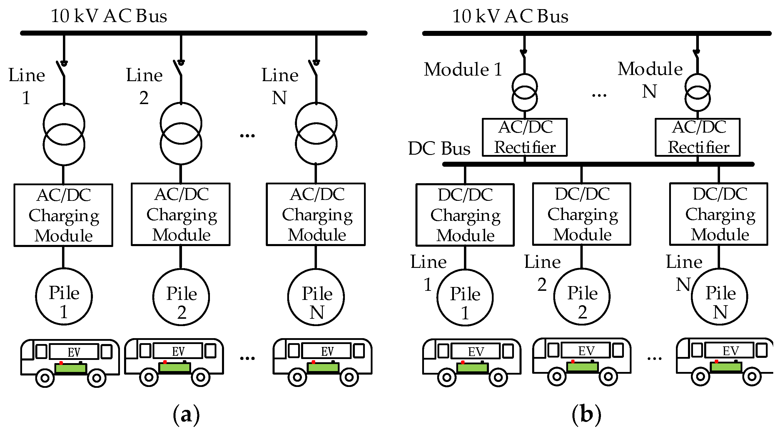
2.1. Charging Topologies
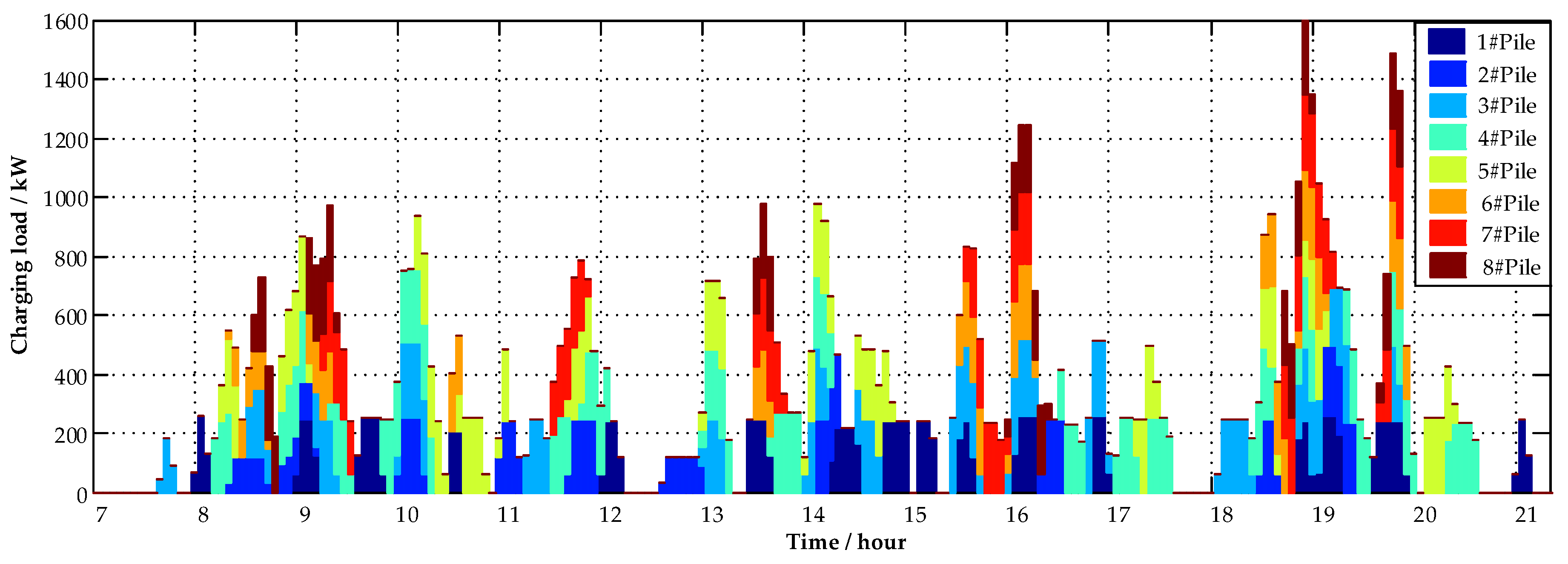
2.2. Charging Load Charateristics
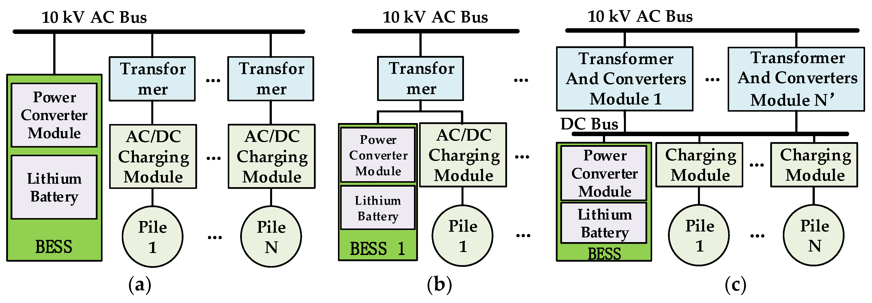
2.3. BESS Configuration Strategies
3. BESS Configuration Model
3.1. Models of Influence Factors
- (1)
- Basic electricity cost:where is the cost of basic electricity, which is composed of the basic electricity price and peak charging power of the PEB fast-charging station.
- (2)
- Charging electricity cost:where is the electricity consumption at time , and is the electricity cost of the charging station. is the time-of-use electricity tariff at time .
- (3)
- Investment of transformer and converters:where and are the translated daily investment of transformers and converters, respectively, of the charging topology during the entire lifetime [24].
- (4)
- Energy conversion loss:where , and are the electric energy losses during the charging process of the three BESS configuration scenarios. , , and are the efficiency of the transformer, AC/DC conversion, BESS charging, and discharging, respectively.
- (5)
- Full lifetime cost of BESS. For the BESS, the energy capacity and charge-discharge power are the two key parameters affecting the cost [25]. The cycle lifetime of battery was introduce to the BESS cost model in [22], the new formulation of BESS full lifetime cost is as follows:where is the full lifetime cost of the BESS, and and are the translated daily BESS battery costs and connected converter costs for the estimated lifetime in accordance with the initial investment. and are the number of the BESSs charging and discharging per day, respectively. Those variables are also used to calculate the cycle lifetime of the BESS. is the calendar lifetime of the BESS. is the total power of the BESS in different scenarios at time . Comparing the calendar lifetime and cycle lifetime, the minor value should be used in the cost calculation.
3.2. Objective Functions
3.3. Model Constraints
- (1)
- Total power balance:where is the power from the grid at time ; , , and are the BESS power of configuration scenario 1, 2, and 3, respectively, at time ; charging power is indicated by +; discharging power is indicated by −; is the charging power of charging pile at ; and is the period of [ − 1,].
- (2)
- BESS energy balance: In order to achieve a sustainable operation of the BESS, the charging energy should match the discharging energy at the end of each operation cycle:
- (3)
- Safety SOC range of BESS: During the BESS operational procedure, the SOC of the BESS should be constrained to a suitable range, called the depth of discharge (DOD), to keep the BESS working well. This also decides the total discharging and charging energy of the BESS [27]. For example, the SOC range of the BESS is 20–90%, which means that the DOD is 70%. The formulation of SOC is as follows:where is the state of energy of the battery at , is the discharge efficiency, and is the charge efficiency.
- (4)
- Charge-discharge rate of BESS: The charge-discharge rate of the BESS is the ratio of the charge-discharge current and the capacity of the BESS, and it determines the BESS’s maximum charging and discharging power. In this paper, the charge-discharge rate is the ratio of power and BESS energy, which is limited to a set value to maintain the lifetime and safety of the batteries:
- (5)
- Node power direction: As the BESS is integrated according to a charging topology, the node power with BESS discharging power will change. In order to prevent reverse power flow, the total power demand of the nodes should not be less than the discharging power of the BESS of the nodes:
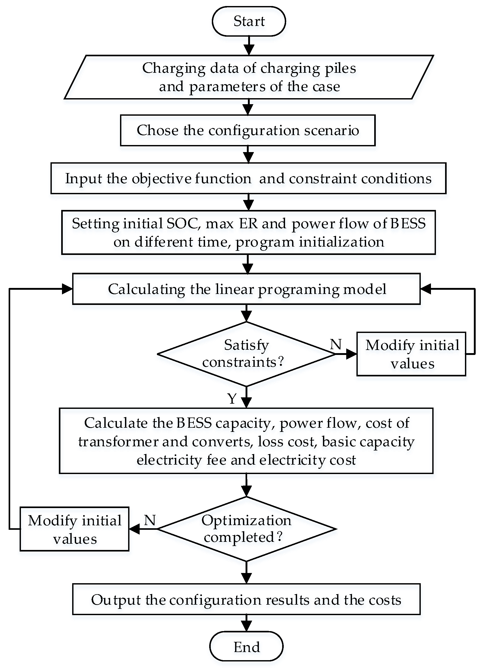
3.4. Optimization Algorithum and Steps
- Step 1:
- Set the simulation cycle time to 24 h; set the sampling period, , on the basis of optimized time interval, which can decide the number of samples, ; take the energy of the BESS at each sample time as the variable, .
- Step 2:
- Calculate the power of the BESS of each sample spot on the basis of the sample cycle as ; the positive value means charge, and a negative value means discharge.
- Step 3:
- According to the maximum DOD, calculate the energy and power of the BESS, as shown in Equations (23) and (24):
4. Cases and Analysis
4.1. Case Settings
4.2. Optimization Configuration
4.3. Case Analysis
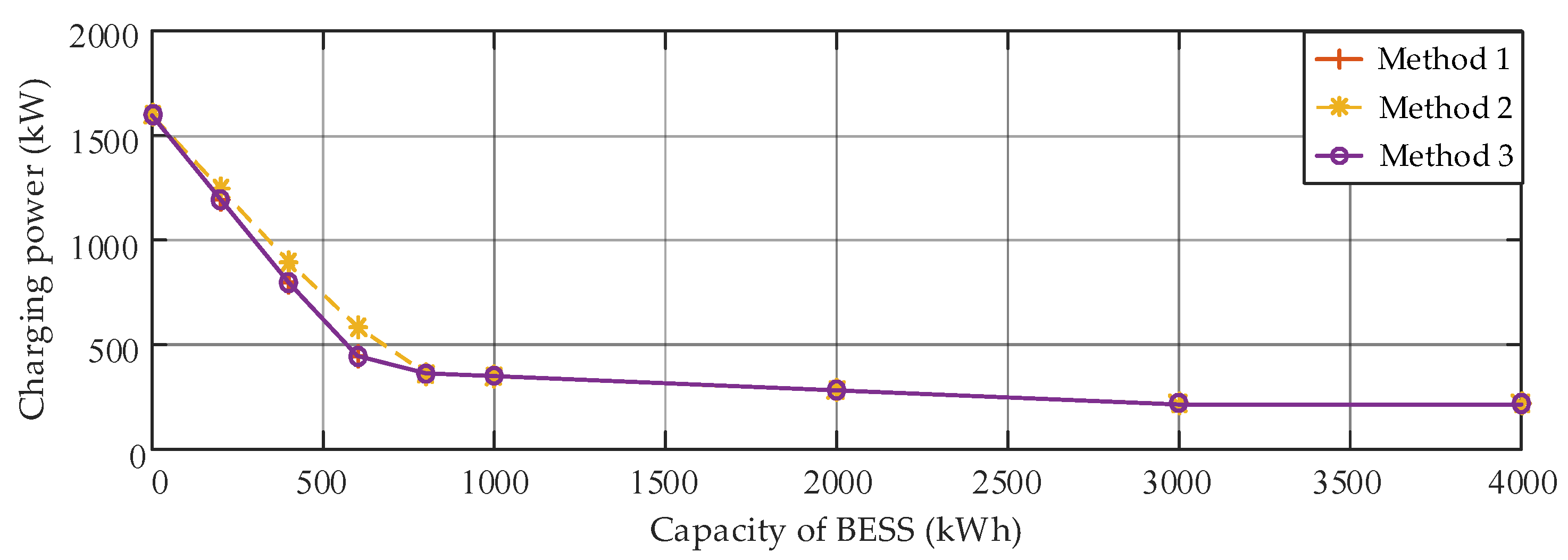
4.3.1. Basic Electricity Analysis
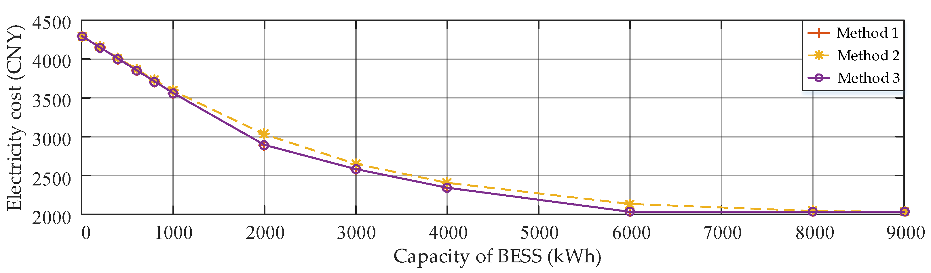
4.3.2. Charging Electricity Analysis
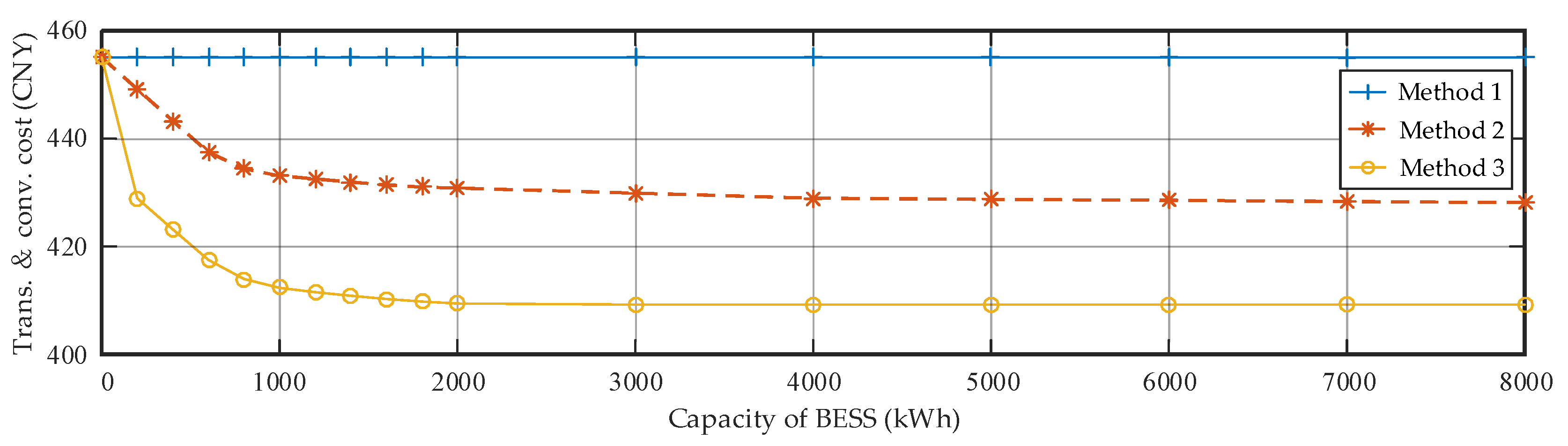
4.3.3. Transformer and Converter Cost Analysis
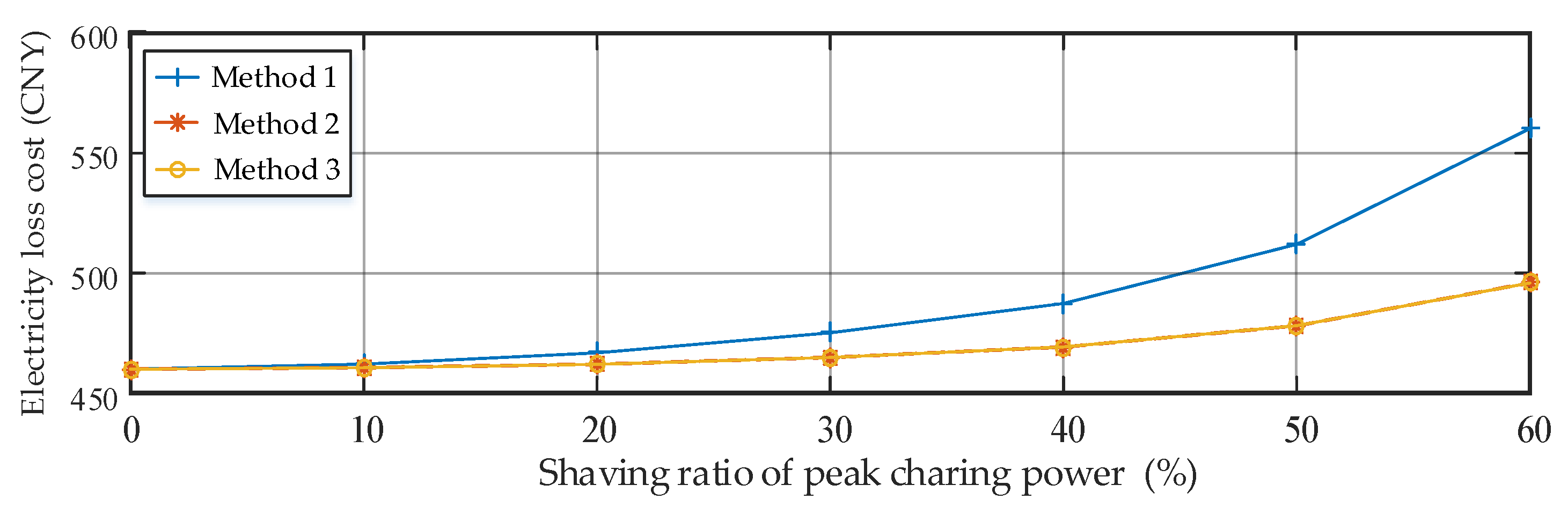
4.3.4. Electricity Loss Cost Analysis
4.4. Conclusion of Case Analysis
5. Discussion
- (1)
- The BESS is an available component to suppress the distribution capacity demand of the high-power PEB fast charging station from an economic perspective. The investment of the BESS can be recouped, and it leads to considerable benefits, such as a decrease in the basic electricity fee and the income gained from the TOU tariffs.
- (2)
- The economic model considers the basic electricity, charging electricity, charging equipment, electricity loss, and BESS investment to cover the main factors of a BESS configuration in a PEB fast charging station. However, the results are related to the charging topology and the amount of charging electricity. The economic effects may significantly differ depending on the applied scenario. The model can be used to choose the charging topology and BESS integration point.
- (3)
- The costs of basic electricity and charging electricity are the two main factors that can lead to cost savings. The electricity loss in different topologies is a main part of the total cost, but it has a few differences among the various topologies. Also, the investment of the BESS and charging equipment is obviously different among the scenarios. According to the case in this paper, the charging topology and BESS integration point are the two key aspects that influence the overall economics.
6. Conclusions
Author Contributions
Funding
Conflicts of Interest
References
- Deb, S.; Tammi, K.; Kalita, K.; Mahanta, P. Review of recent trends in charging infrastructure planning for electric vehicles. Wiley Interdiscip. Rev.: Energy Environ. 2018, 7, e306. [Google Scholar] [CrossRef]
- Hu, X.; Johannesson, L.; Murgovski, N.; Egardt, B. Longevity-conscious dimensioning and power management of the hybrid energy storage system in a fuel cell hybrid electric bus. Appl. Energy 2015, 137, 913–924. [Google Scholar] [CrossRef]
- Chung, W.; Zhou, G.; Yeung, I.M.H. A study of energy efficiency of transport sector in China from 2003 to 2009. Appl. Energy 2013, 112, 1066–1077. [Google Scholar] [CrossRef]
- Bao, Y.; Luo, Y.; Zhang, W.; Huang, M.; Wang, L.; Jiang, J. A Bi-Level Optimization Approach to Charging Load Regulation of Electric Vehicle Fast Charging Stations Based on a Battery Energy Storage System. Energies 2018, 11, 229. [Google Scholar] [CrossRef]
- Serradilla, J.; Wardle, J.; Blythe, P.; Gibbon, J. An evidence-based approach for investment in rapid-charging infrastructure. Energy Policy 2017, 106, 514–524. [Google Scholar] [CrossRef]
- Xylia, M.; Leduc, S.; Patrizio, P.; Kraxner, F.; Silveira, S. Locating charging infrastructure for electric buses in Stockholm. Transp. Res. Part C Emerg. Technol. 2017, 78, 183–200. [Google Scholar] [CrossRef]
- Bryden, T.S.; Hilton, G.; Cruden, A.; Holton, T. Electric vehicle fast charging station usage and power requirements. Energy 2018, 152, 322–332. [Google Scholar] [CrossRef]
- Grackova, L.; Oleinikova, I. Impact of Electric Vehicle Charging on the Urban Distribution Network. In Proceedings of the 57th International Scientific Conference on Power and Electrical Engineering of Riga Technical University (RTUCON), Riga, Latvia, 13–14 October 2016. [Google Scholar]
- Deb, S.; Tammi, K.; Kalita, K.; Mahanta, P. Impact of Electric Vehicle Charging Station Load on Distribution Network. Energies 2018, 11, 178. [Google Scholar] [CrossRef]
- Leou, R.; Hung, J. Optimal Charging Schedule Planning and Economic Analysis for Electric Bus Charging Stations. Energies 2017, 10, 483. [Google Scholar] [CrossRef]
- Zhang, W.; Ge, W.; Huang, M.; Jiang, J. Optimal Day-Time Charging Strategies for Electric Vehicles considering Photovoltaic Power System and Distribution Grid Constraints. Math Probl. Eng. 2015, 2015, 1–9. [Google Scholar] [CrossRef]
- Yang, Y.; Zhang, W.; Niu, L.; Jiang, J. Coordinated charging strategy for electric taxis in temporal and spatial scale. Energies 2015, 8, 1256–1272. [Google Scholar] [CrossRef]
- Liao, J.T.; Lin, C.I.; Chien, C.Y.; Yang, H.T. The distributed energy resources operation for EV charging stations and SHEMS in microgrids. In Proceedings of the 2014 International Conference on Intelligent Green Building and Smart Grid (IGBSG), Taipei, Taiwan, 23–25 April 2014; pp. 1–6. [Google Scholar]
- Zhang, W.; Zhang, D.; Mu, B.; Wang, L.; Bao, Y.; Jiang, J.; Morais, H. Decentralized Electric Vehicle Charging Strategies for Reduced Load Variation and Guaranteed Charge Completion in Regional Distribution Grids. Energies 2017, 10, 147. [Google Scholar] [CrossRef]
- Yan, B.; Xue, S.; Li, Y.; Duan, J.; Zeng, M. Gas-fired combined cooling, heating and power (CCHP) in Beijing: A techno-economic analysis. Renew. Sust. Energy Rev. 2016, 63, 118–131. [Google Scholar] [CrossRef]
- Makohin, D.; Jordan, F.V.; Zeni, V.S.; Lemos, K.H.M.; Pica, C.; Gianesini, M.A. Use of Lithium Iron Phosphate Energy Storage System for EV Charging Station Demand Side Management. In Proceedings of the 8th IEEE International Symposium on Power Electronics for Distributed Generation Systems, Florianópolis, Brazil, 17–20 April 2017; pp. 1–6. [Google Scholar]
- Deng, J.; Shi, J.; Liu, Y.; Tang, Y. Application of a hybrid energy storage system in the fast charging station of electric vehicles. IET Gener. Transm. Distrib. 2016, 10, 1092–1097. [Google Scholar] [CrossRef]
- Rivera, S.; Wu, B.; Kouro, S.; Yaramasu, V.; Wang, J. Electric Vehicle Charging Station Using a Neutral Point Clamped Converter With Bipolar DC Bus. IEEE Trans. Ind. Electron. 2015, 62, 1999–2009. [Google Scholar] [CrossRef]
- Negarestani, S.; Fotuhi-Firuzabad, M.; Rastegar, M.; Rajabi-Ghahnavieh, A. Optimal Sizing of Storage System in a Fast Charging Station for Plug-in Hybrid Electric Vehicles. IEEE Trans. Transp. Electrif. 2016, 2, 443–453. [Google Scholar] [CrossRef]
- Yan, Y.; Jiang, J.; Zhang, W.; Huang, M.; Chen, Q.; Wang, H. Research on Power Demand Suppression Based on Charging Optimization and BESS Configuration for Fast-Charging Stations in Beijing. Appl. Sci. 2018, 8, 1212. [Google Scholar] [CrossRef]
- Martinsen, T. A business model for an EV charging station with battery energy storage. In Proceedings of the CIRED Workshop 2016, Helsinki, Finland, 14–15 June 2016; pp. 1–4. [Google Scholar]
- Ding, H.; Hu, Z.; Song, Y. Value of the energy storage system in an electric bus fast charging station. Appl. Energy 2015, 157, 630–639. [Google Scholar] [CrossRef]
- McPhail, D. Evaluation of ground energy storage assisted electric vehicle DC fast charger for demand charge reduction and providing demand response. Renew. Energy 2014, 67, 103–108. [Google Scholar] [CrossRef]
- Madina, C.; Zamora, I.; Zabala, E. Methodology for assessing electric vehicle charging infrastructure business models. Energy Policy 2016, 89, 284–293. [Google Scholar] [CrossRef]
- Nguyen, C.L.; Chun, T.W.; Lee, H.H. Determination of the optimal battery capacity based on a life time cost function in wind farm. In Proceedings of the 2013 IEEE Energy Conversion Congress and Exposition, Denver, CO, USA, 15–19 September 2013; pp. 51–58. [Google Scholar]
- Rivera, S.; Wu, B. Electric Vehicle Charging Station with an Energy Storage Stage for Split-DC Bus Voltage Balancing. IEEE Trans. Power Electr. 2017, 32, 2376–2386. [Google Scholar] [CrossRef]
- Kim, K.; Yoon, T.; Byeon, G.; Jung, H. Power demand and power quality analysis of EV charging station using BESS in MicroGrid. In Proceedings of the 2012 IEEE Vehicle Power and Propulsion Conference, Seoul, Korea, 9–12 October 2012; pp. 996–1001. [Google Scholar]
- Anseán, D.; González, M.; Viera, J.C.; García, V.M.; Blanco, C.; Valledor, M. Fast charging technique for high power lithium iron phosphate batteries: A cycle life analysis. J. Power Sources 2013, 239, 9–15. [Google Scholar] [CrossRef]
- Gao, Y.; Jiang, J.; Zhang, C.; Zhang, W.; Ma, Z.; Jiang, Y. Lithium-ion battery aging mechanisms and life model under different charging stresses. J. Power Sources 2017, 356, 103–114. [Google Scholar] [CrossRef]


| Symbol | Explanation |
|---|---|
| Ratio of operation and maintenance cost of the transformer | |
| Ratio of operation and maintenance cost of the converters | |
| Ratio of operation and maintenance cost of the batteries | |
| Cost of the BESS’s unit battery energy | |
| Cost of the BESS’s unit converter power | |
| Rated capacity of BESS | |
| Rated power of BESS | |
| Discount rate | |
| Total charging power of BESS at time | |
| Total number of charge-discharge cycles of BESS | |
| Minimum state of charge (SOC) of BESS | |
| Maximum SOC of BESS | |
| Charging power of BESS at time | |
| Discharging power of BESS at time | |
| Maximum discharging power of BESS | |
| Maximum charging power of BESS | |
| Number of samples for BESS configuration simulation | |
| Sampling period for BESS configuration simulation | |
| Number of daily optimization intervals | |
| Energy of BESS at each time of the sample |
| Parameter | Value |
|---|---|
| Transformer cost (USD/kVA) | 11.89 |
| Basic electricity price (USD/(kVA·month)) | 4.75 |
| Lithium-ion battery cost (USD/kWh) | 222.88 |
| Converter cost (USD/kW) | 74.29 |
| Transformer lifetime (Year) | 20 |
| BESS calendar lifetime (Year) | 8 |
| Cycle number of the battery | 4500 |
| Max charge-discharge rate (C) | 2 |
| Discount rate (%) | 3 |
| SOC range of the BESS (%) | 10–90 |
| Efficiency of transformer (%) | 98 |
| Efficiency of converter (%) | 95 |
| Efficiency of charge–discharge of the BESS (%) | 95 |
| Period | Time | Price (USD/kWh) |
|---|---|---|
| Village | 23:00–7:00 | 0.0586 |
| Flat | 7:00–10:00; 15:00–18:00 21:00–23:00 | 0.1033 |
| Peak | 10:00–15:00; 18:00–21:00 | 0.1492 |
| Parameter | Scenario 1 | Scenario 2 | Scenario 3 |
|---|---|---|---|
| Unit electricity cost (USD/kWh·day) | 0.1748 | 0.1668 | 0.1667 |
| Total cost of one day (USD/day) | 899.48 | 858.05 | 857.73 |
| Peak charging power (kW) | 492.91 | 520.01 | 525.89 |
| Capacity of BESS (kWh) | 612.17 | 765.13 | 797.96 |
| Basic electricity cost (USD/day) | 78.13 | 82.42 | 83.35 |
| Electricity cost (USD/day) | 573.99 | 558.53 | 554.52 |
| Transformer and converter cost (USD/day) | 67.00 | 36.68 | 37.06 |
| Electricity loss cost (USD/day) | 95.15 | 81.88 | 82.14 |
| BESS cost (USD/day) | 85.22 | 98.85 | 100.66 |
| Parameter | Original | Scenario 1 | Scenario 2 | Scenario 3 |
|---|---|---|---|---|
| Peak charging power (kW) | 1595.00 | 464.98 | 370.56 | 464.98 |
| Basic electricity cost (USD/day) | 252.64 | 73.70 | 58.73 | 73.70 |
| Basic electricity and BESS cost (USD/day) | 252.64 | 155.62 | 166.53 | 155.62 |
| Capacity of BESS (kWh) | 0 | 565.01 | 743.47 | 565.01 |
| Parameter | Original | Scenario 1 | Scenario 2 | Scenario 3 |
|---|---|---|---|---|
| Electricity and BESS cost (CNY/day) | 638.68 | 628.00 | 638.68 | 628.00 |
| Electricity cost (CNY/day) | 638.68 | 515.90 | 638.68 | 515.90 |
| BESS capacity (kWh) | 0.00 | 1123.69 | 0.00 | 1123.69 |
| Peak charging power (kW) | 1595.00 | 1464.18 | 1595.00 | 1464.18 |
| Parameter | Scenario 1 | Scenario 2 | Scenario 3 |
|---|---|---|---|
| Basic electricity cost | Good | Bad | Good |
| Electricity cost | Good | Bad | Good |
| Transformer and converter cost | Bad | Moderate | Good |
| Electricity loss cost | Bad | Good | Good |
© 2019 by the authors. Licensee MDPI, Basel, Switzerland. This article is an open access article distributed under the terms and conditions of the Creative Commons Attribution (CC BY) license (http://creativecommons.org/licenses/by/4.0/).
Share and Cite
Yan, Y.; Wang, H.; Jiang, J.; Zhang, W.; Bao, Y.; Huang, M. Research on Configuration Methods of Battery Energy Storage System for Pure Electric Bus Fast Charging Station. Energies 2019, 12, 558. https://doi.org/10.3390/en12030558
Yan Y, Wang H, Jiang J, Zhang W, Bao Y, Huang M. Research on Configuration Methods of Battery Energy Storage System for Pure Electric Bus Fast Charging Station. Energies. 2019; 12(3):558. https://doi.org/10.3390/en12030558
Chicago/Turabian StyleYan, Yian, Huang Wang, Jiuchun Jiang, Weige Zhang, Yan Bao, and Mei Huang. 2019. "Research on Configuration Methods of Battery Energy Storage System for Pure Electric Bus Fast Charging Station" Energies 12, no. 3: 558. https://doi.org/10.3390/en12030558
APA StyleYan, Y., Wang, H., Jiang, J., Zhang, W., Bao, Y., & Huang, M. (2019). Research on Configuration Methods of Battery Energy Storage System for Pure Electric Bus Fast Charging Station. Energies, 12(3), 558. https://doi.org/10.3390/en12030558