1. Introduction
Finned-tube heat exchangers are widely used for heat exchange between air and liquids. Normally, the thermal resistance on the airside is dominant in the overall heat transfer process. Hence, more fin surface is often needed to ease the gigantic thermal resistance on the airside. Moreover, the problems in using air-cooled heat exchangers may even face a tougher situation in many power plants due to erosion (wear) and fouling by flue gas at the fin and tube surface. One of the surfaces to tailor this problem is the H-type finned tube banks, which provide anti-wear and anti-fouling features due to the presence of unique groove-type structures on their fin surfaces. Yet, the surfaces also possess certain self-cleaning properties due to their special geometrical structure. In essence, this makes H-type finned tube banks one of the best candidates for offering appropriate, reliable, and relatively safe use in severe industry environments while still maintaining a high heat transfer capacity.
In recent years, considerable efforts have been conducted to better understand and improve the airside heat transfer characteristics of H-type finned tube banks. Many experimental and numerical studies on H-type finned tube banks focused on the fin layout in the heat exchangers and the effect of varying geometric parameters like fin width, fin height, fin pitch, fin thickness, and air velocity on the overall heat transfer performance. Furthermore, many geometrical modifications of the fin surface had been proposed in the past to improve the heat transfer characteristics of the H-type finned tube banks. A brief overview of some of the past works is listed in the following.
Chen et al. [
1] experimentally studied the heat transfer and pressure drop characteristics of H-type finned tube banks with varying geometrical parameters such as fin width, fin height, and fin pitch and provided some useful correlations for the fin efficiency, Nusselt number, and Euler number with respect to air velocity, fin height, fin width, and fin pitch. Yu et al. [
2] performed experimental tests on single- and double-H-type finned tube banks and provided some basic correlations on the airside and heat transfer characteristics of H-type finned tube banks. Zhang et al. [
3] studied the heat transfer and flow resistance characteristics using a realizable k-ε turbulent model based on the FLUENT platform. They showed that the heat transfer coefficient of the H-type finned tube bank increases when raising the air velocity, transverse, and longitudinal pitch of tube banks and with a decrease in fin height and fin pitch. Jin et al. [
4] also performed three-dimensional numerical studies using FLUENT. They used the field synergy principle to investigate the geometric influences on the thermofluids’ performance, including the effects of the number of tube rows, fin thickness, slit width, fin height, fin pitch, transverse tube pitch, and longitudinal tube pitch subject to the Reynolds number, and their results showed that the transverse tube pitch plays the most important role in the thermofluids’ characteristics.
Apart from varying basic geometrical characteristics like fin pitch, fin height, fin width, and fin thickness along with varying the air velocity, many passive techniques were also employed to increase the heat transfer characteristics of H-type finned tube banks. Some researchers adopted vortex generators and dimples to reduce fouling and to enhance the overall heat transfer performance. Wu et al. [
5] performed experimental studies concerning the airside performance of two novel fin-tube heat exchangers with delta winglet pairs. It was found that the heat transfer was enhanced with a reduction of pressure loss. Zhao et al. [
6] conducted experimental research on the heat transfer and pressure drop of the H-type finned tube bank with longitudinal vortex generators (LVGs) and dimples. It was found that the H-type finned tube bank with dimple-LVG improved the energy recovery and improved the anti-fouling effects by decreasing the ash accumulation on the tube surface. Zhao et al. [
7] performed numerical simulations on the heat transfer and erosion characteristics for the H-type finned oval tube with longitudinal vortex generators and dimples. It was found that LVGs and dimples not only improve the heat transfer performance, but also reduce the wear loss of heat exchangers. Many papers also investigated the performance augmentation via using an oval tube instead of the more traditional circular base tube [
6,
7]. In essence, the H-type finned oval tube bank can reduce the wear loss and penetration attack of the tube surface in comparison with the traditional H-type finned circular tube.
For further improvement upon plate-fin and tube heat exchanger, there have been modifications done by many researchers. For example, Chen and Wang [
8] investigated different fin patterns in rectangular, trapezoidal, and an inverted trapezoidal configuration, reporting 10% reduction in thermal resistances for specified pumping power. Kraus et al. [
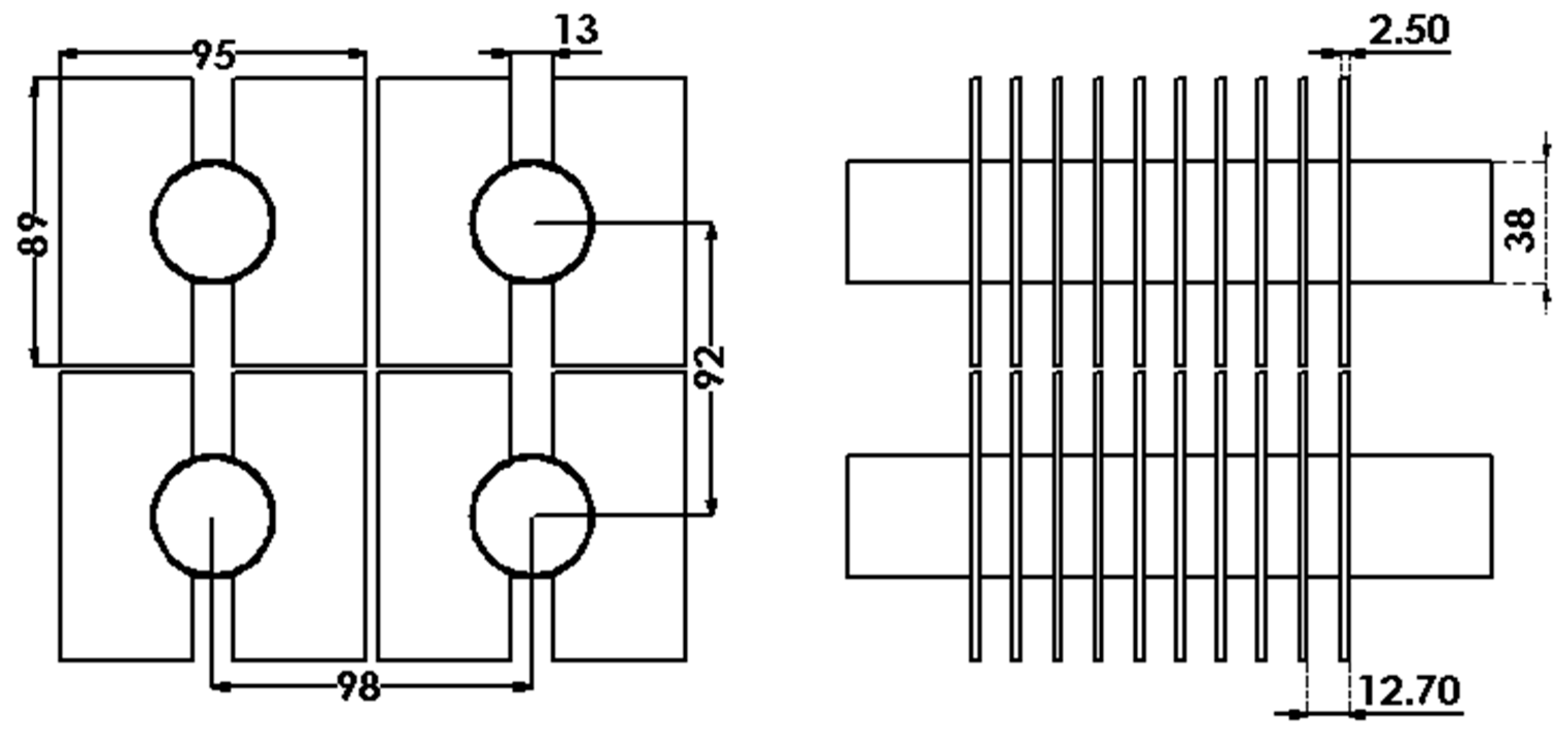
9] summarized detailed studies of rectangular, triangular, trapezoidal, concave parabolic, and convex parabolic profiles of extended fin surfaces. Despite that these designs may offer some considerable improvements, none of the aforementioned studies were associated with H-type finned tube banks that were popularly used in chemical processing and petroleum industry. Normally, the H-type finned tube bank houses a huge volume and weight that is not only costly, but also bulky as far as installation is concerned. In this regard, it is the objective of this study to elaborate some possible ways to reduce the surface area (or weight) of the H-type finned bank while maintaining the associated heat transfer performance. Both “partial-bypass”, trapezoidal, and wedge configurations have been proposed, and it will be shown subsequently that a maximum 14% improvement can be achieved. The reference case (denoted as Bank X) and a schematic of the typical H-type finned bank are given in
Figure 1.
2. Model Description and Numerical Method
2.1. Physical Model
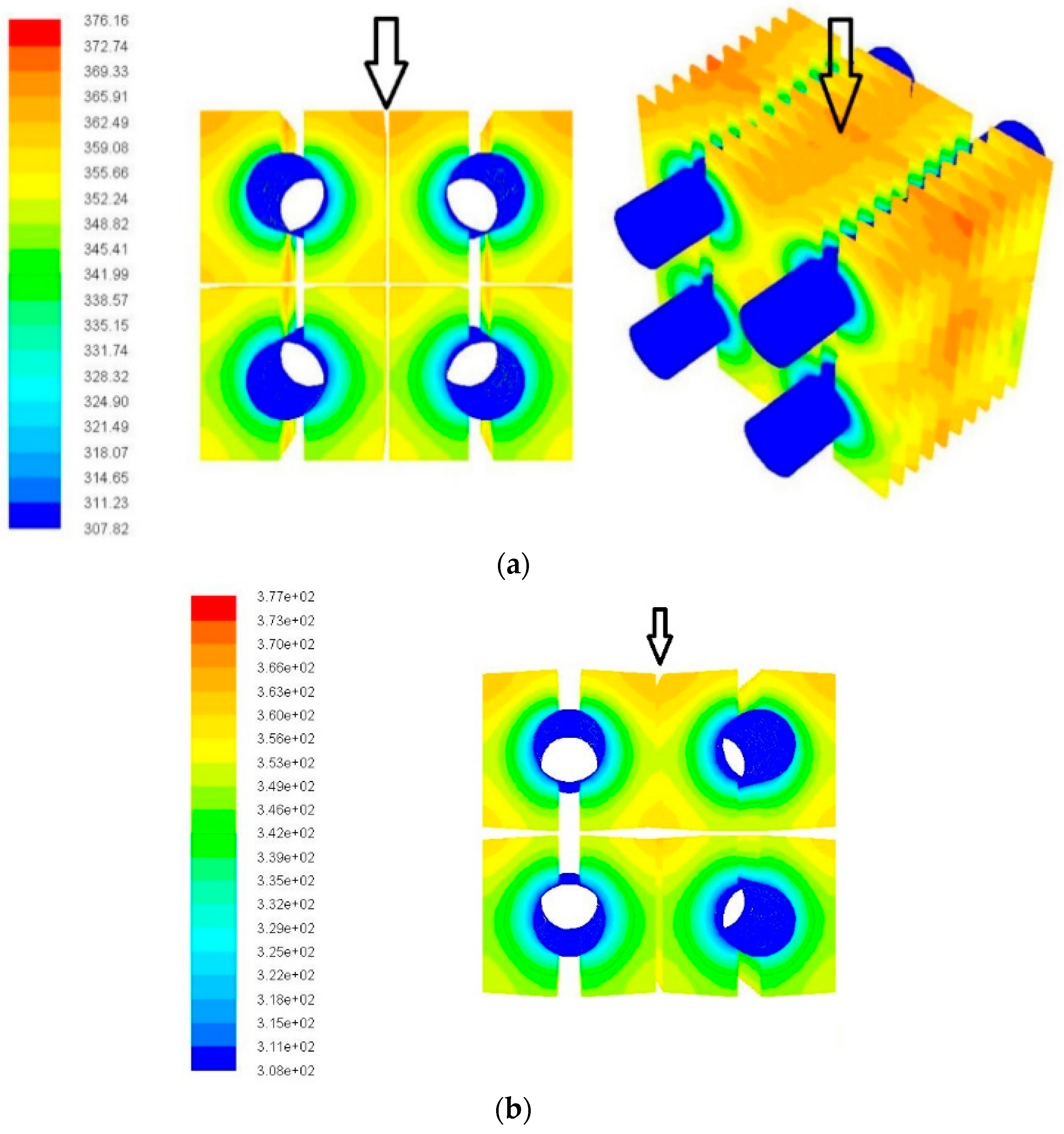
2.1.1. Design 1
The modifications in Design 1 are shown in
Figure 2a with a1 denoting the cutting length of the upper part from the air inlet, a2 the upper cut at the inner side (tube facing side), b the lower cut at the outer side, and c the upper cut in the bottom array of fins of the outer side. Different combinations of the simulations have been tabulated in
Table 1 (the original H-shaped tube bank without any cuts is termed as Bank X). The modifications are based on the idea of “partial bypass” by Wang et al. and Chen and Wang [
10,
11]. Since the heat transfer performance at the entrance of the heat sink (heat exchanger) often far exceeds that of the rear part of the heat sink, as a consequence, one can introduce some bypass airflow that is not in close contact with the surface at the entrance. Some part of the air then flows toward the rear part of the heat sink. Apparently, it will offer a larger temperature difference at the trailing part of the heat sink and a higher heat transfer rate accordingly. Through this manipulation, the heat transfer in the front part may be impaired, but the rear part may be significantly improved. There might exist a niche region by which the performance of the heat sink can be improved.
2.1.2. Design 2
The modification is schematically shown in
Figure 2b with characteristic dimensions p and q. The configuration contains a trapezoid fin shape alongside the flow direction. The fin surface takes the form as a trapezoid from the side view of the H-type heat exchanger while maintaining a uniform fin thickness. A couple of values for p and q are examined with the nomenclature for the banks as tabulated in
Table 1, and the results for heat transfer and material saving are discussed later in subsequent sections. For the reference case of Bank X, ‘p’ and ’q’ are equal to 89 mm.
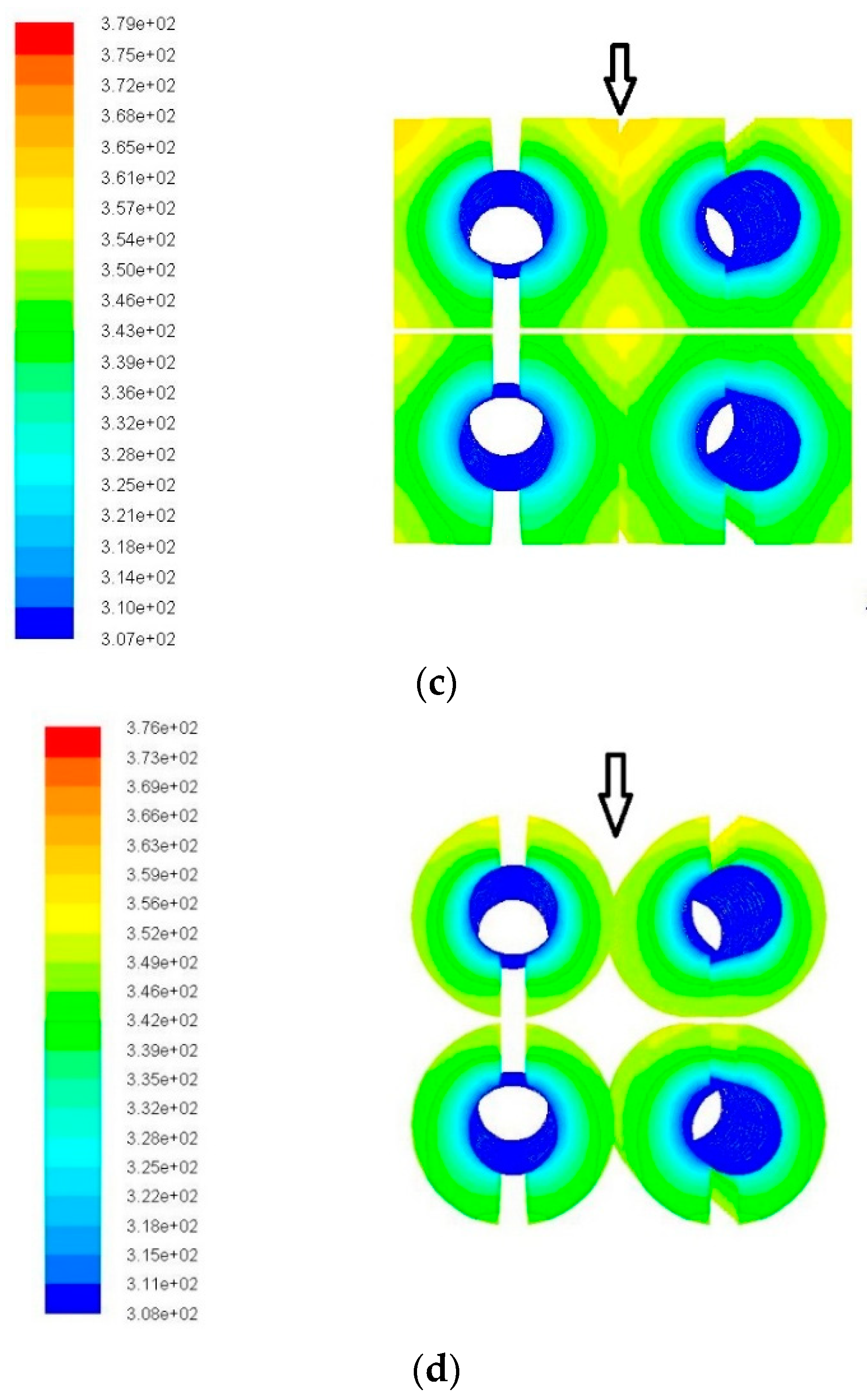
2.1.3. Design 3
In this design, the tube banks have a varying fin thickness while keeping the fin height and the fin width the same as the reference Bank X. The ratio of the fin tip to the fin base thickness is denoted as β. A typical diagram for Design 3 is shown in
Figure 2c. Tube banks with different values of β have been tabulated in
Table 1 with the tube bank having a rectangular cross-section (β = 1) becoming the reference Bank X. Note that the simulated cases for Design 3 with different β all contain the same volume (no weight change in fins).
2.1.4. Design 4
In this design, semi-circular fins are used instead of the generally-used rectangular fins for the H-type finned tube banks. A typical diagram for this tube bank is shown in
Figure 2d. The improvement in heat transfer performance and material saving for this design are discussed subsequently.
Table 1 also shows the value of the outer radius of the fins, and the rest of the parameters like fin thickness, gap between subsequent layers, number of tube rows, fin pitch, and base tube diameter are kept the same as that of the original Bank X.
2.2. Governing Equations and Turbulence Solver
The gas-solid flow in the test section is assumed three-dimensional, viscous, and steady incompressible turbulent flow. The realizable k-ε model with enhanced wall treatment is used to model the turbulent flow, and the corresponding equations are listed below:
The modeled transport equations for κ and ε in the realizable κ-ε model are:
where
,
,
,
In these equations, Gκ represents the generation of turbulence kinetic energy due to the mean velocity gradients. Gb is the generation of turbulence kinetic energy due to buoyancy, and YM represents the contribution of the fluctuating dilatation in compressible turbulence to the overall dissipation rate. C2 and C1ε are constants. σκ and σε are the turbulent Prandtl numbers for κ and ϵ, respectively. Sκ and Sε are user-defined source terms.
The standard k-ϵ model provides more accurate results for considerably high Reynolds number flows. ANSYS
R Fluent provides three types of k-ϵ models to be used for turbulence modeling, namely standard k-ϵ, the Re-Normalization Group (RNG) k-ϵ model, and the realizable k-ϵ model. Though generally, k-ѡ shear stress transport (SST) formulation are used for simulating low Reynolds number flows, many researchers use k-ϵ models with different wall treatments as this requires less computation time and resources. Further, it is also found that the RNG k-ϵ model and realizable k-ϵ model provide accurate results in numerical simulations (Zhao et al. [
7]). They found that the RNG k-ϵ model aligned nicely with their experimental data. The main drawback with k-ϵ model is that it is not very accurate in the near-wall computations. ANSYS
R Fluent has thus provided options for overcoming this shortcoming in these models by having an option of “Enhanced Wall Treatment” in the Near-Wall Treatment option with further selections of the pressure gradient effects and thermal effects in the near-wall region along with viscous heating. If the near-wall mesh is fine enough to address the laminar sublayer, then this method is quite similar to how the solver treats the turbulent modeling in the near-wall region in the k-ѡ SST model. Through this manipulation, contact sizings of the fins and the base tube region were added so that the mesh refinement is done carefully. The advantage of using this wall-enhanced treatment for the k-ϵ model is that the resultant model has lower computational requirements, which is considered to be advantageous in a number of practical engineering applications. A comparison of the results in terms of thermal resistance versus pumping power using the realizable k-ϵ model with enhanced wall treatment and the k-ѡ SST model is shown in
Figure 3. The results reveal an insignificant difference in the results obtained by using these two aforesaid models, and hence, the numerical solutions for all the designs considered in this study are obtained using the realizable k-ϵ model with enhanced wall treatment.
2.3. Boundary Conditions and Thermo-Physical Properties
At the upstream inlet, the fluid entering the computational domain is assumed to have uniform velocity and turbulent intensity with velocity components in the y- and z-directions being set to zero. Considering the symmetry of the test setup, a symmetric boundary condition is used along the flow direction so as to reduce the computational time for each test case. At the symmetry planes, the normal velocity component, the heat flux, and the normal first derivatives of other variables are also set to be zero. Periodic boundary conditions are used at the opposite ends, which are indeed perpendicular to the flow inlet direction (i.e., along the spanwise direction) to extend the flow domain.
The base tube is maintained at a constant temperature of Tw (or Tcold) = 308 K, and the wall thickness of the tube surface is ignored. The hot air temperature at the inlet is 376 K (Thot). The cell zone conditions for the tube are also maintained at a constant temperature. The difference in the results that are obtained, by using the constant temperature boundary condition and by the convective heat transfer boundary condition, for the tube wall surface are negligibly small.
The material used for both the fins and tube surface is carbon steel (1.5% C). The working fluid is air and all properties are evaluated at normal temperature and pressure. Since the thermo-physical properties of air like specific heat, thermal conductivity, dynamic viscosity, etc., change rather little with temperature range in the present simulations, thereby the influence of changes in the properties is neglected. All the banks are simulated with air inlet velocities ranging from 6–15 m/s. When the residual of each variable for gas phase is below 10−4, the numerical simulation is regarded as convergence.
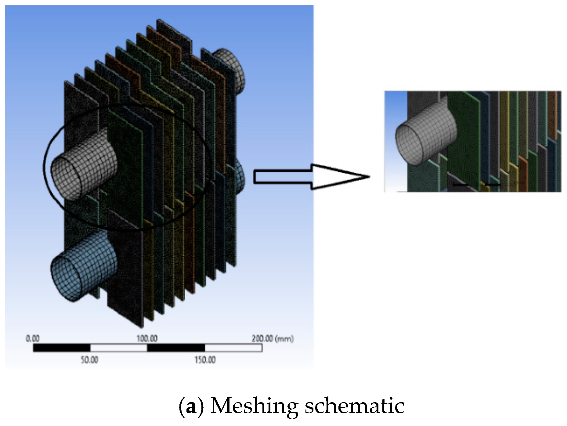
2.4. Meshing
The mesh is created in ANSYS Workbench using the inbuilt meshing feature in the Fluid Flow (Fluent) solver. The mesh for Bank X contains 3,458,898 elements with around 600,000 nodes. The advanced sizing functions are used over both proximity and curvature with high smoothing and slow transition. Eighty contact sizings of 2 mm each for the fin and base tube-contact regions are also used. The mesh is more structured over the fin surfaces and unstructured over the contact regions. The average orthogonal quality for the mesh elements is 0.89 with a standard deviation of less than 0.09. The typical mesh for the fin and tube surfaces for Bank X with a zoom in is shown in
Figure 4a. The meshing for all the other designs is carried out using similar settings, as well.
2.5. Grid Independence Test and Validation of the Computational Model
In order to validate the grid independency of the solutions, three-different mesh systems are investigated for the original H-type finned tube bank without any cuts (Bank X) using 2,670,583 (Grid 1), 3,458,898 (Grid 2), and 5,270,254 (Grid 3) cells. The comparison of the results for the three grids are shown in
Figure 4b in a graph in terms of thermal resistance vs. pumping power. Apart from the grid-independency test, the numerical results were compared with the experimental data from Chen et al. [
1]. The results for the heat transfer coefficient (h) and pressure drop (ΔP) for mesh with 3,458,898 elements are plotted against the experimental values in in
Figure 5a,b. The simulations are in line with the experimental results with 6% difference in predictive heat transfer coefficient (h) and the measurements, while being within 20% for the pressure drop (ΔP). The verification of the present simulation against the experimental results substantiates the applicability of the present simulations.
4. Conclusions
In this study, the heat transfer performance of H-type finned tube banks subject to different augmentations has been carried out. The modifications on the original H-type finned tube banks include the following: (1) Design 1 offers some triangular cuts at the edge of the original rectangular fin; (2) Design 2 modifies the original rectangular geometry into a trapezoid shape; (3) Design 3 renders the original rectangular cross-section fin thickness into a trapezoid cross-section; and (4) Design 4 changes the original rectangular shape into a circular shape. The foregoing designs make use of some possible surface/weight reduction and explore the possibility of the heat transfer augmentation. The designs are numerically investigated and compared with the traditional H-type fin surface with a rectangular cross-section, namely Bank X. Based on the foregoing discussion, the following conclusions are made as follows:
1. The fins with triangular cuts towards the edges (in Design 1) show very small improvements in the heat transfer performance and surface area reduction.
2. Bank K and Bank L (Design 2) adopting trapezoid fin shape can provide some weight saving and surface area reduction at a cost of slightly inferior heat transfer performance.
3. The fin surface with a wedge-shaped cross-section (Design 3) can offer up to 14% improvements in the overall heat transfer performance without any pumping power loss. The fin surface with a reverse wedge-shaped cross-section (thinner towards the base tube) imposes a negative influence on the overall thermal resistance.
4. The circular-shaped fins (Design 4) provide the maximum reduction in the weight as compared to the original reference case. With a 3–9% reduction in the surface area, the design still offers marginally higher heat transfer performance than the reference case. This is because it can provide a higher fin efficiency.


